HEMWAY M Series User manual
Smart steam generator
M Series Instructions
M090/M120/M180/M240/M360/M480
Hemway Smart Device
SHENZHEN HANMINGWEI SMART EQUIPMENT CO., LTD
Add:
Building 3B, 8 Cichang Road, Henggang, Longgang District, Shenzhen
Tell:0755-8467 9158 Fax:0755-2377 3276 htpp://www.hemway.com.cn
hemway@hemway.com.cn
Packing list
Product Installation Standards
Installation Guidance
六、 After sales service
Technical Parameters
External Product Structure
10
07-09
Operating Method
三、 Operation
11-12
After sales service
04-06
Product Introduction
15
15
Other fault analysis
13
14
四、 Maintenance
Maintenance
五、 Fault Analysis and Troubleshooting
Fault code analysis
STATEMENT
SHENZHEN HEMWAY SMART DEVICE CO.,LTD
All right reserved.
Without the express written permission of SHENZHEN HEMWAY SMART DEVICE
CO.,LTD, no unit or individual may act arbitrarily to reproduce, reproduce or trans-
late partor all of the contents of this instruction.
Shall not be used in any form or by any means (electronic, mechanical, photocopy-
ing,recording or otherwise) for the dissemination of commodities or for any
commercial orprofit-making purposes.
If there are any changes in the product structure and appearance, please refer to
thereal product.The product specifications and information mentioned in this
instruction arefor reference only and are subject to change without notice.Check
out our website at anytime:
http://www.hemway.com.cn
The product works under high temperature and high pressure environment.
Non-professional maintenance personnel are not allowed to disassemble the
product withoutpermission. Please refer to our warranty card for warranty.
Outside the warranty period, we also provide services. If you need to replace the
parts, we will charge a certain amount for the parts.
Unless otherwise agreement, this instruction is used only as a guidence and all
statements, information, etc. in this book do not constitute any form of warranty.
All interpretation rights belong to Hemway .
Product Introduction
INDEX

2、Drainage warning indicator
5、Working status switch
3、Water shortage indicator
4、Pressure setting button
1、Steam control switch
一、 INTRODUCTION External Product Structure
Host- Top side
Rate Evaporation
Size of Host
9kWM090 AC 380V 257*578*970(mm)
13.5L/H
1.5~5Kg/cm²
(Adjustable)
12kWM120 AC 380V 257*578*970(mm)
18L/H
18kWM180 AC 380V 400*700*1150(mm)
27L/H
24kWM240 AC 380V 400*700*1150
(mm)
36L/H
36kWM360 AC 380V 420*780*1210
(mm)
54L/H
48kWM480 AC 380V 420*780*1210
(mm)
72L/H
Technical Parameters
Model No. Rated Power Rated Voltage Working pressure
①
②
③
④
⑤
M series smart ironing steam generator is a garment ironing product independently
developed by our company and obtained a number of national patents. The product
has the functions of automatic water adding, frequency conversion heating, automatic
drainage , discharging and intelligent scale removal etc. At the same time, it has the
characteristics of adjustable pressure and fault code reminder. It is widely used for
many industrials.
The steam capacity of the product is sufficient to meet the requirements of small
ironing, medium ironing , big steam ironing, steam heating, preshrinking and other
industries . This product is suitable for all kinds of apparel factories, garment manufac-
turers, dry cleaners, hotels, clothing processing centers, home textile stores, curtain
stores, laundry etc. It can remove wrinkles and finalize the design of various fabrics,
achieve ideal ironing effect.
This product is a general-purpose steam generator that can be widely used as a
steam source in various industries that require steam. Such as: food, chemical, plastic,
textile, rubber, forest products, paper products and other industries.
Product Introduction
Pressure setting
O
F
F
R
e
s
t
O
N
Water tank low
level reminder
Drain Alarm
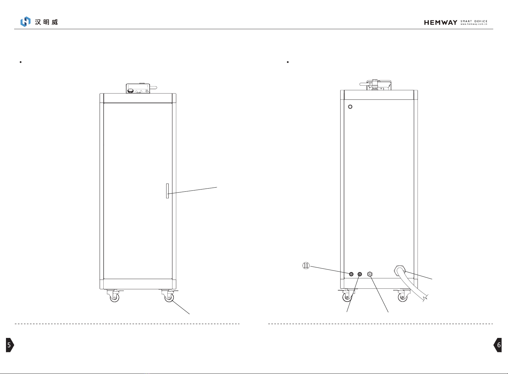
6、 Door handle 11、water inlet
7、Wheel 10、water tank outlet8、Power cable 9、 drainage outlet
Host-Front Side Host-Back Side
⑦
⑥
⑨⑩
⑧

7 8
二、 Installation Guidance
Power supply load standard
AC380V three-phase power supply line wire requirements
RVV5*4mm²
RVV5*4mm²
YC3*10mm²+2*6mm²
YC3*10mm²+2*6mm²
YC3*16mm²+2*10mm²
YC3*25mm²+2*10mm²
Model No
Model No
Distance between equipment
and main switch Wire specifications
Wire specification of
single machine
within 10 meters
M120
M090
M180
M240
M360
M480
Connect with 380V leakage
protection switch
380V
Leakage indicator
one push per month
T
Wiring & power supply instructions
Product Installation Standard
380V single equipment leakage protection
switch recommended
Equipment Model No Recommended leakage protection switch
M090 NXBLE-32 C20 3P+N
M120 NXBLE-32 C25 3P+N
M180 NXBLE-63 C40 3P+N
M240 NXBLE-63 C50 3P+N
M360 NXBLE-63 C63 3P+N
M480 NXBLE-125 C100 3P+N
Single equipment external transformer load specification
15KVA
30KVA
30KVA
35KVA
60KVA
110KVA
Transformer minimum power requirements
M120
M090
M180
M240
M360
M480
Notice
Leakage protection installation instructions (please select AC380V power supply line
according to the voltage shown on the equipment nameplate).
If the device is found damaged or parts are missing (including damage to the power cord,
etc.) when unpacking, please take a photo in time and contact our service center.
Do not install the device in damp and dusty places. Do not install or store the device
outdoors or in any direct sunlight, wind, rain, or freezing temperatures.
Please disconnect the power and turn off the steam control switch before installation.
If the power cord is damaged, stop using the device and contact an authorized service
center to prevent a security accident.
Do not connect the device to multi-hole sockets, power extension cords or adapters.
This device must be grounded to reduce the risk of electric shock and prevent static
electricity from affecting the device.
Failure to properly connect the equipment ground wire may result in a risk of electric
shock. Please connect under the guidance of a professional electrician or maintenance
personnel.
Our company will not bear any responsibility for all risk accidents caused by failure to
install standard wiring according to this manual.
Tighten the pipe connection to avoid falling off.
This equipment requires two or more people to move.
Note:Pls. break the power supply
line before connecting with leakage
protection switch.

910
Connect the water inlet pipe to the main water inlet pipe.
Connect the sewage pipe to the main sewage pipe.
Recommended installation method
Tip: Please use soften water
M series sewage pipe requirements
Equipment Quantity
1set
2set
3set
3/4” pipe
1” pipe
1.5” pipe
Pipe Diameter
Material(recommend)galvanized pipe
Packing List
plastic tiex2
Sewage outlet pipex1
Note: If you find any shortage or damage to the accessories, please
contact your local dealer in time.
Water Inlet pipex1
Hostx1
User manualx1 Warranty cardx1
drainage adaptorx1
Pipeline installation Note: After opening the outer package, please read the instruction manual
carefully and keep the relevant certificates properly
11 12
+
start working
During meal break
If you need to adjust the steam pressure, please
press the pressure setting area "-" or "+" on the
control panel.
During the noon break, turn the status switch to
the rest position, the corresponding indicator
lights, and the device enters the standby state.
Arrange for four minutes before get off work to
turn the status switch to the off-duty position,
and the equipment enters the drain state.
Before draining, make sure that the drain pipe is
firmly connected to the main drain pipe.
Note: The draining process takes about two
minutes. During this period, please do not
pull off the power supply.
Remarks: When the water shortage warning
light of the water tank flashes, it is in the
state of water shortage.
Remarks: The sewage reminder is to turn to
the sewage discharge state at the end of a
long time.
Turn the status switch to the working position,
the corresponding indicator on the control
panel lights up, and the system enters the work-
ing state.
Notice
Off-duty
Connect the main sewage pipe
三、 Operation Operation method
Please do not try to split any panel or disassemble the machine.
Do not use sharp tools to operate the control panel.
Do not repair or replace any parts of this machine by yourself. All repairs
must be performed by qualified service personnel and use authorized
original accessories.
Do not use other non-Hemway original parts instead of this machine parts.
Keep the bottom of the machine and the surrounding area free of combus-
tible substances, such as thread, paper, rags, chemicals, etc.
Do not open the door at will to avoid the entry of children or animals,
causing damage to the machine or personal injury.
Use the new hose or hose kit that comes with the machine. Using the old
hose may cause water leakage, resulting in property damage.
Do not put flammable or explosive substances inside the machine (such as
wax, wax remover, oil, paint, petroleum, degreaser, dry cleaning agent,
kerosene, gasoline, stain remover, turpentine, vegetable oil, cooking oil,
Acetone, ethanol, etc.), it is likely to cause fire or explosion.
Do not touch the pipe and pipe interface of the machine during operation
to prevent burns.
During the sewage draining process, please do not touch the draining water
to prevent burns.
In case of flooding, disconnect the power plug.
Do not use flammable gases and substances (benzene, gasoline, thinner,
petroleum, alcohol, etc.) near the machine.
If the drain pipe or inlet pipe freezes, please use it after melting.
Do not touch the power plug or electrical controls with wet hands.
Do not excessively bend all lines of the machine or place heavy objects on
them.
Please clean the dust and clothing fibers in the machine in time to avoid
short circuit, fire and fire.
Sewage pipe
Water tank low
level reminder
Pressure setting
Drain Alarm
O
ff
R
e
s
t
o
n
control panel
+
Water tank low
level reminder
Pressure setting
Drain Alarm
O
ff
R
e
s
t
o
n
control panel
+
Water tank low
level reminder
Pressure setting
Drain Alarm
O
ff
R
e
s
t
o
n
control panel
14
13
四、 MAINTENANCE
ITEM CONTENT FREQUENCY
draining after off work Daily
Weekly
Monthly
Monthly
Monthly
Monthly
Every Six
month
Drainage
Drainage pipe
Water inlet filter
Descaling
Deeply Descaling
Heat emission
Holes
Circuit
clean the filter head in case of not using soft water
and connected water supply pipe.
check the drainage pipe joints, and tighten it with
wrench if there is any loose;check the drainage pipe
for blocking, clean the pipe in time to avoid affect-
ing the drainage.
Descaling for using soft water .
Clean the residual scale in the boiler innerface, and
remove the water level detector and use sandpaper
to clean the scale on the surface;Clean the heater
and boiler innerface regularly (many scale accumu-
lates on the innerface of the heater used for a long
time, which will reduce energy efficiency and
increase power consumption. It is recommended to
replace it)
Check whether the short-cut protection circuit
function is normal, whether the short-cut protec-
tion circuit switch is loose, fire traces, use screw-
driver to tighten or replace it.
① Check the air outlet of the cooling fan regularly
for foreign matter and shielding (timely cleaning).
② Check regularly whether the cooling fan is
rotating normally (with or without wind power), and
maintain in time if any abnormality is found.
③ Clean the cooling fan filter regularly
2.Other Fault Analysis:
1.Fault Code Analyses:
Fault code
Fault
phenomenon
Fault
character
Fault point
Handling
method
F02
五、 FAULT ANALYSIS AND TROUBLESHOOTING
Check and
confirm methods
Abnormal time for adding water and replenishing water (when the water is
added for more than 6 minutes and none stop, or when the water is replenished
for more than 4 minutes and is not replenished)
water adding system error
Water source
Check if water
is blocked
Water pump Two position three
way solenoid valve
①Check if the pump is working
normally (there is slight
vibration and sound when
working normally)Water will
come out of the drainage pipe
within 5 seconds after starting
the machine.
②When there is no vibration,
check whether the pump power
supply end voltage is normal
(DC24V), normal means the
water pump is broken.
③No drain when vibration,
check whether the voltage at
the power supply end of the
pump is normal (DC24V),
otherwise the pump is broken.
①Check if the voltage at the
power supply end of two
position three-way solenoid
valves is normal (DC24V),
which is combined with crisp
sound under normal circum-
stances.No sound absorption
means that the water return
valve is broken.
②Under normal circumstanc-
es, suction but no water, it
means that the pipeline or
one-way valve blocked.
Replace water pump
Clean the blockage Replace water retrun valve or clean the
Fault Phenomenon Fault Character Fault Point Check And Confirm Methods Handling Method
Iron serious spraying
water
Abnormal water
level control
Water level sensor
scale
After drain, disassemble the equipment
to check if the water level probe is
scaling
Clean water level probe
Main control board
damaged
After drain, check if the voltage between
the water level probe and the hardware
plate where the probe is located is
AC12±1v;After the equipment is filled
with water, check if the voltage between
the water level probe and the hardware
plate where the probe is located is
AC0±1V.
① Replace main control board
② Check the water level line
and water level grounding port

15
六、 AFTER SERVICE
The screen does not
display and the power
indicator does not light
Pressure setting failure
The equipment cannot
enter the descaling
state
Abnormal power
supply
Pressure setting
system abnormal
Descaling abnorma Abnormal power
supply plug of the
cleaner
Electric leakage
protection switch
Check whether the electric leakage
protection input voltage is normal; if the
voltage is normal, check the output
voltage; if there is no voltage at the
output end, then the electric leakage
protection switch is damaged.
Replace electric leakage switch
Transformer
Pressure setting key
Main control board
Check if the transformer input voltage is
normal (AC220V), if the voltage is
normal, check if the transformer output
voltage is positive (AC24V);If the voltage
is abnormal, then the transformer is
broken.
Disconnect the power supply, open the
side cover of the device, press the
pressure setting key, and test the two
ends of the key with the multimeter.
Failure to connect means the key is
broken.
Disconnect the power supply, open the
side cover of the equipment, press the
pressure setting key, and test with
multimeter. If it is connected, the main
control board is broken.
Check if the power supply plug of the
cleaner is loose or not.
Replace transformer
Replace the keys
Replace main control board
Tighten the plug
If you have any quality problems or other problems after purchase Hemway products, please
contact the local distribut or hemway@hemway.com.cn for consultation.
To apply for a warranty must be in accordance with the below conditions:
① Please operate the machine strictly according to the manual when it is first started up and
used.
② Please use parts only from HEMWAY original
③ Please refer to the warranty card for other terms
This manual suits for next models
6
Table of contents
Other HEMWAY Iron manuals


