HEMWAY YUNBA H99X1 User manual

YUNBA H99X1 SMART IRONING STEAM GENERATOR
INSTRUCTIONS
SHENZHEN HANMINGWEI SMART EQUIPMENT CO., LTD
Add:
Building 3B, 8 Cichang Road, Henggang, Longgang District, Shenzhen
Tell:0755-8467 9158 Fax:0755-2377 3276
hemway@hemway.com.cn
STATEMENT
SHENZHEN HEMWAY SMART DEVICE CO.,LTD
All right reserved.
Without the express written permission of SHENZHEN HEMWAY SMART DEVICE
CO.,LTD, no unit or individual may act arbitrarily to reproduce, reproduce or trans-
late partor all of the contents of this instruction shall not be used in any form or by
any means (electronic, mechanical, photocopying,recording or otherwise) for the
dissemination of commodities or for any commercial or profit-making purposes.
If there are any changes in the product structure and appearance, please refer to
the real product.The product specifications and information mentioned in this
instruction arefor reference only and are subject to change without notice.Check
out our website at anytime:
http://www.hemway.com.cn
The product works under high temperature and high pressure environment.
Non-professional maintenance personnel are not allowed to disassemble the
product without permission. Please refer to our warranty card for warranty.
Outside the warranty period, we also provide services. If you need to replace the
parts, we will charge a certain amount for the parts.
Unless otherwise agreement, this instruction is used only as a guidence and all
statements, information, etc. in this book do not constitute any form of warranty.
INDEX
Product Installation Standards
Packing list
四 、
五 、
六 、
Technical Parameters
Product External Structure
06
07-10
01
01
05
12
11
13-14
15
02-04
Product Introduction
Product Introduction
Installation Guidance
Operating Guidance
Maintaince
Fault Analysis and Troubleshooting
After Service
三 、
Equipment Installation
2
1
Rated evaporation
water source pressure
Size of Host
H99X1
12kW
AC380V(Details pls. review the nameplate)
547*257*770mm
13.5L/H
1~3Kg/cm²
1.5~4.2Kg/cm² (Adjustable)
一、 PRODUCT INTRODUCTION
Product Introduction
Technical Parameters
YUNBA H99X1 Smart ironing steam generator
Name
Product Model
Heater Rated Power
Rated Voltage
Working Pressure
YUNBA H99X1 smart ironing steam generator is a garment ironing product
independently developed by our company and obtained a number of national
patents. The product has the functions of automatic water adding, frequency
conversion heating, automatic drainage,discharging and intelligent scale
removal. At the same time, it has the characteristics of adjustable pressure,
intelligent dormancy and fault code reminder. The steam capacity of the
product is sufficient to meet the requirements of small ironing,medium
ironing , big steam ironing and other industries .
This product is suitable for all kinds of clothing factories, clothing finishing
centers,home textile stores, curtain stores, laundry rooms, etc. It can remove
wrinkles and finalizethe design of various fabrics, achieve ideal ironing effect,
and meet the steam supply of other equipment.
8
7
6
2
3
4
5
5
1
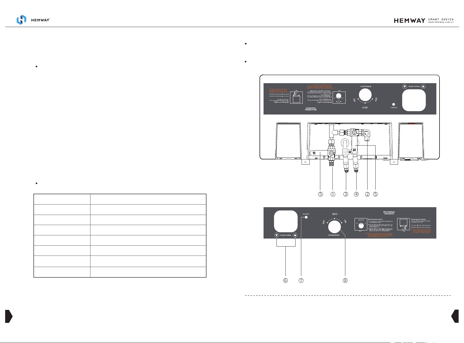
2、 Steam pipe interfaceⅡ
5、 Steam control switch
3、 Water return pipe interfaceⅠ
4、 Water return pipe interfaceⅡ
1、 Steam pipe interfaceⅠ
6、 Pressure setting button
7、 Drainage warning indicator 8、 Working Status Switch
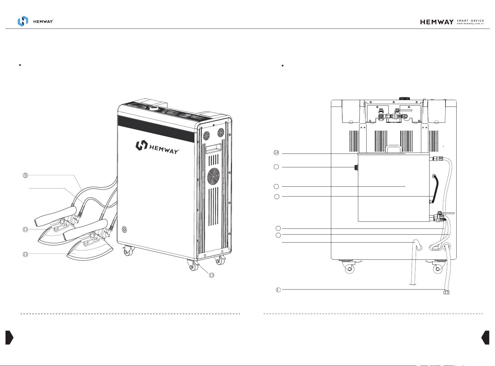
Product External Structure
Host--TOP
4
3
9
11
12
13
⑩
Host--FRONT
9、 Steam pipe 10、 Water return pipe 11、 IronⅠ12、 IronⅡ13、 Wheel brake
18
19
17
16
16、Water tank
17、Water level detector signal line 18、Condensate pipe 19、pump inlet pipe
15、Water source inlet
15
14、Water tank top cover
21、drainage pipe20、 power cable
14
⑳
1
Host--BACK
6
5
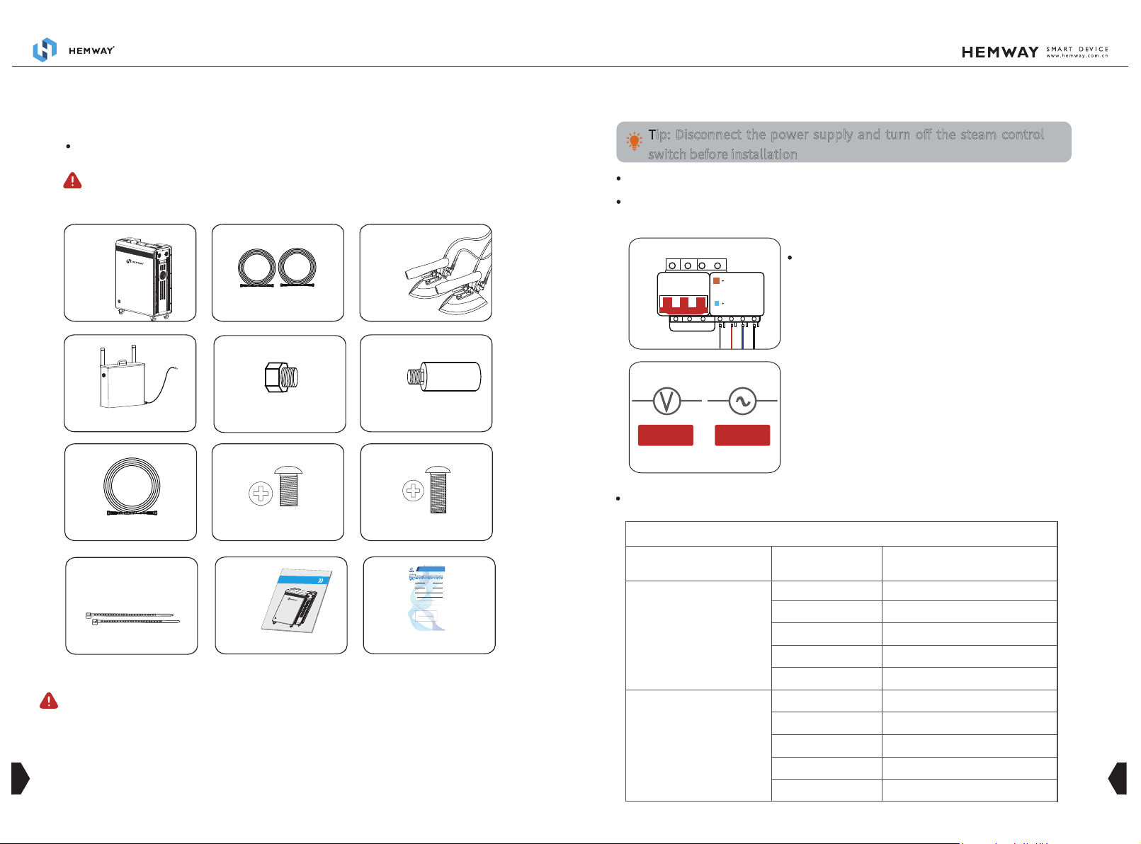
Water inlet pipex1
Water Tankx1
M4x8 Screwx4 M4x16 Screwx4
Packing List
Ribbon x 2
Drainage head x 1
Steam pipe x2
Water return pipe x2
Host x1Iron x 2
User's manual x 1 Warranty card x 1
Drainage adapter X1 (Optional)
when opening the outer packing, please read the instructions
carefully and keep the relevant certificates properly.
if there is a shortage or damage of parts, please contact the local
distributor .
NOTE
NOTE
二、 INSTALLATION GUIDANCE
380V 20A
Connect 380V Power short-Circuit
Protection
Note: Disconnect the power supply before connect
the Power short-Circuit Protection switch
380V/20A
漏电指示
每月按一次
T
When the rated voltage on rating label is
380V,the current of the supply line must no less
than 20A ,connect 380V Power short-Circuit
Protection and GROUND; use the corresponding
power supply line to avoid overload of the
circuit caused by the equipment being
energized.
Circuit Installation
Product Installation Standards
Power short-Circuit Protection Installation Instructions .
Tip: Disconnect the power supply and turn off the steam control
switch before installation
Power cable Load Standard
AC380V three-phase electric power supply line reference
one set
two sets
three sets
four sets
five sets
one set
two sets
three sets
four sets
five sets
within 10 meters
more then 10 meters
RVV5*4.0mm²
RVV5*6.0mm²
RVV5*10.0mm²
RVV5*16.0mm²
RVV5*16.0mm²
RVV5*2.5mm²
RVV5*6.0mm²
RVV5*10.0mm²
RVV5*10.0mm²
RVV5*16.0mm²
Device quantity
The Distance between
Power switch and devices power cable Specification
Dearcustomers:
Key part serial number
CustomerName PhoneNumber
DealerContactNumber
Dealer's stamp or Signature
Product Model PurchaseDate
MailingAddress
Warranty Card
Thankyou for your patronage of HEMWAY products! In order to protect your rights and
interests,please read the warranty terms and conditions on the back of this card carefully
and fill in the following information for safe keeping. Please show this card during
maintenance!
YUNBA H99X1 SMART IRONING STEAM GENERATOR
INSTRUCTIONS

78
Figure 2
Figure 1
Iron Installation
Equipment Installation
Water return pipe
Water return pipe joint
Steam pipe
Steam pipe joint
Steam pipeⅡ
Steam pipeⅠ
Water return pipeⅠ Water return pipeⅡ
Refers to figure 1,install the
steam pipe and water return pipe
of the iron on the corresponding
wiring port(Steam pipe joint and
Water return pipe joint ) and lock
them tightly.
Refers to figure 2,install the
steam pipe and water return pipe
of the iron on the corresponding
wiring port(Steam pipe joint and
Water return pipe joint ) and lock
them tightly.
(Disclaimer: Hemway will not be responsible for any consequences arising from the
failure to operate as required.)
Figure 4
Water tank installation
As shown in Figure 3, use 4 M 4 x 8
screws to fix the fixing bar on the
upper back of the water tank,
paying attention to the installation
direction of the fixing bar.
As shown in Figure 4, use 4 M 4 x 16
screws to fix the water tank on the
equipment, and tighten the screws
to prevent loosening.
water level detector
signal line
Figure 3
10
9
Float switch
water level detector
steam return inlet
water inlet
Figure 6
Figure 5
As shown in Figure 5, install the
floating ball on the float switch and
tighten it, and keep the floating ball
facing down vertically.
As shown in Figure 6, after fixing the
water tank, install the water pipes
as shown in the figure, paying
attention to the exhaust gas return
pipe, the water pump inlet pipe,
and the water tank water level
detector signal line.
After the initial installation or disassembly for maintenance, you must keep the
water! in the state for 10 minutes before turning on the machine to prevent the
pump from being damaged by dry pumping!
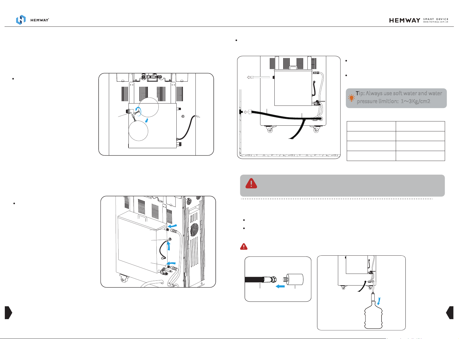
Device pipeline installation
Connect the water inlet connector
to the water inlet main pipe.
Connect the drainage pipe to the
drainage main pipe.
Recommend Installation Method
Drainage Pipeline Standard
Device Quantity
three sets
five sets
ten sets
3/4”
1”
1.5”
Pipe
Recommend Material: 304 stainless steel pipe,Op-
tional Material: galvanized pipe, PPR pipe
Tip: Always use soft water and water
pressure limition: 1~3Kg/cm2
Put the water inlet tube into the inlet bucket.
Optional Installation Methods (Not Recommend)
When the workshop does not install the water pipe
Tighten the connection between the drainage pipe and drainage head of the equipment and put
it into the drainage container.
(Disclaimer: Hemway will not be responsible for any consequences arising from the
failure to operate as required.)
Drainage
container
Sewage pipe Blowdown head
line
draniage main pipe
Drainage pipe
inlet pipe

12
11
下
班
O
F
F
(
排
污
)
Control Pane
下
班
O
F
F
(
排
污
)
Control Pane
To Start Working
To Take A Rest
三、 OPERATATION GUIDE
please carefully check whether all parts had been installed in
place,make sure every joint is tightly locked .
To adjust the steam pressure, please press
“ ” or “ ”in the pressure setting area of
the control panel.
Turn the status switch to the ON position, the
corresponding indicator on the control panel
light up,and the system enter the working
state.
During the lunch break, turn the status
switch to the REST position, the correspond-
ing indicator on the control panel light
up,and the system enter the standby state.
NOTE
When Off Work
Mode A:
Mode B:
Switch to the OFF position two minutes in
advance to off work, and thesystem enters
the drainage status. Please ensure that the
drainage pipe is connected in the following
way before draining:
Mode A: please ensure that the drainage pipe
is firmly connected to the main drainage
pipe;
Mode B: please ensure that the drainage pipe
is firmly connected to the drainage head and
put the drainage pipe with drainage head
into the drainage container.
the drainage process takes about two minutes,during which time do
not switch off the power.
(When draining, will cause heavy airflow roar voice, it is normal
phenomenon)
NOTE
Main drainage pipe
Connect the main
drainage pipe.
Main drainage
pipe
Connect the drainage
head and put into the
drainage container.
四、 MAINTENANCE
ITEM CONTENT FREQUENCY
draining after off work Daily
Monthly
Monthly
Monthly
Weekly
Every Six
month
Drainage
Drainage pipe
Deeply Descaling
Heat emission
Holes
Circuit
Water tank clean
check the drainage pipe joints, and tighten it with
wrench if there is any loose;check the drainage pipe
for blocking, clean the pipe in time to avoid affect-
ing the drainage.
Clean the residual scale in the boiler innerface, and
remove the water level detector and use sandpaper
to clean the scale on the surface;Clean the heater
and boiler innerface regularly (many scale accumu-
lates on the innerface of the heater used for a long
time, which will reduce energy efficiency and
increase power consumption. It is recommended to
replace it)
Check whether the short-cut protection circuit
function is normal, whether the short-cut protec-
tion circuit switch is loose, fire traces, use screw-
driver to tighten or replace it.
① Open the water tank cover to clean the water
tank.
② Please use soft water to reduce scale formation.
① Check the air outlet of the cooling fan regularly
for foreign matter and shielding (timely cleaning).
② Check regularly whether the cooling fan is
rotating normally (with or without wind power), and
maintain in time if any abnormality is found.
③ Clean the cooling fan filter regularly
14
13
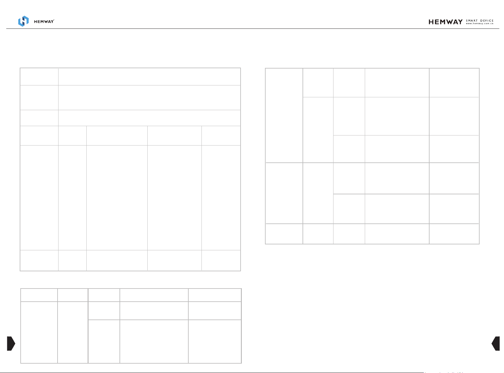
1.Fault Code Analyses:
Fault code
Fault
phenomenon
Fault
character
Fault point
Handling
method
F02
五、 FAULT ANALYSIS AND TROUBLESHOOTING
Check and
confirm methods
Abnormal time for adding water and replenishing water (when the water is
added for more than 6 minutes and none stop, or when the water is replenished
for more than 4 minutes and is not replenished)
water adding system error
Water source
Check if water
is blocked
Water pump Two position three
way solenoid valve
Water tank
(equipment with
water tank)
①Check if the pump is
working normally (there is
slight vibration and sound
when working normally)Wa-
ter will come out of the
drainage pipe within 5
seconds after starting the
machine.
②When there is no
vibration, check whether the
pump power supply end
voltage is normal (DC24V),
normal means the water
pump is broken.
③No drain when vibration,
check whether the voltage
at the power supply end of
the pump is normal (DC24V),
otherwise the pump is
broken.
①Check if the voltage at
the power supply end of
two position three-way
solenoid valves is normal
(DC24V), which is
combined with crisp
sound under normal
circumstances.No sound
absorption means that
the water return valve is
broken.
②Under normal circum-
stances, suction but no
water, it means that the
pipeline or one-way
valve blocked.
Check if there is
water in the
water inlet tank
check water
source
Replace water pump
Clean the
blockage
Replace water retrun valve or
clean the
2.Other Fault Analysis:
Fault Phenomenon Fault Character Fault Point Check And Confirm Methods Handling Method
Iron serious spraying
water
Abnormal water
level control
Water level sensor
scale
After drain, disassemble the equipment
to check if the water level probe is
scaling
Clean water level probe
Main control board
damaged
After drain, check if the voltage between
the water level probe and the hardware
plate where the probe is located is
AC12±1v;After the equipment is filled
with water, check if the voltage between
the water level probe and the hardware
plate where the probe is located is
AC0±1V.
① Replace main control board
② Check the water level line
and water level grounding port
六、 AFTER SERVICE
If you have any quality problems or other problems after purchase Hemway products, please
contact the local distribut or hemway@hemway.com.cn for consultation.
To apply for a warranty must be in accordance with the below conditions:
1. Please operate the machine strictly according to the manual when it is first started up and
used.
2. Please use parts only from HEMWAY original.
3. Please refer to the warranty card for other terms.
The screen does not
display and the power
indicator does not light
Pressure setting failure
The equipment cannot
enter the descaling
state
Abnormal power
supply
failed to connect
control board or
display board
failure
Pressure setting
system abnormal
Descaling abnorma Abnormal power
supply plug of the
cleaner
Electric leakage
protection switch
Check whether the electric leakage
protection input voltage is normal; if the
voltage is normal, check the output
voltage; if there is no voltage at the
output end, then the electric leakage
protection switch is damaged.
Replace electric leakage switch
LED Display
obnormal
connection wire
Pressure setting key
Main control board
Firstly check the power LED indicator on
the back of LED display, if it is on, If it is
on, use a multimeter to observe the
voltage between the second and third
pins of the main control board and the
ground wire. Normally, the DC voltage
should be about 2V, and the AC voltage It
should also be around 2V.
Inspection method: Use a multimeter to
measure the voltage between the two
ends of the wiring to the ground. If the
voltage at both ends is not the same to
the ground, it should be problem.
Disconnect the power supply, open the
side cover of the device, press the
pressure setting key, and test the two
ends of the key with the multimeter.
Failure to connect means the key is
broken.
Disconnect the power supply, open the
side cover of the equipment, press the
pressure setting key, and test with
multimeter. If it is connected, the main
control board is broken.
Check if the power supply plug of the
cleaner is loose or not.
If the power LED indicator is off
or the voltage is abnormal,
replace the display board
replace connection wire
Replace the keys
Replace main control board
Tighten the plug
Table of contents
Other HEMWAY Iron manuals


