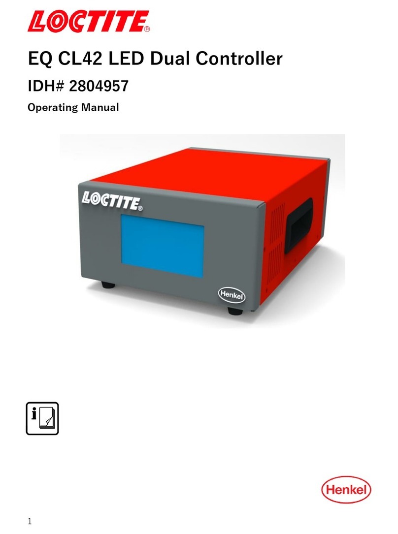
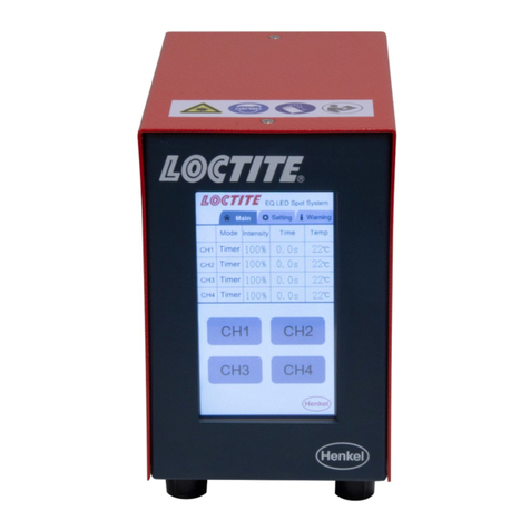
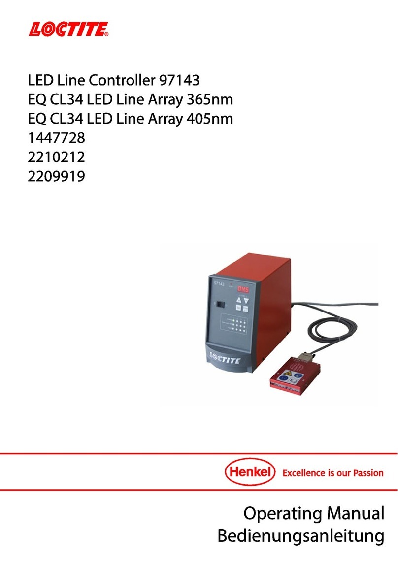
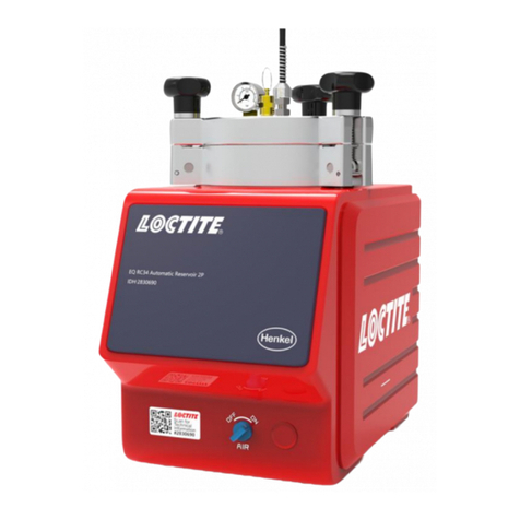
Henkel Loctite 97102 User manual

22121
97102
135550

2

3
Contents
1
Please observe the following...........................................................4
1.1
Emphasized Sections...................................................................................................4
1.2
Items Supplied .............................................................................................................4
1.3
For your Safety.............................................................................................................5
1.4
Field of Application (Intended Use)...............................................................................5
2
Description......................................................................................5
2.1
Theory of Operation .....................................................................................................5
2.2
Displays, Operating Elements and Connections...........................................................6
3
Technical Data................................................................................9
3.1
Energy Requirements...................................................................................................9
3.1.1
Electrics .......................................................................................................................9
3.1.2
Pneumatics..................................................................................................................9
3.2
Connections and Dimensions.......................................................................................9
3.3
Other Data ...................................................................................................................9
4
Installation.....................................................................................10
4.1
Environmental and Operating Conditions...................................................................10
4.2
Dimensions................................................................................................................10
4.3
Basic Settings of the Unit ...........................................................................................10
4.4
Connecting the Unit....................................................................................................10
5
Dispensing....................................................................................11
5.1
First Operation ...........................................................................................................11
5.1.1
Priming the Feed Line................................................................................................11
5.1.2
Adjusting the Dispensed Quantity...............................................................................12
5.1.2.1
Time Controlled Mode................................................................................................12
5.1.2.2
Continuous Mode.......................................................................................................13
5.2
Refilling the Product Reservoir...................................................................................14
5.3
Shutdown...................................................................................................................15
5.4
Returning to Operation...............................................................................................15
6
Maintenance and Service..............................................................15
7
Troubleshooting............................................................................ 17
8
Pin Assignment.............................................................................17
8.1
XS1: Start via Footswitch ...........................................................................................17
8.2
XS1: External Start.....................................................................................................18
8.3
XS1: Start via Promixity Switch ..................................................................................18
8.4
XS2: Digital Level Sensor Reservoir (Empty Signal)...................................................19
8.5
XS2: Automatic Reservoir 97106 / 97108...................................................................19
9
Declaration of Conformity..............................................................20

4
1
Please observe the following
Before installing the system: For safe and successful operation of the unit, read these
instructions completely. If instructions are not observed, the manufacturer will not accept
any liability.
Be sure to keep the manual close at hand for further reference.
The WEEE symbol on this equipment indicates that this product may not be treated as
household waste. By ensuring this product is disposed of correctly you will help prevent
potential negative consequences for the environment. For more information about where
you can drop off your waste equipment for recycling, please contact your local city office
or your waste disposal service.
1.1
Emphasized Sections
Danger!
Refers to safety regulations and requires safety measures that protect the equipment
operator or other persons from injury or danger to life.
Caution!
Emphasizes what must be done or avoided so that the unit or other property shall not be
damaged.
Note!
Gives recommendations for better handling of the unit during operation or adjustment as
well as for service activities.
The numbers printed in bold in the text refer to the corresponding position numbers in the
illustration on pages 6 –7.
–The dash emphasizes a list.
●The point emphasizes an instruction step.
Instruction steps in the illustrations are
indicated with arrows.
The shading of the arrows have the
following meaning:
Black arrow = 1st step
Grey arrow = 2nd step
White arrow = 3rd step
1.2
Items Supplied
1 Semi-Automatic Controller 97102, Order No. 135550
1 Power Cord
1 Pneumatic Tube 6 x 1, 2 m
1 Instruction Manual 97102
Note!
As a result of technical development, the illustrations and descriptions in this operating
manual may deviate in detail from the actual unit delivered.

5
1
Please observe the following
1.3
For your Safety
Please refer also to the relevant Technical Data Sheet for the adhesive to be processed.
Download from www.loctite.com or request the Technical Data Sheet and the Safety
Data Sheet from your Henkel Technical Service.
INSTRUCTIONS given in these data sheets must be followed scrupulously at all times!
While under warranty, the unit may be repaired by an authorized Henkel service
representative only.
Danger!
Improper handling of chemicals may result in potential health hazards!
Observe general safety regulations for the handling of chemicals!
Always wear goggles when working with compressed air!
Before starting operation, check the dispensing system for visible damage and make
sure that it is operated only when in perfect working order!
Any defects found must be reported immediately! Remedy any defects immediately!
Use only original substitute and spare parts. We cannot be held responsible for damage
or injury of any kind because of failure to observe the instructions in this Operating
Manual.
1.4
Field of Application (Intended Use)
The Semi-Automatic Controller 97102 controls the exact application of LOCTITE
Products from a product reservoir by means of a dispensing valve.
It can be combined with the following LOCTITE Units to from a dispensing system:
1 Product reservoir (product tank or cartridge reservoir emptying unit with or without low
level and empty sensor).
1 Pneumatic dispensing valve.
Depending on the combination of components, it is possible to dispense the following
products:
–Anaerobic curing adhesives
–UV light curing adhesives
–Humidity curing cyanacrylate adhesives
2
Description
2.1
Theory of Operation
The Semi-Automatic Controller 97102 controls the selected dispensing pressure in the
product reservoir and the pneumatic opening of the dispensing valve according to the
selected dispensing time.
The start signal for dispensing is provided by an external Footswitch.
Error messages are shown on the digital display and are accompanied by a beeping tone
(see Section 8).
When a product reservoir is connected, the pressurization or depressurization of the
automatic reservoir is automatically controlled when the control unit is switched on or off.
When an empty signal is received, the automatic reservoir 97106 / 97108 is
automatically depressurized.
The control unit indicates that the automatic reservoir was refilled. By acknowledging this
message with button the automatic reservoir is again pressurized.

6
2
Description
2.2
Displays, Operating Elements and Connections
1
Digital Display
Display of the dispensing time [s] for a dispensing sequence.
–During dispensing in time controlled mode, the dispensing time remaining is
indicated.
–During dispensing in continuous mode, the elapsed dispensing time is indicated.
Display of the dispensing pressure [bar] or [psi] set on the pressure regulator 8.
Display of error messages (see Chapter 7).
2
Buttons and
Buttons for changing the dispensing time for a dispensing sequence.
When button or is pressed, the display of the dispensing time [s] in the
digital display begins to blink. The dispensing time indicated is increased with
button and decreased with button .
The dispensing time is adjustable from 0.01 to 99.9 s.

7
2
Description
3
Button
Button for the storage of the new values set for the dispensing time [s] and the
dispensing pressure [bar] or [psi].
When the indication of the dispensing time [s] in the digital display blinks, the
indicated dispensing time is stored by pressing button and the display stops
blinking.
For an error message „ Press. 0.83 NOK“ with beeping, the error message is
acknowledged by pressing button . The value 0.83 [bar/psi] is only an
example for the indication of a dispensing pressure (see Chapter 7).
If the error message „ PRESS ENTER; >Tank Inactive< “ appears, the automatic
reservoir ( Tank) is pressurized by pressing ( PRESS) button ( ENTER) (see
Section 5.2.1).
4
Button
Button for filling the product line (see Section 5.1.1).
The LED lights as long as button is pressed.
When button is pressed in time-controlled mode, the dispensing time is not
changed.
The product is dispensed as long as button is pressed.
When button in pressed in continuous mode, the dispensing time is changed
(see Section 2.3)
5
Button
Button for switching the measuring units for the dispensing pressure in the digital
display.
After each pressing of button the indication of the selected dispensing
pressure in the digital display changes to the other measuring unit [bar] or [psi]
with the corresponding value.
6
Button
Button for switching from time controlled mode to continuous mode.
The lighting of the LED in button indicates continuous mode (see Section
5.2.2.2).
By pressing button the indication of the dispensing time in the digital display is
set to 0.00 s and blinks. During dispensing, the elapsed dispensing time is
indicated in the digital display beginning each time with 0.00 s. The last
dispensing time remains displayed until the next start.
–Switching back to time controlled mode without storage of the dispensing time
by renewed pressing of button . The LED in button extinguishes. In the
digital display, the dispensing time previously stored for the time controlled
mode reappears.
–Switching back to time controlled mode with storage of the dispensing time by
pressing button . The LED in button extinguishes. The indicated
dispensing time is stored and the display stops blinking.
7
Power Switch I/O (ON/OFF)
The control unit is switched on and off with the power switch.
When a product reservoir is connected, the following also applies:
Position I (ON) –The reservoir is automatically pressurized with the dispensing
pressure set on the precision pressure regulator.
Position O (OFF) –The reservoir is automatically depressurized.

8
2
Description
8
Precision Pressure Regulator
Precision regulator for adjusting the dispensing pressure.
By turning the regulator knob, the dispensing pressure is adjusted in the range
from 0.00 to 7.00 bar (0.00 to 100 psi).
If the error message „Press. 0.83 NOK“ appears with beeping, the dispensing
pressure was changed more than ± 10 %. The value 0.83 [bar/psi] is only an
example for the displayed dispensing pressure (see Chapter 7).
By pressing button ENTER the indicated dispensing pressure is stored as the new
comparison value for automatic pressure monitoring. The error message and
beeping is eliminated.
9
Control Air Connection (Dispensing Valve), dispensing valve open.
The single pneumatic hose to the dispensing valve is connected here (for
connections, see Section 8.2).
10
Control Air Connection (Dispensing Valve), dispensing valve closed.
The single pneumatic hose to the dispensing valve is connected here (for
connections, see Section 8.2). If a dispensing valve is used with single-acting
actuator, this plug must be closed with a blind plug.
11
a
P in - Main air connector
2 - 10 bar (30 PSI - 145 PSI) for air hose OD Ø 6 mm , ID Ø 4 mm
11
b
P out - Pneumatic Connection Reservoir
Regulated air pressure supply (0 - 7 bar, 0 –100 PSI) to the reservoir, for
air hose OD Ø 6 mm , ID Ø 4 mm.
12
Power Fuse
Caution!
Removing, jumpering or putting out of operation of the safety devices can result in
damage to the unit and is therefore prohibited!
13
Power Cord
14
Power Supply Socket
15
Footswitch (Accessory to be ordered separately!)
Signalling device for starting the dispensing sequence.
The dispensing time in time-controlled mode corresponds to the value on the
digital display and is independent of the length of time that the Footswitch is
depressed (see Section 2.3.1). In continuous mode, the product is dispensed as
long as the Footswitch is depressed (see Section 2.3.2).
16
Socket XS1: Start
The Footswitch 15 is connected here. A "Ready" signal is provided at Pin 3 and 4.
17
Socket XS2: Reservoir
The product reservoir is connected here.
+ 0.05
–0.10
+ 0.05
–0.10

9
3
Technical Data
3.1
Energy Requirements
3.1.1
Electrics
Power supply
90 –260 VAC; 47 –63 Hz
Power consumption
Approx. 40 W
Power protection
Glass tube, fine wire fuse, 2 AM
Internal control voltages
5 VDC; 12 VDC; 24 VDC
3.1.2
Pneumatics
Compressed air supply
min. 2 bar (29 psi); max. 12 bar (174 psi)
Quality
If the required quality is not
achieved, install a Loctite® 97120
filter regulator.
filtered 10 µm, oil-free, non-condensing
Order No. 88649
Regulation range of the pressure regulator
0.00 –7.00 bar (0.00 –100 psi)
Pressure indication
0.00 –7.00 bar (0.00 –100 psi)
3.2
Connections and Dimensions
Pneumatic hose, control air connection
O.D.
6 mm
Pneumatic hose, Dispensing Valve O.D.
4 mm
Pneumatic hose, Reservoir O.D.
6 mm
Dimensions
W x H x D: 145 x 230 x 260 mm
3.3
Other Data
Storage temperature
-10°C to +60°C (+14°F to +140°F),
dry/dust-free
Operating temperature
+10°C to +40°C (+50°F to +104°F)
Weight
~ 2.8 kg
Continuous sound pressure level
< 70 dB(A)
+0.05
-0.10
+0.05
-0.10
+0.05
-0.10

10
ve
4
Installation
4.1
Environmental and Operating Conditions
–Avoid kinking of the pressure hoses.
–Typically, the pressure hose should be no longer than 1 m.
–Carefully tighten all fittings.
–The equipment should be installed in a dry, dust-free place, no splash water!
4.2
Dimensions
4.3
Basic Settings of the Unit
4.4
Connecting the Unit

11
5
Dispensing
5.1
First Operation
5.1.1.
Priming the Feed Line
●Check that the product reservoir, the dispensing valve and the footswitch are
connected correctly according to their operating manuals.
●To avoid air bubbles during dispensing, the product line must be filled and then purged
of air.
●Position the dispensing valve as specified in its instruction manual to ensure bubble-
free filling of the product line.
Caution!
Place a container under the dispensing valve since the product will flow out.
●Switch the power switch 7 to the position I (ON).
●With the pressure regulator 8 set the
dispensing pressure to 0.50 bar
(approx. 7 psi).
●Press button until the product flows
free of bubbles from the dispensing
needle.
●For viscous products, increase the
pressure slowly in steps until the
product flows out.
Caution!
Hold the dispensing valve pointing downward to prevent uncontrolled squirting out of the
product.

12
5
Dispensing
5.1.2
Adjusting the Dispensed Quantity
5.1.2.1
Time Controlled Mode
This mode of operation is used for spot shaped wetting or drop dispensing.
●With buttons or set the dispensing
time to 0.50 s (factory setting). The
indication of the dispensing time in the
digital display begins blinking.
●With the pressure regulator 8 set the
dispensing pressure to 0.50 bar (approx.
7 psi). An error message „ Press. 0.83
NOK “ with beeping is possible. The
value 0.83 [bar/psi] is only an example
for the indicated dispensing pressure
(see Chapter 7).
●Press button to store the dispensing
pressure setting as the comparison
value for automatic pressure monitoring.
The error message with beeping is
eliminated.
●Press the Footswitch 15 to check the
dispensed quantity.
If the dispensed quantity is too small:
●Increase the dispensing pressure and store. Check the dispensed quantity again.
Repeat this sequence until the desired dispensed quantity is roughly achieved.
When the desired dispensed quantity is roughly achieved:
●Set the exact dispensed quantity by changing the dispensing time with button or .
●Press the Footswitch 15 to check the dispensed quantity.
Storing of the dispensed quantity setting for subsequent dispensings:
●Press button . The indication of the dispensing time in the digital display stops
blinking.
If the desired dispensed quantity is not achieved:
●With a larger (or smaller) dispensing needle, repeat the steps of Section 5.1.2.1.

13
5
Dispensing
5.1.2.2
Continuous Mode
This mode of operation is used for wettings of varying lengths or for the application of
beads.
●With the pressure regulator 8 set the
dispensing pressure to 0.50 bar (approx.
7 psi). An error message „ Press. 0.83
NOK “ with beeping is possible. The
value 0.83 [bar/psi] is only an example
for the indicated dispensing pressure
(see Chapter 7).
●Press button to store the dispensing
pressure setting as the comparison
value for automatic pressure monitoring.
The error message with beeping is
eliminated.
●Press button . The lighting of the LED
in button indicates continuous mode.
The indication of the dispensing time in
the digital display is set to 0.00 s and
blinks.
●Press the Footswitch 15 until the
dispensed quantity is roughly achieved.
If the dispensed quantity is too small:
●Increase the dispensing pressure and store. Check the dispensed quantity again.
Repeat this sequence until the desired dispensed quantity is roughly achieved.
–Switching back to time controlled mode without storage of the dispensing time by
renewed pressing of button . The LED in button extinguishes. In the digital
display, the dispensing time previously stored for the time controlled mode reappears.
–Switching back to time controlled mode with storage of the dispensing time by
pressing button . The LED in button extinguishes. The indicated dispensing time
is stored and the display stops blinking.
If the desired dispensed quantity is not achieved:
●With a larger (or smaller) dispensing needle, repeat the steps of Section 5.1.2.1.

14
5
Dispensing
5.2
Refilling the Product Reservoir
Error message „ --- Refill ---“
(see Chapter 7):
The error message display blinks.
●Prepare product for refilling.
Error message „ --- Empty ---“ with
beeping:
The error message display blinks. The
dispensing sequence is interrupted and no
further dispensing sequence can be
started.
●Press the button to stop the beeping.
The reservoir is automatically depressurized following the empty message.
●Refill the reservoir according to its instruction manual and reconnect.
Error message „ PRESS ENTER>Tank
Inactive< “(product reservoir (Tank) not
pressurized):
●Press button once (PRESS ENTER).
The reservoir is pressurized.
The error message „Press. 0.83 NOK“ (Press.= Dispensing pressure) blinks in the
digital display with beeping. The value 0.83[bar/psi] is only an example for the indication
of the dispensing pressure (see Chapter 7).
The error message „Press 0.83 NOK“ with beeping disappears by itself when the
dispensing pressure in the product reservoir does not deviate more than 10 % from the
stored comparison value of the automatic pressure control.
After the error message „ Press. 0.83 NOK “ with beeping has disappeared:
●Continue dispensing with the stored values for dispensing time and pressure.

15
5
Dispensing
5.3
Shutdown
●Switch the power switch 7 to the position O (OFF).
Shutdown for Longer Periods of Non-use
Caution!
For pauses in the work of longer than 14 days, place the system out of operation to
prevent curing of the product.
●Switch the power switch 7 to the position O (OFF).
●Put the product reservoir and dispensing valve out of operation according to their
instructions manuals.
5.4
Returning to Operation
●Switch the power switch 7 to the position I (ON).
●Continue dispensing with the stored values or readjust the dispensed quantity
according to Section 5.1.2.
Returning to Operation after Longer Periods of Non-use
●Check the installation according to Chapter 4.
●Return to operation according to Section 5.1.
6
Maintenance and Service
The unit requires no special care and maintenance.

16
7
Troubleshooting
Malfunction/Fault signal
Possible Cause
Corrective Action
The digital display does
not light.
–No power voltage present.
–Power switch 7 in position O (OFF).
–Power fuse 12 is defect.
–Power cord 13 is defect.
–Control unit is defect.
●Check the power voltage.
●Switch power switch 7 to position I
(ON).
●Check/replace fuse 12.
●Replace power cord 13.
●Henkel Service.
No change in the value on
the digital display
–No air pressure present.
–Product reservoir not switched on or
defect.
–Control unit is defect.
●Check pneumatic supply.
●Check product reservoir (see
operating manual for product
reservoir).
●Henkel Service
The error message (with
beeping) blinks in the
digital display:
Press.
=Dispensing pressure
0.83 [bar/psi]
=Example for the
indication of dispensing
pressure.
NOK
= Not O.K
–The unit was switched off and the
pressure regulator 8 in now
adjusting to the dispensing pressure
setting. The indicated dispensing
pressure is increased continuously.
–Pressure regulator 8 was
unintentionally changed by more
than ±10 %.
–Dispensing pressure was set to a
new value of more than ±10 %.
–Leak in the system
●Wait until the pressure regulator 8
has adjusted the dispensing
pressure.
●The error message and beeping are
eliminated when the indicated
dispensing pressure is within -10 %
of the stored comparison value.
●Adjust pressure regulator 8 until the
error message and beeping are
eliminated.
●Press button to store the
indicated dispensing pressure as the
new comparison value for the
automatic pressure monitoring. This
eliminates the error message and
beeping.
●Check system for leakage.
●Henkel Service.
The desired pressure is
not achieved.
–Supply pressure inadequate.
●Increase the supply pressure.
No product, too little or too
much product.
–Dispensing pressure not set
correctly.
–Pressure hose not properly
connected.
–Dispensing needle is clogged, too
small or too large.
–Dispensing valve not correctly
connected or defect.
–Product reservoir not switched on or
defect.
–Controller is defect.
●Adjust dispensing pressure setting.
●Connect air pressure hose correctly.
●Replace the dispensing needle.
●Check the dispensing valve (see
operating manual for dispensing
valve).
●Check product reservoir (see
operating manual for product
reservoir).
●Henkel Service.
LED in button or
does not light.
–LED defect.
–Button defect.
–Control unit is defect.
●Henkel Service.
●When the button I operational
(check by means of the digital
display), the unit can be used until
repaired by Henkel Service.
●Henkel Service.
●Henkel Service.

17
7
Troubleshooting
Malfunction/Fault signal
Possible Cause
Corrective Action
No start signal.
–Reservoir is empty.
The error message (with beeping)
blinks in the digital display:
–Automatic reservoir refilled but not
yet pressurized. The error message
blinks in the digital display:
Tank = Reservoir.
Inactive = Not pressurized.
–Plug on the socket XS1: Start 16 is
loose.
–Footswitch 15 defect.
–Control unit is defect.
●Refill reservoir (see Section 5.2).
The error message appears
previously in the digital display:
●Pressurize the automatic reservoir.
●Press button . The automatic
reservoir is pressurized.
●Switch the power switch 7 to the
position O (OFF).
●Tighten the screws of the plug.
●Switch the power switch 7 to the
position I (ON).
●Replace the Footswitch 15.
●Henkel Service.
8
Pin Assignment
Caution!
Never connect any external voltage on pin 9 of XS1 or XS2!
8.1
XS1: Start via Footswitch

18
8
Pin Assignment
8.2
XS1: External Start
8.3
XS1: Start via Promixity Switch

19
8
Pin Assignment
8.4
XS2: Digital Level Sensor Reservoir (Empty Signal)
8.5
XS2: Automatic Reservoir 97106 / 97108

20
9
Declaration of Conformity
This manual suits for next models
1
Table of contents
Languages:
Other Henkel Controllers manuals
Popular Controllers manuals by other brands
Inverto
Inverto Unicable II Installation & user guide
HydroStat
HydroStat 3200-Plus Installation instructions and operating manual

Pioneer
Pioneer DDJ-RB Service manual
Woodward
Woodward GCP-30 Series manual
Allen-Bradley
Allen-Bradley controllogix 1756-L61 Programming manual
TOPP
TOPP TOPP Installation and use instructions
