Henkel Loctite EQ CL25 HP User manual

44

2
Contents
English.............................................................................................................2 - 43
Deutsch........................................................................................................44 - 85
1
Please observe the following...........................................................................4
1.1
Emphasized sections...................................................................................................4
1.2
Items supplied..............................................................................................................5
1.3
Risk Group Measurement............................................................................................6
1.4
For your safety.............................................................................................................6
1.5
General Instructions.....................................................................................................7
1.6
Special Instructions......................................................................................................8
1.7
Features ......................................................................................................................8
1.8
Field of Application (Intended Use)..............................................................................9
2
Description...........................................................................................................10
2.1
Displays, Operating Elements and Connections ........................................................10
2.2
Theory of Operation...................................................................................................13
2.3
Operation Modes .......................................................................................................13
2.3.1
Time Controlled Mode................................................................................................13
2.3.2
Continuous Mode.......................................................................................................13
3
Technical Data...................................................................................................14
4
Installation............................................................................................................15
4.1
Environmental and Operating Conditions...................................................................15
4.2
Connections...............................................................................................................15
5
Operation..............................................................................................................17
5.1
First Start-up..............................................................................................................17
5.2
Shut down..................................................................................................................17
5.3
Start-up......................................................................................................................17
5.4
Indication of several Displays.....................................................................................17
5.4.1
LEDs..........................................................................................................................17
5.4.2
START/STOP Indication............................................................................................17
5.5
Setup the System ......................................................................................................18
5.5.1
Making Adjustments...................................................................................................18
5.5.2
Default Settings .........................................................................................................18
5.5.3
Restore Default Settings............................................................................................18
5.5.4
Set UV Intensity Level and Curing Time.....................................................................19
5.5.4.1
Setting Irradiation Intensity.........................................................................................19
5.5.4.2
Setting Curing Time and Continuous Mode................................................................19
5.5.5
Display of Head Temperature and Lifetime Information .............................................20
5.5.5.1
Display of Head Temperature ....................................................................................20
5.5.5.2
Display of Lifetime Information...................................................................................20
5.5.5.3
Resetting head lifetime and cumulative irradiation time values ..................................20
5.5.5.4
Operating Panel Lock ................................................................................................20
5.5.6
Setting of UV Intensity Measurement/Calibration.......................................................21

3
Contents
5.7
Operating the System.................................................................................................22
5.7.1
Time Controlled Mode................................................................................................22
5.7.1.1
Requirements for the READY signal to be on.............................................................22
5.7.1.2
Irradiation start...........................................................................................................22
5.7.2
Continuous Mode.......................................................................................................24
5.7.2.1
Requirements for the READY signal to be on.............................................................24
5.7.2.2
Irradiation start...........................................................................................................24
5.7.3
Emergency Stop (Stop during irradiation)...................................................................25
5.8
External Control .........................................................................................................26
5.8.1
RS232........................................................................................................................26
5.8.2
PC..............................................................................................................................28
5.8.2.1
Connect the Unit to the PC.........................................................................................28
5.8.2.2
General......................................................................................................................28
5.8.2.3
Setup of the software .................................................................................................29
5.8.2.4
Set 97079...................................................................................................................31
5.8.2.5
Using the “TYPE Setting” screen................................................................................32
5.8.2.6
Using the “UV.CHK” screen........................................................................................33
6
Maintenance and Service...............................................................................34
7
7...............................................................................................................................34
7.1
Warning Displays .......................................................................................................34
7.1.1
Temperature Warning ................................................................................................34
7.1.2
Time Warning.............................................................................................................35
7.2
Error Messages..........................................................................................................35
7.3
Malfunction/Fault signal..............................................................................................36
8
Annex.....................................................................................................................37
8.1
Spare Parts................................................................................................................37
8.2
Pin Assignment..........................................................................................................38
8.2.1
Control Connector 12 pin (2x) ....................................................................................38
8.2.1.1
Control Connector INPUT...........................................................................................40
8.2.1.2
Control Connector OUTPUT.......................................................................................41
8.2.2
RS232........................................................................................................................42
8.3
Declaration of Conformity...........................................................................................43
4
1
Please observe the following
Before installing the system: For safe and successful operation of the unit, read these
instructions completely. If instructions are not observed, the manufacturer will not accept
any liability.
Be sure to keep the manual close at hand for further reference.
The WEEE symbol on this equipment indicates that this product may not be treated as
household waste. By ensuring this product is disposed of correctly you will help prevent
potential negative consequences for the environment. For more information about where
you can drop off your waste equipment for recycling, please contact your local city office
or your household waste disposal service.
1.1
Emphasized sections
Warning!
Refers to safety regulations and requires safety measures that protect the equipment
operator or other persons from injury or danger to life.
Caution!
Emphasizes what must be done or avoided so that the unit or other property shall not be
damaged.
☞
Note!
Gives recommendations for better handling of the unit during operation or adjustment as
well as for service activities.
The numbers printed in bold in the text refer to the corresponding item numbers in the
illustration on pages 10-12.
●The point emphasizes an instruction step.
–The dash emphasises a list.
Numerations are indicated by bold letters and refer to the operating elements
at section 2.1.
Displayed terms and names of LED displays are indicated by italic letters.
All others by CAPITAL letters, except the term LED itself.
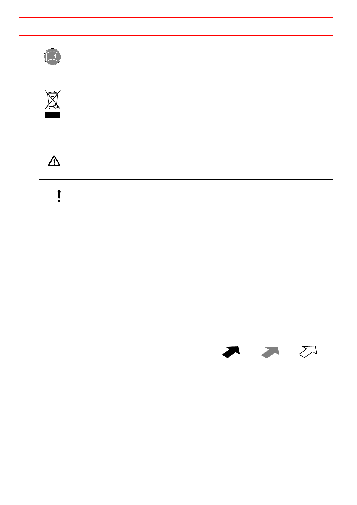
Instruction steps in the illustrations are
indicated with arrows.
Where several instruction steps are
indicated in an illustration, the colour
coding of the arrow has the following
meaning:
Black arrow = 1st step
Grey arrow = 2nd step
White arrow = 3rd step
5
1
Please observe the following
1.2
Items supplied
–1 pc. EQ CL25 HP LED Spot Cure Controller, former 97079, item no. 1786127,
including
–1 AC adapter 100-240 VAC
–Adapter Cord to connect Footswitch 97201
–Operating Manual
–Software on CD
–Connection cord to PC
The following parts have to be ordered separately:
Controller
EQ CL HP LED Spot Cure Controller, item no. 1786127
Lenses
3 mm
item no. 1305335
6 mm
item no. 1305333
10 mm
item no. 1305332
Connection Cords
Length 1.7 m
item no. 1305339
Length 3 m
item no. 1984961
Length 10 m
item no. 1305337
LED Heads
365 nm, short
item no. 1984957
365 nm, long
item no. 1984949
405 nm, long
item no. 2014788
Foot Switch
Item no. 88653
UV Meter
Item no. 1523721
☞
Note
As a result of technical development, the illustrations and descriptions in this operating
manual may deviate in detail from the actual unit delivered.
1.3
Risk Group Measurement
Measurement regarding the DIN EN 62471:2009-03; VDE 0837-471:2009-03 resulted in
the following risk groups:
–Lens, Diameter 3 mm RG1
–Lens, Diameter 6 mm RG3
–Lens, Diameter 10 mm RG3
–w/o Lens RG1

6
1
Please observe the following
1.4
For your safety
Please refer also to the relevant Technical Data Sheet for the adhesive to be processed.
Download from www.loctite-equipment.com or request the Technical Data Sheet and the
Safety Data Sheet (acc. to EC Directive 91/155/EC):
Henkel AG & Co. KGaA
+49 89 92 68 11 67 for the English language version of the data sheet;
089 92 68 11 22 for the German language version of the data sheet.
INSTRUCTIONS given in these data sheets must be followed scrupulously at all
times!
While under warranty, the unit may be repaired only by an authorized Henkel service
representative.
Warning!
Follow the manufacturer's instructions! Request a Safety Data Sheet for the Loctite®
product to be processed!
Controlling or calibrating this product by other than the procedures stipulated here could
cause exposure to dangerous LED radiation.
Damage to the power cord, the housing or the power adapter can result in contact with
live electrical parts.
Check the power cord and the unit before each use.
Never operate the system if the power supply unit / power cord is damaged! Replace a
damaged power supply unit / power cord with a new one.
Do not look directly at LED-UV light, or at LED-UV light reflected in a mirror or other reflective
surface. Doing so could cause eye damage.
Install the LED head in a way that humans are not exposed to LED-UV light.
Exposure could injure the skin or eyes.
Always turn off the key switch, before cleaning the LED head.
Cleaning the head while the switch is on could cause eye damage or injury to the skin.
Never disassemble this product. Disassembling this product could cause exposure to LED-
UV light, causing eye damage or injury to the skin.
If there is a risk of the LED-UV light being exposed to UV reflective light, place the product
inside a cover with proper reflectance and heat characteristics to block that reflected light.
When operating the controller, set up the system so that the path of the LED-UV light is not
at eye level.
It is strongly recommended to place a protective barrier around the product so that people
cannot approach it while it is operating.
Wear protective UV glasses and other protective clothing during operation.
Never operate this product in a manner not described in this manual. Doing so risks
exposure to LED-UV light.
Do not use any input power supply outside the specified range.
Do not use this product in a place where a large vibration or impact can be applied.
Never disassemble, repair, or modify this product in any way other than specified in this
User Manual.
We cannot be held responsible for damage or injury of any kind because of failure to
observe the instructions in this Operating Manual.
7
1
Please observe the following
1.5
General Instructions
–Do not connect this product to any power supply outside the power supply voltage and
frequency range indicated on the main unit and in this User’s Manual. Otherwise, this
product may be damaged.
–Do not place anything on the controller or block the air vents around this product to
prevent the occurrence of burns due to overheating.
–When handling the LED head, do not touch the lens or LED with bare hands. If a
foreign substance adheres to the lens or LED, it can cause the UV intensity to
decrease and the curing performance to degrade. If contaminations are applied to the
lens or LED, wipe it clean with alcohol and a lint-free cloth.
–Be careful not to drop or apply shock to the LED head. Doing so may damage this
product.
–Do not repeatedly bend the connection cables of the LED head, as this may result in
breakage. If any part of the LED head is broken, the whole LED head must be
replaced.
–Set the rubber feet of this product on a flat horizontal surface. Do not tilt this product or
put it on its side or upside down during use. The product may overheat and be
damaged.
–Do not use any other cable than the supplied connection cable to connect the LED
head to the controller.
–Ensure that the connection cable approx. 80 mm from the connector is kept free from
flexing stress and the joint between the connector and the cable is kept free from
tension. Otherwise, the cable may be broken.
–If the connection cable is longer than 2 m, or if the product is installed inside a larger
equipment, set up a display near the LED head so that the “LED radiation warning” can
be seen immediately. If you use OUTPUT terminals “+5V” (23) and “COM” (24) at the
rear of the controller, these will output a signal when the power is switched ON.
–Never connect any LED head, connection cable, AC adapter, or UV sensor to the main
unit, other than those designated by Henkel. Otherwise, any failure, loss, or damage
that may occur will not be covered under warranty.
–Never try to disassemble or modify the product, or to alter its internal settings. Any
failure or damage that occurs after disassembling or modifying the product will not be
covered under warranty.
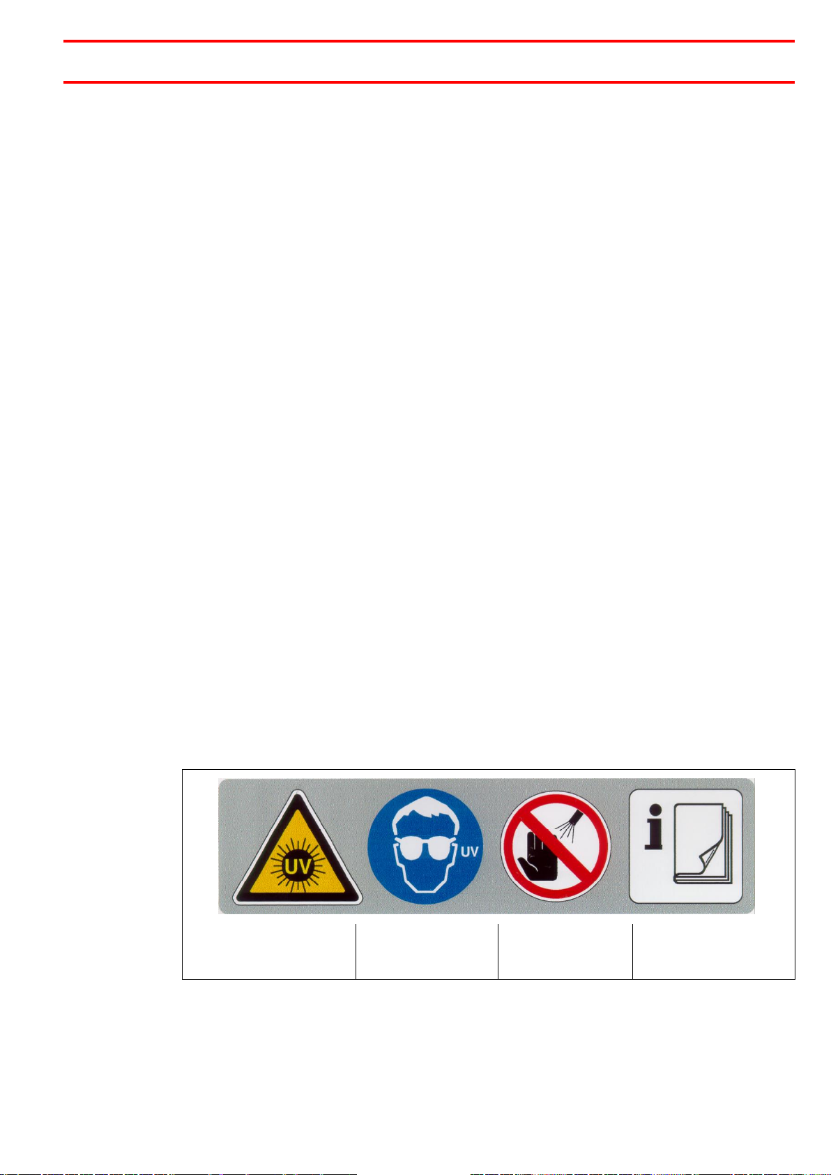
Explanation of the Label
UV radiation hazard
warning!
To protect your
eyes, wear UV
safety glasses!
Exposure could
injure the skin or
cause other injury!
Do not operate the
unit before reading
the Operating Manual!
For actions to be taken or avoided, see section 1.3 For Your Safety.

8
1
Please observe the following
When using more than 1 Unit
When using more than one controller, do
not bundle the supplied AC adapters
together. The AC adapters may overheat
and damage the products.
Ventilation
Cooling air is drawn through ventilation slots in the side panels of the controller. Do not
obstruct any of these air vents to make sure that ventilation air circulates throughout the
system. Obstruction of these openings will cause the unit to overheat.
Explosive Zones / Earthquake Zones
This unit is not specified for operation in explosive zones.
If operated in earthquake zones, the unit must be securely fastened.
1.6
Special Instructions
How to handle the Lens
Any contamination which has not been removed, such as fingerprints on the glass, will
bake to the surface and result in premature deterioration of performance.
☞
Note!
Fingerprints can be removed with a lint free wipe and pure alcohol. Before reassembling
the lens into the unit the alcohol must have evaporated completely!
Repair and Servicing
Refer all repairs to an authorized Henkel service center.
1.7
Features
LED Lamp Life
Based on an average power-on time of 8 hours per day and normal service conditions,
the lamp has an expected service life of 20,000 hours (Total irradiation time before the
UV intensity becomes 70% of the initial value).
Power irradiation
High-power irradiation 8,000 mW/cm2is standard when a 3 mm lens is used. It is
measured with a UV dosimeter type 98787, oder no. 1390323. Usually the unit is
purchased with a 6 mm lens.
UV curing without temperature increases
A single 365-nm LED UV light source is used, which does not include infrared radiation.
This eliminates the risk of heat damage to the workpiece.
Stable UV intensity
UV intensity is kept constant, even if the ambient or LED temperature changes.

9
1
Please observe the following
Use in a Clean Room
No cooling fan construction allows the use in a clean room. There is no need to deal with
exhaust. No ozon is generated.
Programmable UV irradiation with four individually controlled heads
Each LED head can be independently controlled by one controller. The heads can also
be controlled all together or in combination. Up to 7 different operation programs can be
stored for each channel (LED head), including one program for the constant intensity
irradiation and 7 programs composed of up to 10 steps each. Each channel can be
started separately. To setup such programs it is necessary to use the software and a PC.
The start of each program is possible only with an external start signal.
Program Examples
Operation Mode for each LED head with a start via button START/STOP or connected
footswitch:
Up to 7 individual programs can be set via PC, see section 5.8.2:
1.8
Field of Application (Intended Use)
The LED Spot Cure System is a specially developed high power radiation system for
curing Loctite UV adhesives and coatings with UVA radiation.
It can be used for manual workstations as well as for integration into automatic
production lines.

10
2
Description
2.1
Displays, operating elements and connections
1
Button START/STOP
In AUTO mode pressing this key starts a curing cycle. Pressing during a curing
cycle aborts it. Pressing in MANU mode starts the curing cycle and stopped with
pressing a second time.
2
Ready indicator
Indicates that irradiation is ready to start.
Stays on while irradiation is ready to start.
Stays off during irradiation.
3
Display red (3 digits)
4
Indicator for
Irradiation time in sec. (Con, 0.00-999 sec.)
LED head temperature (0-999 TEMP)
Cumulative LED life time (0-999 × 100 hrs)
Error codes (E00~E99)
UV intensity measurement (0.00-49.9 W/cm2)
5
Buttons LED Channel 1 - 4
To preselect the required channel.
6
LED indicator Channel 1 –Channel 4
Indicates CH selection and active CH during irradiation. Also indicates
temperature warnings and errors. The “CH” indicators flash during irradiation:
Green: During selection
Orange: Temperature warning or error
Red: During irradiation.
7
Key operated I/O switch
The controller unit of this product is put on or off via this key switch. Ensure that
the key is removed while this product is not in use.
8
UV sensor connection port
The optional UV sensor can be connected here.
9
Button UV Monitoring
Press button to start UV monitoring. The UV meter has to be connected.

11
2
Description
10
Button PLUS
To increase the setting values.
11
Button MINUS
To decrease the setting values.
12
Key lock indicator
Settings are locked (no changes can be made).
13
Button SET/ENTER
When pressed for more then 3 sec, switches to the setting mode.
When pressed in setting mode, saves the accepted settings in memory.
14
Button MODE/ESC
When pressed,
–switches between the different settings and modes.
–leaves the menu without storing the adjusted values.
15
Indicator for Intensity level in %
16
Display green (3 digits)
UV intensity modulation (0-100%)

12
2
Description
17
LED connection cable ports
for channels 1 - 4
18
Input terminal
(Pin Nos. 1 to 12), see section 8.2.1.1.
19
Output terminal
(Pin Nos. 13 to 24), see section 8.2.1.2.
20
Connection RS232C
Serial interface for connection of a programmable logical controller (PLC) or a PC
for programming.
Connect via null modem cable, but pins 7 and 8 must not be assigned. Observe
the serial interface protocol: 9600 baud/1stop bit/no parity/8 data bits.
21
Connector
for the supplied AC adapter (6 VDC)
22
Interlock line
(Pin Nos. 11 and 12)
UV radiation can be stopped by opening INPUT terminal “EMER” on the rear of
the controller. It is shorted with a shorting bar as a factory default. It can be
replaced by a connection of an emergency stop switch.

13
2
Description
2.2
Theory of Operation
The radiation cycle can be initiated with the button “START/STOP” in the front panel,
with a footswitch (sold separately), via PLC connection with an external start signal and
also via a PC connection.
Each channel can be started separately or all simultaneously.
The UV LED Curing System EQ CL25 High Power LED Spot Cure offers the possibility
of programming of each channel with 7 programmes each containing up to 10 steps only
via PC connection.
Within the programmes the value of intensity and time can be adjusted and changed for
each step.
This can be done only via a PC (RS232).
For the possibility to check the irradiation output of the LED head an optional UV power
meter is necessary. The power meter has to be ordered separately.
The intensity of each LED head can be calibrated and monitored. If the level is below of
an adjusted value an error message is available at the output interface. It is also
displayed on the controller.
2.3
Operation Modes
2.3.1
Time Controlled Mode
In this mode the unit can be started easily with setting curing time and intensity only
2.3.2
Continuous Mode
With this curing mode the irradiation can be started with the button START/STOP 1and
stoppes by pressing the button START/STOP 1again. The channels are started
simultaneously.

14
3
Technical Data
Power supply (external adapter)
100 to 240 V AC (10%), 50/60 Hz
Power consumption
60 VA
LED head
Max. output: 660 mW; Wavelength:365 ±5 nm;
LED risk group 3
Estimated LED life time
20,000 hours (LED head temp. at +60ºC, max)
Irradiation Intensity (mW/cm2)
(100% power) w/ 3 mm lens
up to 8000 mW/cm2
Connectable LED Heads
1-4
Connectable UV sensor
1
UV irradiation
One program for Simple Mode and up to 7 user-
definable programs (up to 10 steps each)
Display
Large colour-switching seven-segment LED
display
Storage temperature
-10°C to +60°C (+14°F to +140°F), dry/dust-free
Operating temperature Controller
Operating temperature LED Head
0°C to +35°C (+32°F to +95°F)
+5°C to +35°C (+41°F to +95°F)
Relative humidity
85% RH or lower (with no condensation)
Dimensions Controller (WxHxD)
80 mm x 127 mm x 140 mm (3.15“ x 5“ x 5.5“)
Dimensions LED Head w/ Cable
OD 12 mm x 50 mm, cable length 200 mm
(OD 0.472“ x 2“, cable length 7.9“)
Weight Controller
Weight LED Head w/ 1.7 m cable
1.3 kg
0.125 kg
Dimensions

15
4
Installation
4.1
Environmental and operating conditions
–Relative humidity: Not more than 85% RH, with no condensation.
–Make sure the rubber legs are set horizontally parallel.
–In order to avoid damage due to overheating, do not use if the area around the system
is blocked.
–The minimum allowable bending radius for the LED head cord is 33 mm. Using the cord
with a curve radius of less than 33 mm could cause damage to the cable.
–Do not place items on top of the main unit, or block its air vents.
–Excessive heat could damage the unit due to overheating.
–The equipment should be installed in a dry, dust-free place.
4.2
Connections
Connect the LED Head
Connect the AC Adapter
Caution!
When using more than one controller, do not bundle the supplied AC adapters together.
The AC adapters may overheat and damage the units.

16
4
Installation
Connect the external Signal Plug
Further information see Section 8.2.1
Connect the optional UV sensor

17
5
Operation
5.1
First Start-up
●Insert the key into the I/O switch 7.
●Set key operated I/O switch to I.
When the power is turned on a beep will
sound and the display will indicate startup
status. The display will then change to
operation mode (under the default
setting).
5.2
Shut down
●Set key operated I/O switch to 0.
5.3
Start-up
●Set key operated I/O switch to I.
The program finally adjusted is active again.
5.4
Indication of several Displays
5.4.1
LEDs
LED lights:
LED flashes:
READY LED
–Lit blue to indicate that
irradiation is ready to
start.
–Stays on while irradiation
is ready to start.
–Stays off during
irradiation.
Channel
LED
CH1- CH4
–Flashes green when
displaying the data of
chosen channel
–Flashes green to show a
connected LED head and
during selection
–Flashes red during
irradiation
–Orange flashing: Indicates
a temperature warning of
the LED head.
5.4.2
START/STOP Indication
The button START/STOP 1lit red and stays on during irradiation.
18
5
Operation
5.5
Setup the System
It will always be necessary to follow all steps. The sequence of steps should be followed.
Each programming step must be confirmed and saved by pushing the button
SET/ENTER 13. For setting up the system.
●For setting up the system press button SET/ENTER 13 for more then 2 sec.
5.5.1
Making Adjustments
Adjust the required value with buttons PLUS 10 and MINUS 11 and set the channels by
pressing the corresponding channel key.
If the adjustment is not confirmed or stored by pressing button SET/ENTER 13 the
display switches back to the setting before.
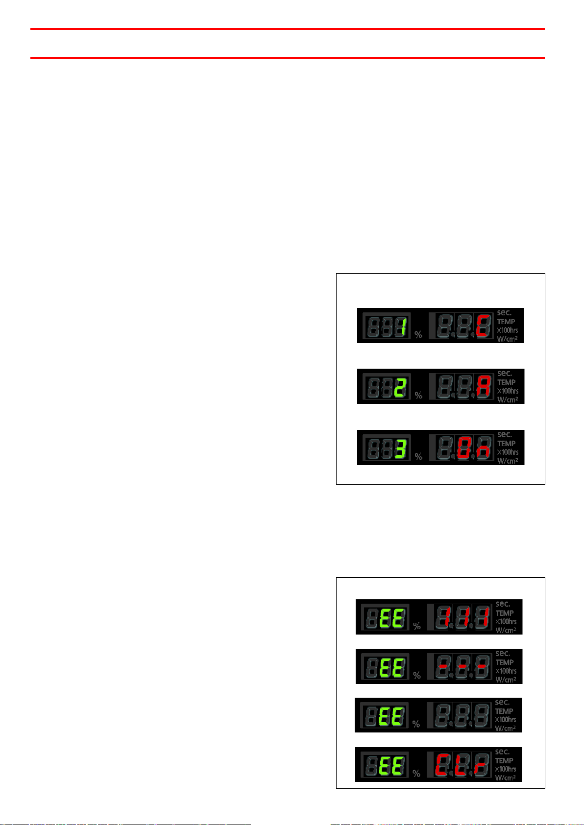
5.5.2
Default Settings
The default values are Celsius (°C) for temperature display, READY, and buzzer ON.
●To adjust the default settings press down
the button MODE/ESC 14 and
simultaneously switch power to I. Hold
the button till the startup display “1” and
“C” is shown.
●Use buttons PLUS 10 or MINUS 11 to
switch between °C (Celsius) and °F
(Fahrenheit).
●Press the button SET/ENTER 13. “2” and
“b” will be displayed.
●Use buttons PLUS 10 or MINUS 11 to
switch between A=READY and b=BUSY.
When using the unit in connection with a
higher ranking controller it is
recommended to set “A =READY”. At the
output terminals 14-17 a READY signal is
available, see section 8.2.1.
●Press the button SET/ENTER 13. “3” and “On” will be displayed.
●Use buttons PLUS 10 or MINUS 11 to switch between buzzer ON and OFF.
●Press the button SET/ENTER. The 1st display will be displayed.
●Hold down the button SET/ENTER to switch to operation mode and store the settings.
5.5.3
Restore Default Settings
All settings are restored to their initial default values.
●To adjust the default settings press down
the button MODE/ESC 14 and
simultaneously switch power to I. Hold
the button till the startup display “1” and
“C” is shown.
●While in default settings mode, press the
button MODE/ESC 14 till “EE III” will be
displayed.
●Hold down buttons PLUS 10 and MINUS
11 simultaneously till “EE ---“will be
displayed
●Hold down button SET/ENTER 13 as
long till “EE” is displayed.
When “EE CLr” appears all settings
have been restored to their original default
values (factory settings) and the controller
returns to operation mode.

19
5
Operation
5.5.4
Set UV Intensity Level and Curing Time
Set the irradiation intensity and curing time separately for each of CH1 to CH4.
☞
Note!
The displayed values apply to the selected and flashing channel.
●Select the channel to be set by pressing
buttons CH1 to CH4. The selected
channel is indicated by a green light
(flashing
or still).
It is not possible to select a curing channel
unless a LED head is connected to it.
5.5.4.1
Setting Irradiation Intensity
●Hold down the button SET/ENTER 13 to
select the CH to be set. (The selected
channel is indicated by a green light.)
Initially, only “%” (intensity) appears in
the green display.
●Use buttons PLUS 10 or MINUS 11 to
set the desired intensity value.
●Press button SET/ENTER 13 again to
confirm.
☞
Note!
While setting the irradiation intensity you can press the button START/STOP 1to start
UV irradiation. This makes it easy to make adjustments.
5.5.4.2
Setting Curing Time and Continuous Mode
●When you have finished setting the
intensity, the green display will
automatically display only “sec.”
●Use buttons PLUS 10 or MINUS 11 to
set the desired time value.
●Press the button SET/ENTER 13 again
to confirm.
●If you use button MINUS 11 to decrease
the setting below “0.0 sec” the display
will show “Con.” At this setting irradiation
will be continuous with no time limit.

20
5
Operation
5.5.5
Display of Head Temperature and Lifetime Information
5.5.5.1
Display of Head Temperature
●With the display showing irradiation
information, press the button
MODE/ESC 14.
●The head temperature is displayed.
●Press the Channel buttons to switch to
other channels.
5.5.5.2
Display of Lifetime Information
●With the display showing head
temperature, press the button
MODE/ESC 14.
The display shows the lifetime setting
(green) and cumulative irradiation time
(red).
●Press the Channel button to switch to
other channels.
●Press the button MODE/ESC 14 to return
to display of irradiation information.
5.5.5.3
Resetting head lifetime and cumulative irradiation time values
●With the display showing the lifetime
setting (green) and cumulative
irradiation time (red), hold down the
SET/ENTER 13 switch.
The lifetime setting (green) will be
displayed.
●Use buttons PLUS 10 or MINUS 11 to
change the lifetime setting.
●Press the SET/ENTER 13 switch.
●The cumulative irradiation time is
displayed (red).
●Hold down buttons PLUS 10 or
MINUS 11 simultaneously to reset the value to 0.
●Press the CH button to switch to other channels.●Press the button MODE/ESC 14 to
return to display of irradiation information.
●To cancel a change, press the button MOD/ESC 14. The display will return to showing
irradiation information, and the change will be lost from memory.
5.5.5.4
Operating Panel Lock
This is a way to safeguard the system
against unauthorised manipulation.
●In operation mode, hold down buttons
PLUS 10 or MINUS 11 simultaneously.
The settings will become locked and the
“LOCK” indicator will light up.
●To unlock the settings; hold down
buttons PLUS 10 or MINUS 11 again.
This manual suits for next models
1
Table of contents
Languages:
Other Henkel Controllers manuals


Popular Controllers manuals by other brands


Western Digital
Western Digital Ultrastar A2U24-S user guide

LEHMANN
LEHMANN Primary Controller operating instructions

YASKAWA
YASKAWA Lift Inverter L1000V Technical manual

ETS
ETS Train Controller ETS operating instructions

Continental Instruments
Continental Instruments CICP1100 datasheet

HP
HP Surestore Disk Array 12h - And FC60 installation guide