COATS H.I.T. 5000H2 Changer • v
Safety Instructions
Only properly trained personnel should
service tires on the H.I.T. 5000H2. Read all
safety and operating instructions thor-
oughly before using the tire changer.
ALWAYS
remove all wheel weights and the valve
core to deflate the tire before servicing.
ALWAYS
cover the electric motor and switch box
before hosing down the tire changer. Be sure water
does not enter the motor or switch box.
ALWAYS
disconnect the electric power and air sup-
ply before attempting any maintenance.
ALWAYS
keep all working surfaces clean and free of
tire lube buildup.
ALWAYS
be aware of what each person is and will do
before attempting any two-person operation.
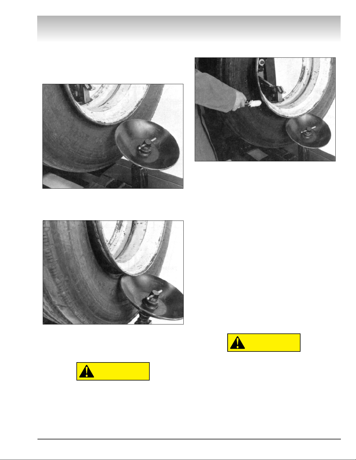
Bead Loosening
NEVER
place anything between the bead loosener
disc and the tire/wheel.
NEVER
place any part of your body between the
bead loosener disc and the tire/wheel, severe bodily
injury may result.
NEVER
allow the bead loosener to contact the
wheel, wheel damage may occur.
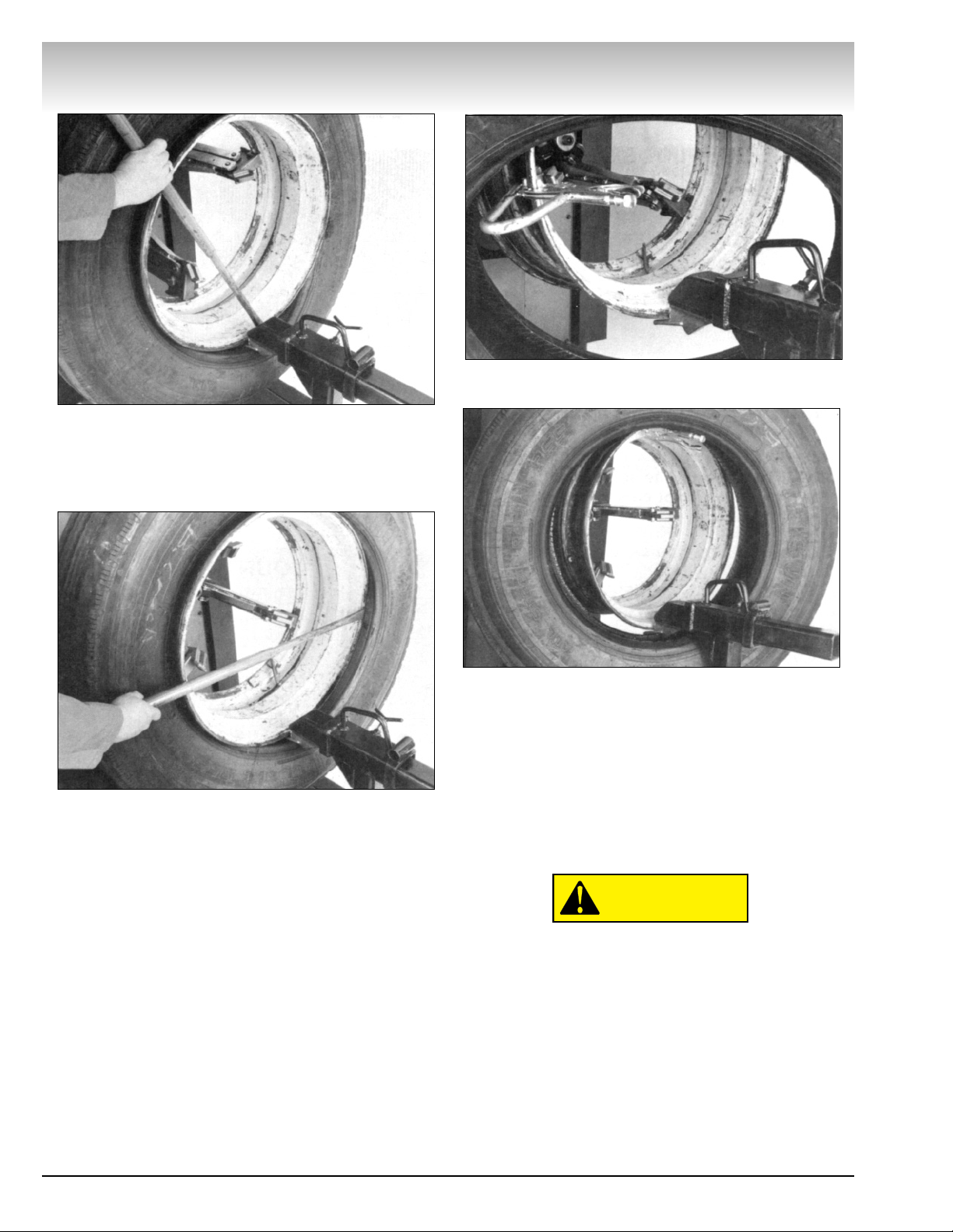
Demounting & Mounting
NEVER
stand on the working table while demount-
ing or mounting a tire.
ALWAYS
keep hands, feet, and other objects away
from moving parts while the machine in turned on.
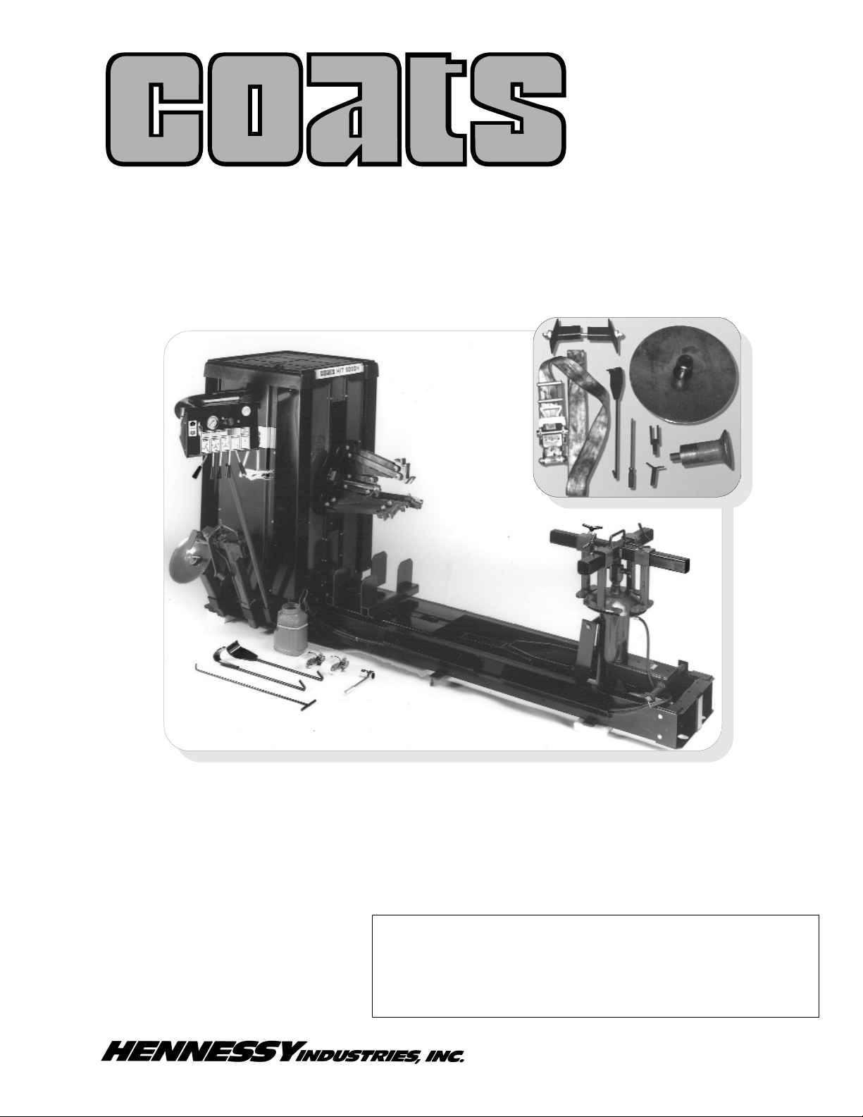
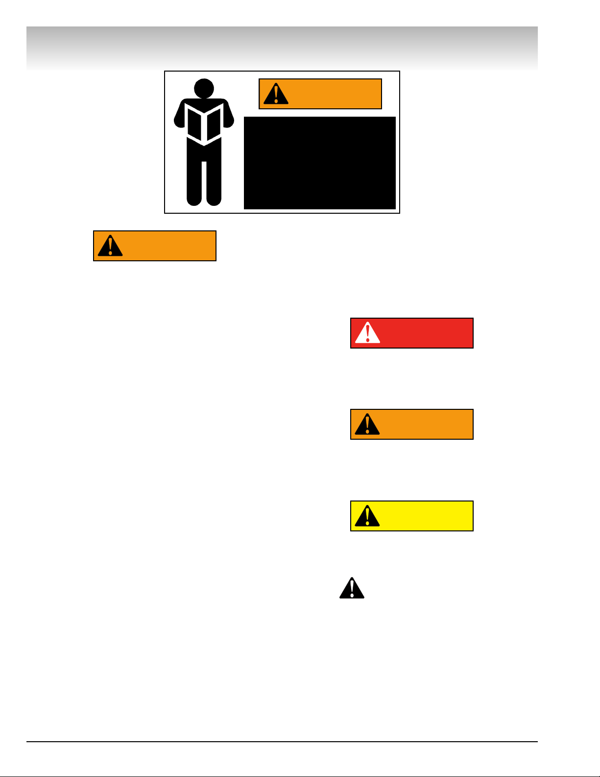
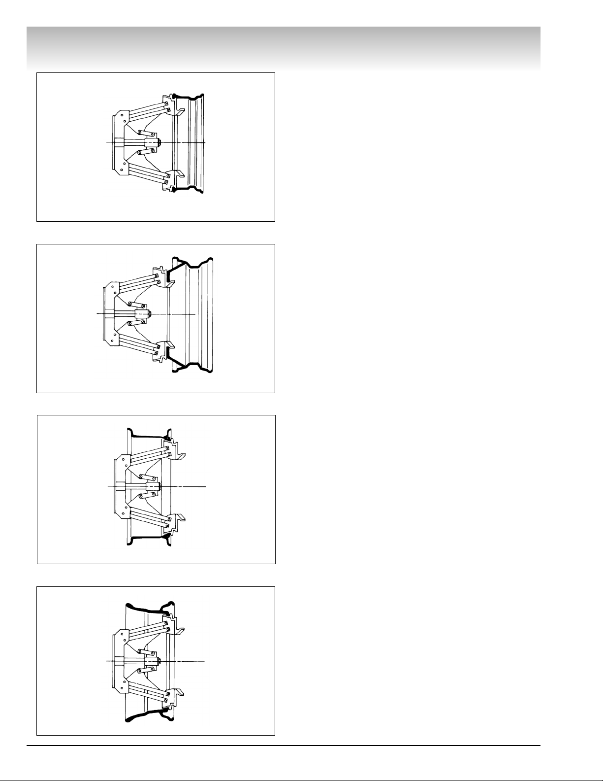
ALWAYS
place the narrow bead seat to the outside
when clamping. Failure to demount the tire from the
narrow bead seat side may cause damage to the tire
beads.
ALWAYS
apply an approved rubber lubricant to rim
flanges and both tire beads before demounting or
mounting and seating the beads.
NEVER
use
antifreeze, silicone, or petroleum base lubricants.
ALWAYS
clean and inspect the wheel.
NEVER
mount a tire on a damaged or rusty wheel.
Wheel damage or rust may cause tire or wheel failure
during inflation. Explosion from failure may result in
severe injury or death of the operator and bystanders.
ALWAYS be sure the bead opposite the tool is in the
drop center before rotating the tire when demounting
or mounting to avoid damage to the tire beads.
Inflation
ALWAYS follow all applicable Local, State, and
Federal Codes, Rules, and Regulations; such as the
Federal OSHA Standard Number 1910.177.
NEVER
seat beads or inflate a tire on the tire
changer. The H.I.T. 5000H2 is not designed as a safety
device or stand for bead seating or inflation.
ALWAYS
use an approved inflation chamber or infla-
tion cage.