Model BCF-24/65/110, BCM-110
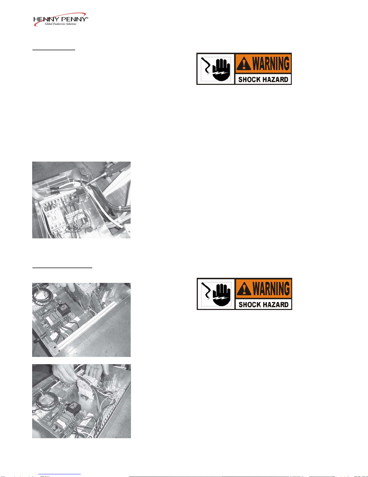
2-8. DOOR FRAME HEATER 1. Removetheelectrical powertothe unit.
Toavoid electrical shock orpropertydamage, move the
powerswitchto OFFanddisconnectmaincircuitbreaker,
orunplug cordatwall receptacle.
2. Remove the door to the unit by removing the screws in the
lower hinge of the door.
3. Remove the control box from the unit, following steps 2
through5in theControl BoardSection.
3. Remove the plastic tabs that secures the decorator covers
around the door opening, and remove the covers.
4. Peel theheater outof thegroove and disconnectthe wires
(insidecontrolbox) totheelement,and removetheelement
fromtheunit.
5. Install new heater in reverse order and press the plastic tabs
inplace tosecure thedecorator covers (tabsincluded withnew
heater).
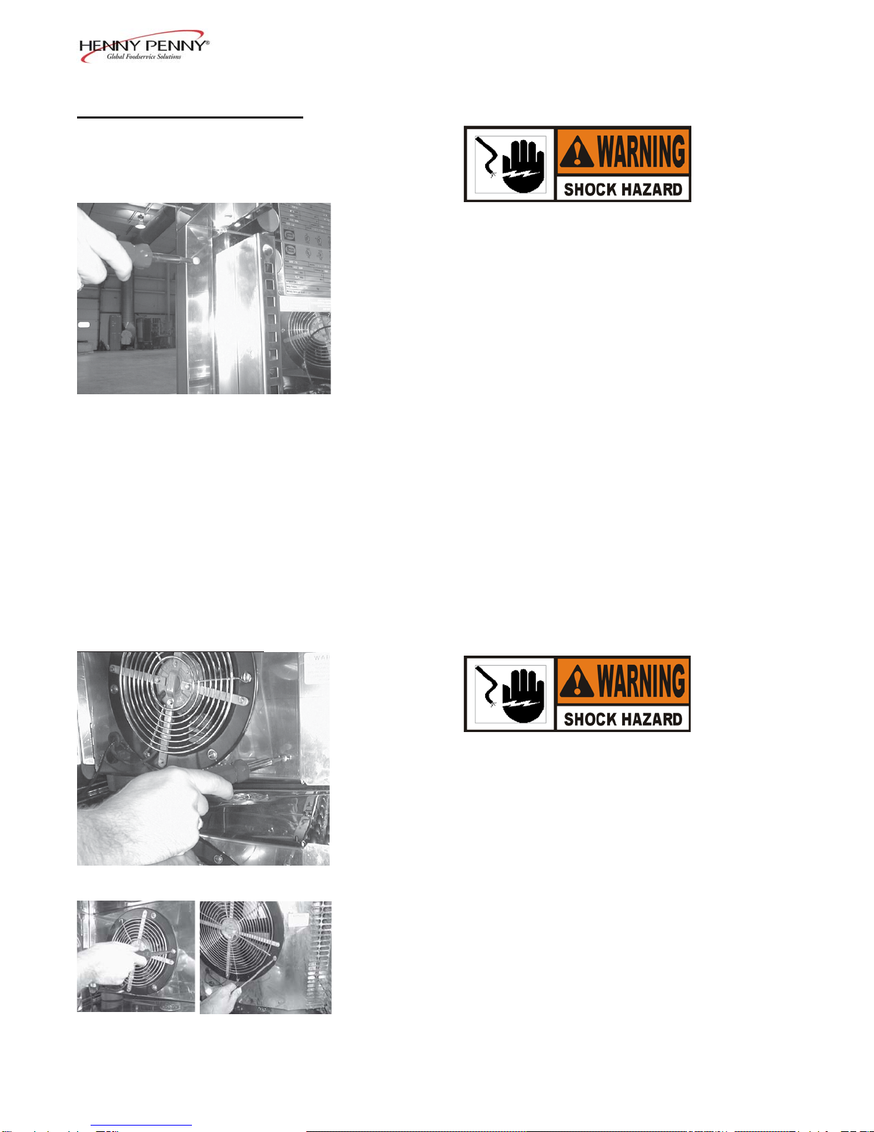
2-9. EVAPORATORFAN 1. Removethe electricalpowerto the unit.
Toavoid electrical shock orpropertydamage, move the
powerswitchto OFFanddisconnect maincircuitbreaker,
orunplug cordatwall receptacle.
2. Using aPhillipshead screwdriver,removethe twoscrews
securingthefan shroud,andpull outonthe shroud.
3. Using aPhillipshead screwdriver,removethe threescrews
securingthefan guard,andremove theguard.
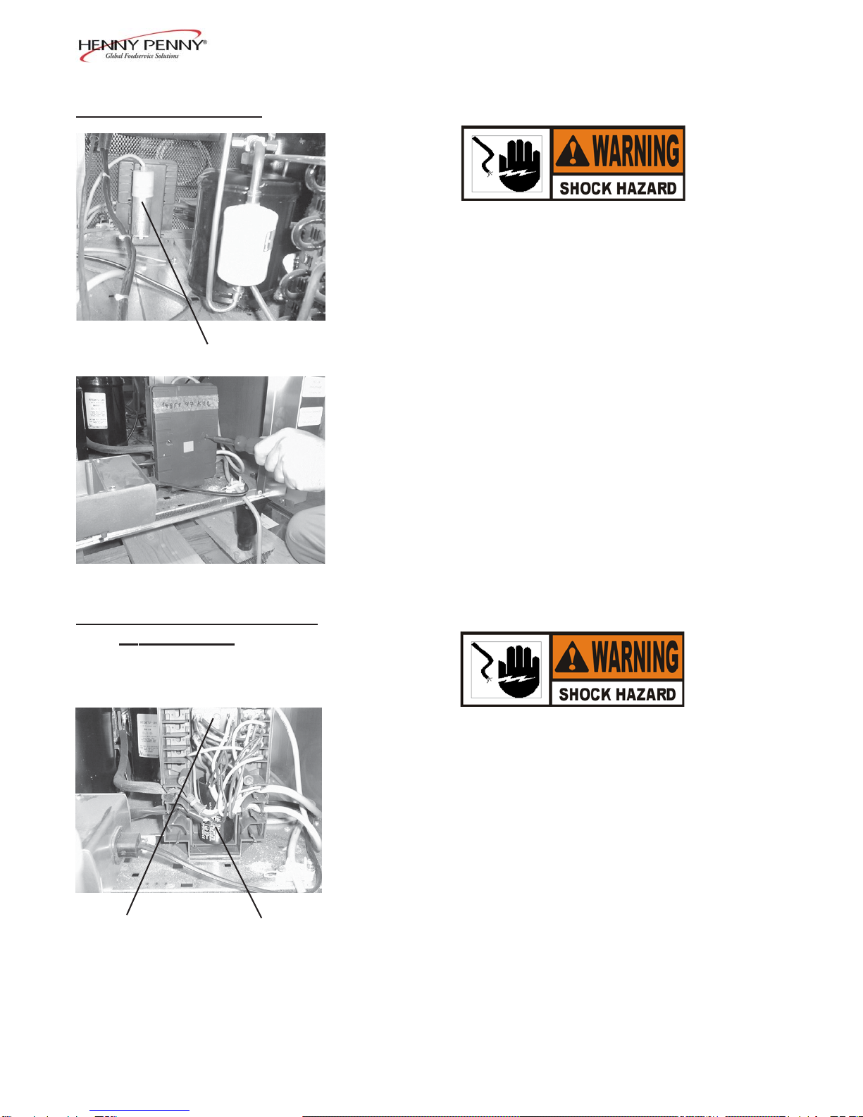
4. Remove thecontrolboxfrom theunit,followingsteps2
through5in theControl BoardSection.
5. Disconnect thewires(inside controlbox)to thefan.
6. Remove thethree screwssecuring thefan tothe evaporator
door,andpullthe fanfromtheunit.
7. Install newfanin reverseorder.
2-4 205