Hensel POrty L600 User manual

CHARGE
CHECK
23
24
25
2627
28 30
31
32
33
34
1 2 3 4
5
6
22
7
8
20
21
19 18 17 16 15 14 13 12 11 10 9
29

F1 F2 F3 F4
F5
F6
F7
Strobe Wizard Plus / freemask
P1 P2 P3 P4
P5
P6
P7
P9 P8
P1 P2 P3 P4
Profoto Air Remote Profoto Air Sync
P12
P10
P11
P13
P14

User Manual Porty L
4
HENSEL-VISIT GmbH & Co. KG
HENSEL-VISIT GmbH & Co. KG
Robert-Bunsen-Str. 3
D-97076 Würzburg-Lengfeld
GERMANY
Phone: +49 931 27881-0
Fax: +49 931 27881-50
E-mail: [email protected]
Internet: http://www.hensel.de
© HENSEL-VISIT GmbH & Co. KG, 2012
Distribution and reproduction of this documentation is not
permitted unless specifically authorized. In case of violation,
payment of damages will be due. All rights reserved, including
rights created by patent grant, or registration of a utility model
or design (ISO 16016).
Subject to technical changes. Errors and omissions excepted.
The listed data are standard values and not to be regarded as
guaranteed values in a legal sense. Values can deviate depen-
ding on component tolerance.
980009.00
Effective date: 02/2012

User Manual Porty L
5
HENSEL-VISIT GmbH & Co. KG
1 Preface
Dear photographer,
By purchasing the battery flash generator Porty L, you have
selected a high-quality and high performance product.
Below, we want to give you some details and hints on how to
use this unit. These will ensure successful and productive work
with it in the coming years.
Observing this necessary information entitles you to warranty
adjustments, prevents damages, and extends the operational
life of the unit.
Hensel-Visit took great care and observed all pertinent regula-
tions on order to manufacture a safe product of highest quality.
Stringent quality checks ensure our high quality standard even
in large-scale production.
Please add your part and handle the equipment with the neces-
sary care.
If you have any questions regarding the use of this equipment,
feel free to call us any time.
We wish you great success and „good light.”
HENSEL-VISIT GmbH & Co. KG

User Manual Porty L
6
HENSEL-VISIT GmbH & Co. KG
2 Content
1 Preface............................................................................4
2 Content...........................................................................5
3 Safety instructions ............................................................7
4 General ........................................................................10
Description...............................................................10
Scope of delivery ......................................................10
5 Technical data ...............................................................11
6 Summary of control elements .........................................13
7 Initial use.......................................................................14
Acclimatization .........................................................14
Set-up .....................................................................14
Battery operation ......................................................16
The charger Porty Lithium..........................................16
Battery charge status indicator...................................19
Mains operation with AC Porty mains drawer..............21
Flash head connection ..............................................22
8 Operation .....................................................................25
ON/OFF switch ........................................................25
Synchronization ........................................................25
Modeling light ..........................................................28
Power adjustment .....................................................29
Test flash ..................................................................31
Audio.......................................................................31
Flash readiness.........................................................31
Daily flash counter....................................................32

User Manual Porty L
7
HENSEL-VISIT GmbH & Co. KG
USB Interface ...........................................................32
9 Operation with Strobe Wizard Plus..................................33
Summary of control elements ....................................33
Setting transmitter.....................................................33
Setting receiver .........................................................34
Output adjustment....................................................34
Switching the modeling light......................................35
10 Operation with freemask................................................36
Settings for freemask method ....................................36
11 Operation with Profoto Air..............................................38
Basic functions..........................................................38
Summary of control elements ....................................39
Preparing transmitter ................................................39
Remote trigger..........................................................40
12 Maintenance .................................................................43
Regular maintenance................................................43
Replacing fuse ..........................................................43
Error messages.........................................................44
Warranty..................................................................45
Disposal...................................................................45
13 Customer service points .................................................46
Manufacturer’s service ..............................................46
Service points listed in the Internet .............................46
14 Accessories....................................................................47
15 Subject index .................................................................48
16 Declaration of Confirmity ...............................................49

User Manual Porty L
8
HENSEL-VISIT GmbH & Co. KG
3 Safety instructions
In addition to the general rules for handling electrical equip-
ment, the following safety precautions must be observed.
Read and observe the below listed information before initial
operation of the equipment.
Supply a copy of the safety precautions when selling, leasing, or
otherwise distributing this equipment.
ATTENTION!
Improper handling of the device, non-compliance with the safety
hints below, or tampering with the safety features can cause
property damage, bodily injury, electric shock, or even death.
The rechargeable flash generator Porty L is intended for pro-
fessional use inside the studio. Its purpose is the supply of
electrical energy for specified types of flash heads. The flash
generator is to be used only with the accessories described in
this manual and approved by Hensel-Visit.
The Strobe Wizard Plus transmitter, the freemask transmitter
and Profoto Air are used for triggering flashes and adjusting
the flash output of Hensel-Visit flash units with built-in receiver
via radio signal.
The appliance may not be used for any other purpose than
described above, especially not for other electrical applications.
Set-up and initial operation
• Do not use flash units in explosive environments.
• Before connecting the AC mains drawer to the power sup-
ply, make sure that the mains voltage corresponds to the
specifications listed on the unit’s specification plate.
• The Porty with AC mains drawer must only be connected to
grounded power supply systems.
• Check the protective conductor function of the power supply
before initial use.
Normal Use
Abnormal use

User Manual Porty L
9
HENSEL-VISIT GmbH & Co. KG
• Only use plugs/connectors with flawless contacts. Burned or
corroded plug contacts can cause fires. Defective plugs can
cause substantial damage to the plug socket.
• Do not connect accessories from other manufacturers, even
when these look similar or alike.
• To prevent damages and tripping hazards, avoid laying
cables on the floor. If this is not possible, make sure that
the cables cannot be damaged by vehicles, ladders, etc.
• Damaged cables and housings need to be replaced imme-
diately by an authorized service department.
• Keep the minimum distance around the equipment unobst-
ructed to ensure proper ventilation.
• Do not place any objects on top of the equipment (coffee
cups, vases, containers filled with water, etc.).
• Choose safe locations for set-up and make sure that the
equipment cannot fall into pools or bodies of water.
• Keep proper distance from flammable materials like deco-
rative fabrics or paper to prevent the risk of fire.
• Secure the equipment with a back-up support when atta-
ching it to ceilings or pantographs. Use the device’s safety
features and secure the device additionally with a safety
rope. Suitable safety ropes can be purchased from Hensel-
Visit, see „14 Accessories“ on page 48.

User Manual Porty L
10
HENSEL-VISIT GmbH & Co. KG
Generators, compact flash units and flash heads
ATTENTION!
Defective flash tubes and false handling can pose a mortal
danger.
A damaged flash tube can mean mortal danger because you
could come in contact with the electrodes conducting high vol-
tage. Therefore, never touch exposed electrodes inside the flash
tube!
Before replacing flash tubes or modeling lights, the unit must
be switched off and disconnected from the power supply (when
using an AC mains drawer) or the generator. Even when the
unit is switched off and properly disconnected from the power
supply, the condensers could still be highly charged in case of a
malfunction. This means touching the device could pose a life-
threatening danger.
Halogen lamps and flash tubes may burst and must only be
operated with properly mounted Hensel safety dome.
ATTENTION!
Risk of death when coming in contact with the condenser volta-
ge.
Opening the housing and repairs of the unit must only be done
by an authorized customer service provider.
Working with the equipment
• Do not flash into eyes at short distances since this may lead
to eye damage.
• Do not look directly into the flash tube or the reflector. The
flash could be triggered accidentally.
• Regularly air closed rooms to prevent build-up of inadmissi-
ble ozone concentrations which can occur due to the use of
high-powered flash systems.
• Cover the equipment which is not in use with a proper dust
guard when working in a dusty environment.

User Manual Porty L
11
HENSEL-VISIT GmbH & Co. KG
4 General
Description
The Porty L is a powerful, battery-operated flash generator with
rechargeable lithium batteries. The rechargeable batteries can
be replaced with a mains drawer. The generator can be trigge-
red and controlled via different radio remotes due to its built-in
radio receiver. The radio antenna is integrated in the handle of
the generator. The stored energy is digitally adjustable in 1/10
steps and can be distributed either symmetrical or asymmetrical
via the two flash sockets.
Extremely fast flash recycle times, short flash duration, and
a wide output range hallmark this robust unit. The large LED
display and the illuminated foil surface with its distinct stamping
and the Hensel user logic make the Porty L easy to use.
Pro Mini and Pro Mini Porty series flash heads can be connected
to it and also the ring flash RF. Other Hensel flash heads can
be connected (battery operation without modeling light) via an
optional adapter cable (20-way on round).
This user manual describes the generators Porty L 600 and
Porty L 1200. The operation is identical, the only difference is
the performance level.
Scope of delivery
Please check the scope of delivery before initial use.
Note:
The scope of delivery may vary depending on order configurati-
on and country of delivery. Please see corresponding informati-
on on your delivery documents and order forms.
Standard scope of delivery includes:
• 1 Porty L 600 or Porty L 1200
• 1 Lithium-ion battery pack
• 1 Sync cord
• 1 Generator bag
• 1 User manual

User Manual Porty L
12
HENSEL-VISIT GmbH & Co. KG
5 Technical data
Unit series/unit type Porty L 600 Porty L 1200
Listed performance output: 600 J 1200 J
Lead aperture 100 ASA, t 1/60,
12“-Reflector, output 10.0*:
1 m distance:
2 m distance:
f 90 1/10
f 45 f 128 0/10
f 64 0/10
Flash duration time, t 0,5 s, 8.0 output
1 EH Pro Mini 1200P Speed:
1 EH Pro Mini 1200P:
Flash duration time, t 0,1 s, 8.0 output
1 EH Pro Mini 1200P Speed:
1 EH Pro Mini 1200P:
1/7.650 s
1/4.200 s
1/2.650 s
1/1.550 s
1/5.160 s
1/2.380 s
1/2.030 s
1/970 s
Flash duration time, t 0,5 s, 10.0 output
1 EH Pro Mini 1200P Speed:
1 EH Pro Mini 1200P:
Flash duration time, t 0,1 s, 10.0 output
1 EH Pro Mini 1200P Speed:
1 EH Pro Mini 1200P:
1/2.980 s
1/1.510 s
1/900 s
1/520 s
1/1.580 s
1/970 s
1/520 s
1/290 s
Number of flashes per battery charge, 100%
output**:
max. 425 max. 210
Recharge time to 100% output: 1,1 s 2,1 s
Flash performance adjustment:
Output distribution:
Flash sockets:
10 - 4 = 7 f-stop
symmetric or asymmetric
2 (round sockets)
Modeling light battery operation:
Modeling light mains operation:
Halogen lamp 2 x 60 W
Halogen lamp up to 2x 650 W
Specification battery: Lithium-ion, rechargeable
U (list) = 14,6 V/6,5 Ah
Weight 1,2 kg
Charge time battery: 2 h/100%. 45 min./80%
Fitting flash heads: Hensel Pro Mini, Pro Mini P, also simultan.
Fuse protection modeling light/charge: 2 x 10 AM, 5 x20 mm
Weight including battery: 5,4 kg 5,9 kg
Housing dimensions (LxWxH): 22,5 cm x 20 cm x 21,5 cm
Code no.: 4960 4962
* Output 10.0 = 100%. ** Modeling light OFF

User Manual Porty L
13
HENSEL-VISIT GmbH & Co. KG
Radio remote unit series/unit type Strobe Wizard Plus transmitter/T4/6 V
range: > 40 m (12.2 feet) at clear visibility
Channels: 3 individual channels adjustable + 1 „All“ Chan-
nel
Frequency: 433,92 MHz
Sync voltage for camera: < 1 mA for 5 µs / 3 V
Minimal shutter speed for sync: 1/250 s with focal plane shutter
1/500 s with between-the-lens shutter
Weight: 0,053 kg
Housing dimensions (LxWxH): 55 mm x 63 mm x 48 mm
Rating: IP 32
Suitable flash units: Porty Lithium/Premium Plus
Designation of battery: 28L/6 V
Code no.: 3950
The system meets all requirements according to ETSI EN300220 and FCC15.231
Mains drawer unit series/unit type mains drawer AC Porty Li
Input voltage: Multivoltage (90-230 V)
Ambient temperature, max.: 35° C
Modeling light, max.: up to 2 x 650 W
Weight: 2,5 kg
Housing dimensions (LxWxH): 17,5 cm x 11,0 cm x 23,0 cm
Rating: IP 42
Ventilation: Active cooling via ventilation
Code no.: 4965
Radio remote unit series/unit type Hensel Profoto Air
See the original user manual of the manufacturer Profoto
Technical modifications excepted.
The listed data are standard values which may deviate depending on component tolerances.

Manual Porty L
14
HENSEL-VISIT International GmbH
Porty L 600/1200
1.....Flash lamp socket channel A
2.....Output switch channel A
3.....Flash lamp socket channel B
4.....Output switch channel B
5.....Fuse modeling light/charge
M 10 A M
6.....Storage of replacement fuses
7.....Handle with radio antenna
8.....Photo cell
9.....Test flash TEST
10....Indicator flash ready READY
11....Output adjustment in 1/10 or
1 f-stop increments
12....Modeling light ON/OFF LAMP
13....Indicator for selected output/
flash count/groups/error codes
14....Photo cell ON/OFF SLAVE
15....Audio signal ON/OFF AUDIO
16....Output reduction in 1/10 or
1 f-stop increments
17....Radio receiver ON/OFF
(Hensel,Profoto) and channel
selection RC/CH
18....Power switch ON/OFF ON
19....Indicator channel selection
20....Battery charge level
21....Sync socket SYNC
22....USB interface
Battery pack
23....Unlocking battery pack
24....Overheating indicator
25....Battery charge level
26....Key button for battery capacity
CHECK
27....Charge socket CHARGE
Mains drawer
28....Mains switch ON/OFF
29....Unlocking mains drawer PUSH
30....Readiness indicator POWER
31....Switching modeling light FULL/
PROP.
32....Overheating indicator
33....Fuse M 10 AM
34....Mains adapter socket
6 Summary of control elements

User Manual Porty L
15
HENSEL-VISIT GmbH & Co. KG
7 Initial use
ATTENTION!
Please make sure that the unit is not connected to a power sup-
ply when preparing for initial use.
Acclimatization
When relocating the battery generator from and to locations
with substantial temperature differences, place the unit in the
surroundings where it is to be used and leave it there for some
time. This prevents moisture built-up which can result in cree-
ping currents.
Set-up
ATTENTION!
Please regard the general safety instructions pertaining to set-up
location and surrounding area in the chapter „Set-up and initial
operation“ on page 8.
The generator can be operated standing or in horizontal positi-
on.
Due to their mobility, battery generators are mainly used „on lo-
cation“. Set-up and initial use outside the studio require special
care and precautions to ensure safety at all times.
ATTENTION!
Mortal danger! Make sure that the units (generators with flash
heads connected) cannot fall into bodies of water or come in
contact with water when used near such like oceans, rivers,
pools, etc.
Protect the unit from precipitation during use and when not in
use.
Always make sure the unit is positioned securely. When neces-
sary, secure against tipping and falling.
User Manual Porty L
16
HENSEL-VISIT GmbH & Co. KG
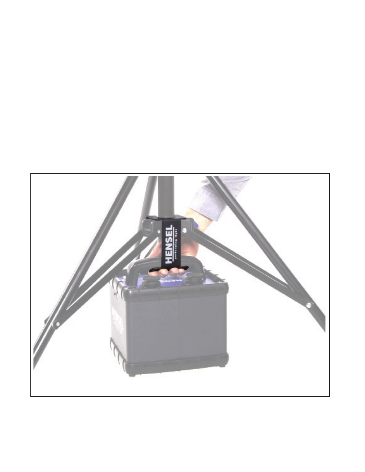
Doubly secure the equipment against dropping when mounting
it in a suspended fashion. According to the applicable safety
regulations, it is necessary to secure the units twice by using
a steel rope. This can be ordered from Hensel-Visit, see „14
Accessories“ on page 48.
ÂLead the steel rope through the generator’s handle and
through a suitable eyelet on the suspension.
The optional generator holder (see „14 Accessories“ on page
48) allows you to hook the generator to the bottom of a
lamp stand. Thus the stand has a lower center of gravity and
therefore, a more secure stand. This also protects the genera-
tor from possible moisture and dirt on the floor.
Suspended
mounting
Hooked to a
stand

User Manual Porty L
17
HENSEL-VISIT GmbH & Co. KG
Battery operation
ATTENTION!
Danger of explosion if the battery pack is handled improperly.
The battery flash generator must only be operated with genuine
Hensel lithium–ion batteries.
Batteries contain hazardous and caustic substances. Please note
the warning label on the battery.
The battery pack must not be opened or taken out of the
housing.
The battery pack must not be exposed to excessive heat like
sunshine, fire or such.
The battery pack must be protected from shock, vibration, and
moisture.
Battery pack removal and insertion
ÂSwitch off the Porty L using the power switch 18.
ÂPush down the unlocking device 23 on the battery pack and
pull the battery pack out of the unit’s front.
ÂPush the battery pack into the unit until you hear it lock into
place.
The charger Porty Lithium
ATTENTION!
The battery pack must only be charged with a genuine Hensel
charger Porty Lithium.
The micro chip controlled charger has an input voltage range
of 100-240 VAC. The charge time is 2 hours. After 45 minu-
tes, the battery has reached a charge level of 80% maximum
capacity.
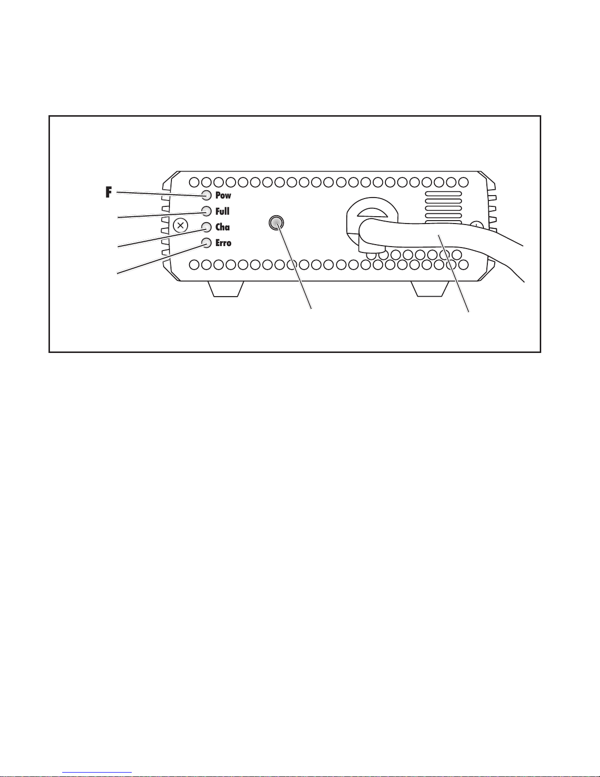
The charge level is indicated on the charge indicator E.
Removal
Insertion
User Manual Porty L
18
HENSEL-VISIT GmbH & Co. KG
Charging the battery is done via the charge socket located on
the battery 27. The battery can be inside or out of the Porty L
during charging.
A...... Charge cable
B...... Start charging Wake Up
C...... Error indicator Error (rot)
D...... Charge indicator Charging (yellow)
E...... Charge level indicator Full (green)
F...... Power check Power (red)
Power
Full
Charging
Error
Wake Up
A
B
C
D
E
F

User Manual Porty L
19
HENSEL-VISIT GmbH & Co. KG
Technical data
Charger unit type Charger Porty Lithium
Connector option: Porty L 600
Porty L 1200
Input voltage: Multivoltage (100-240 VAC)
Output voltage: max. 16.8 V
Output current: up to max. 8 A, automatic adjustment,
Short-circuit proof and inverse polarity
protected
Charging time: 100% ca. 2 h, 80% ca. 45 min.
Weight in kg (without mains
cable):
0,83 kg
Housing dimensions (LxWxH): 190 mm x 111 mm x 43 mm
Ventilation: active cooling via regulated ventilation
Scope of delivery: charger with fixed charge cable,
mains cable with country-specific plug
Code no.: 5672
Subject to technical changes.
The listed data are standard values which may deviate depending on component tolerances.
Connection and operation
The unit does not have a mains switch. It is ready when connec-
ted to a power supply. A status display allows you to monitor
the charge process.
ATTENTION!
The charger must only be connected to grounded power sup-
plies.
The charger Porty Lithium is only approved for the charging of
Porty L batteries.
ÂPlug in the included mains cable into the mains connector
socket (on the back) and connect the mains plug to the
power supply.
The mains check Power F lights up red.
ÂInsert the plug of the charger cable Ainto the charge socket
27 of the battery and lock the plug by turning it clockwise a
quarter of the way.
The yellow charge control Charging D is blinking.
User Manual Porty L
20
HENSEL-VISIT GmbH & Co. KG
ÂPress the Wake Up key B, to start the charging process.
When the battery is fully charged, the green charge indicator
Full E lights up.
ÂRemove the charge cable from the battery.
The charge capacity can also be checked via the charge indi-
cator on the battery. See „Battery charge status indicator“ on
page 20.
Note:
The battery should not be connected to the charger for longer
than 24 hours.
Due to a chemical reaction, the charger heats up while char-
ging. This is especially pronounced at the end of the charge pro-
cess when the battery feels warm. If the battery does not warm
up properly and gets really hot, the protective switch could be
faulty. In this case, remove the charger cable and have the bat-
tery checked by an authorized service center.
A possible charging error is indicated by a red error light C Error.
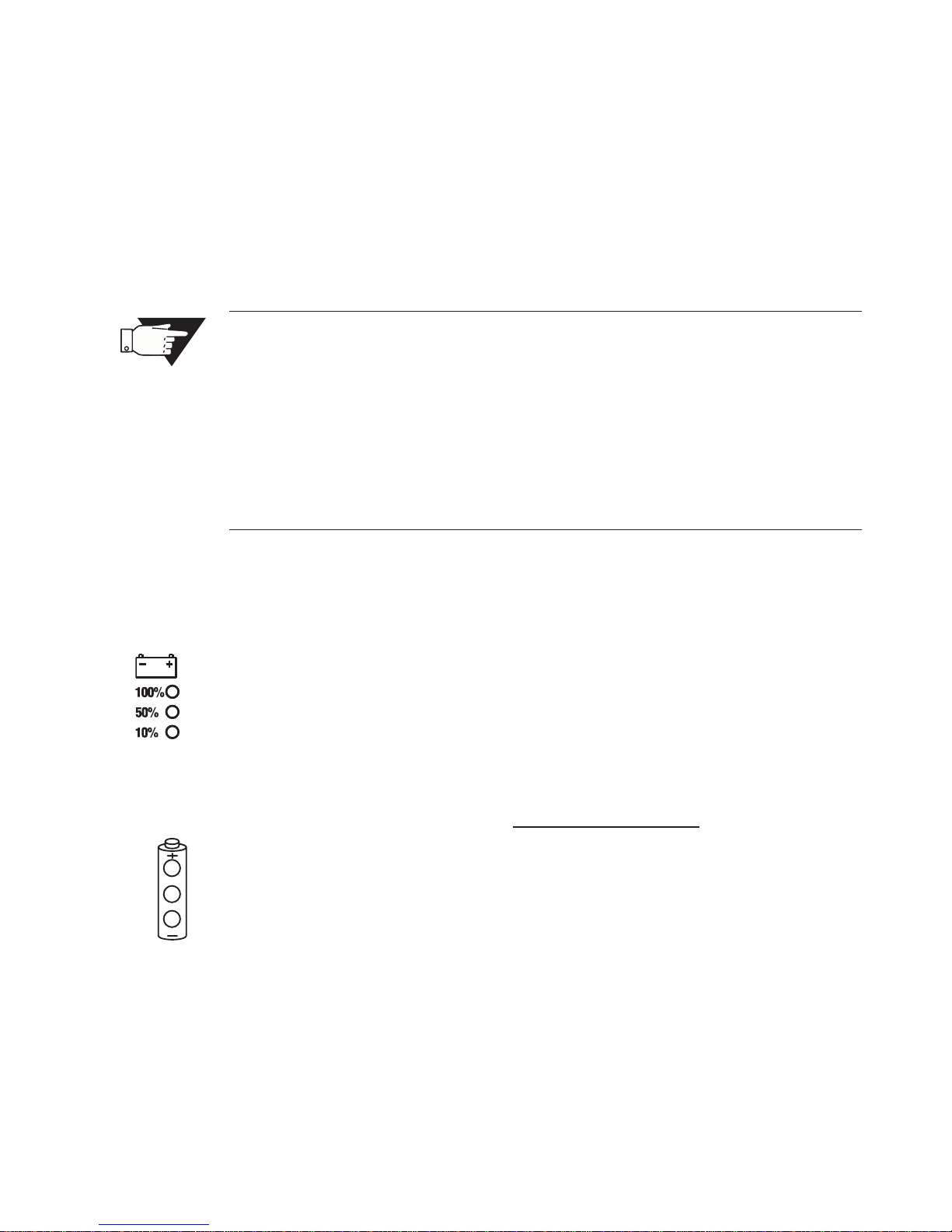
Battery charge status indicator
The charge status of the Porty L’s battery is shown on the batte-
ry charge status indicator 20. 3 LEDs indicate the charge capa-
cities 10%, 50% and 100%. Of course, these are only approxi-
mate values since the available number of flashes depends also
on factors like temperature, age of the battery, etc.
Charge status indicator while operating generator
The battery’s capacity can also be checked on the battery’s
charge status indicator 25. This is also possible when the gene-
rator is switched off.
ÂPress the CHECK key 26 on the battery drawer.
The capacity of the battery is indicated by a lit-up LED.
This manual suits for next models
2
Table of contents
Other Hensel Power Pack manuals


Popular Power Pack manuals by other brands


Yamaha
Yamaha BT7 owner's manual

Optoelectronics
Optoelectronics HBB056 user guide

Hama
Hama PD20-HD operating instructions

Alderon Industries
Alderon Industries FLEX quick start guide

LEI accessories
LEI accessories PORTABLE POWER PACK installation instructions

Magnaflux
Magnaflux CMD-2030 Series installation guide