HENWICK IP08-MX200 User manual

1080Pover IP 100M/1GbE with
Video Wall Processing
VER 1.1
Code: IP08-MX200
SKU: AV-VR-IP-TRN

Thankyou for purchasing thisproduct
For optimum performance and safety, please read these instructions carefully
before connecting, operating or adjusting this product. Please keep this manual
for future reference.
Surge protectiondevice recommended
This product contains sensitive electrical components that may be damaged
by electrical spikes, surges, electric shock, lighting strikes, etc. Use of surge
protection systems is highly recommended in order to protect and extend the
life of your equipment.
Table of Contents
1. Introduction...............................................................................................
2. Features .....................................................................................................
3. Package Contents ...................................................................................
4. Specifications............................................................................................
5. OperationControlsandFunctions .............................................................
5.1EncoderPanel......................................................................................
5.2DecoderPanel .....................................................................................
6. Rack MountingInstruction ........................................................................
6.14URack Mounting ................................................................................
6.21URack Mounting ...............................................................................
7. Encoder and Decoder Matching Settings................................................
8. Web GUI UserGuide ..................................................................................
9. SwitchModel ..............................................................................................
10.1080PoverIPSystemControl .....................................................................
11.ApplicationExample................................................................................
1
1
1
2
3
3
6
8
8
10
11
12
18
20
20

1. Introduction
2. Features
HDMI 1.3 and HDCP 1.4 compliant
Video resolution up to 1920x1200@60Hz 4:4:4
Support 4.95Gbps video bandwidth
Signal transmission distance can be extended up to 328ft / 100m via
CATE/6/6A/7 cable
Support point-to-point signal extension
Support signal distribution, multicast mode, distributed matrix and video
wall (up to 9 x 9) functions over a 1G Network Switch
Intelligent video wall management makes it achievable of novel layout of
wall congurations
Support LPCM 2.0CH (32/44.1/48KHz) audio format
Support audio embedding and extracting
Support RS-232 control (pass-through & Guest mode)
Support main stream and sub stream encoding modes
Stream parameters can be congured via Web GUI or Controller Box
Controlled via panel buttons, RS-232, TCP/IP, Web GUI and Controller Box
Support POE function (802.3af Class 3, PD mode)
Smart networking design for easy and exible installation
1/21
The AV over IP product distributes multiple HD contents to multiple HD display
devices over a 100M/1G Network Switch. It offers congurable high quality,
low-bandwidth H.265/H.264 congurable compression video and supports
resolution up to 1920x1200@60Hz 4:4:4. Signal transmission distance can be
extended up to 328ft / 100m via CATE5E/6/6A/7 cable. The product supports
analog audio embedding and extracting. It also supports RS-232 control
(pass-through & Guest mode) and single-machine control (without a Controller
Box, matrix switching can be realized with panel buttons or RS-232 control).
3. Package Contents
Qty Item
11080P over IP 100M/1GbE
Encoder
23-pin Phoenix Connector
(3.81mm, male)
4Machine Screw (KM3, 4mm)
2
12V/1A Locking Power Adapter1
1User Manual
or
Qty Item
11080P over IP 100M/1GbE
Decoder
2
3-pin Phoenix Connector
(3.81mm, male)
4
2
12V/1A Locking Power Adapter1
1User Manual
Mounting Ear Mounting Ear
Machine Screw (KM3, 4mm)

4. Specications
Connection
Decoder
Power Supply Input: AC100 - 240V 50/60Hz,
Output: DC 12V/1A
Operating
Temperature
Encoder: 2.88W, Decoder: 2.88W
Storage Temperature
14 - 113°F / -10 - 45°C
Relative Humidity
-4 - 140°F / -20 - 60°C
Power Consumption
20 - 90% RH (no condensing)
Weight Encoder: 74g, Decoder: 74g
1x HDMI OUT [Type A, 19-pin female]
1x LAN [RJ45 connector, POE]
1x AUDIO OUT [3-pin phoenix connector]
1x RS-232 [3-pin phoenix connector]
Dimensions
BlackColor
Encoder / Decoder:
120mm [W] x 95mm [D] x 21.5mm [H]
Mechanical
Metal enclosureHousing
Technical
HDMI Compliance HDMI 1.3
HDCP Compliance HDCP 1.4
Video Resolution Up to 1920x1200@60Hz 4:4:4
Color Space RGB4:4:4, YCbCr 4:4:4, YCbCr 4:2:2
Color Depth Input: 8-bit, 10-bit, 12-bit (1080p@60Hz);
Output: 8-bit
Audio Formats
LPCM 2.0CH (32/44.1/48KHz)
Video Bandwidth 4.95Gbps
Encoder
1x HDMI IN [Type A, 19-pin female]
1x LAN [RJ45 connector, POE]
1x AUDIO IN/OUT [3-pin phoenix connector]
1x RS-232 [3-pin phoenix connector]
2/21
Video Compression
Standard H.265/H.264
Transmission
Distance 100m (CAT5E/6/6A/7)

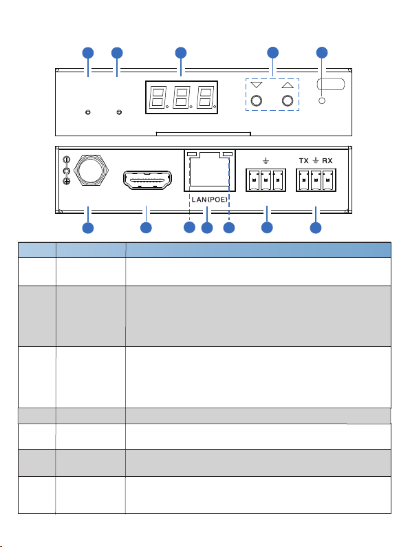
5. Operation Controls and Functions
5.1 Encoder Panel
No. Name Function Description
1POWER LED
(Red)
The LED ashes at 1 Hz during the system startup, and the
LED is always on after the startup is complete.
2LINK LED
(Green)
3/21
DC 12V RS-232
RL
AUDIO IN/OUTHDMI IN
CH SELECT R E S E T
POWER LINK
EN C
3
10 9
1 2 34 5
6
7
8
11
12
LED screen
Displays IP address, ID etc information.
Note: When clicking the SHOW ME option of the
corresponding machine on the Controller, the LED screen
of the corresponding machine will ash “SHO”, so that you
can nd the corresponding machine in the system.
Network connection status LED.
▪ Light on: Network is connected well, and there is compatible
signal (the resolution is less than 1920*1200, and the frame
rate is less than or equal to 60) access.
▪ Light ashes at 1Hz: Network is connected well, but there is
not video input.
▪ Light ashes at 10Hz: Network is connected well, but the
accessed signal is incompatible (resolution is greater than
1920*1200, or the frame rate is greater than 60).
▪ Light off: Network is not connected.

7 AUDIO IN/OUT
8 LAN (POE) 100M/1G Network port. Connect to a Switch/Router/Hub for
data transmission or POE function.
10
Link Signal
Indicator lamp
(Green)
RS-232 RS-232 serial port, supporting signal pass-through and local
serial port control.
6
▪ Illuminating: The network cable is connected normally.
▪ Dark: The network cable is not connected well.
11 HDMI IN HDMI input port, connect to an HDMI signal source device
such as DVD or Set-top box with an HDMI cable.
4/21
4 CH SELECT
5 RESET System reset button. Press and hold this button for 5
seconds, the system will restart and restore factory Settings.
9
Data Signal
Indicator lamp
(Yellow)
▪ Flashing: There is data transmission.
▪ Dark: There is no data transmission.
12 DC 12V
Used to set Encoder ID and other settings.
AUDIO IN: Analog stereo audio input port. Connect to an
audio input source device.
AUDIO OUT: Analog stereo audio output port. Connect to an
audio output device.
The device can be powered via two methods:
▪ Local DC 12V/1A power supply;
▪ POE from Network Switch. Device acts as PD mode.
When the Switch supports POE function, DC power supply
is not needed.
Description of the LED screen and CH SELECT buttons (For the Encoder).
1, After the system is powered on, the Encoder’s LED screen will show the ENC ID (000
by default if not set)
2
Pressandhold the UP button for 5 seconds, the Encoder’s LED screen will show in
sequence “IP:", "xxx", "xxx", "xxx", "xxx", which is the IP address of the Encoder.
3, Press and hold UP + DOWN buttons at the same time for 5 seconds, then release to
enter the “Conguration” mode with “CFN” displaying on the LED screen.
Note:
Encoder can choose HDMI audio input or external audio embedding. It can be set
through the CH SELECT buttons on the front panel of the Encoder. (The default setting
is HDMI audio input.)
If it is set to HDMI audio input, the L/R OUT output of Encoder is HDMI audio loop out.
If it is set to external audio embedding, the L/R IN input of Encoder is the input of
external audio embedding, and the L/R OUT output is the external audio embedding
loop out.

5/21
EDID ID EDID Description
00
01
02
03
04
05
06
H1080P60_2CH
H720P60_2CH
H1200P60_2CH
D1080P60
D1200P60
USER1
USER2
Notes:
(1) H refers to HDMI; D refers to DVI. (The default EDID of 1080p60 will be used if you
have not previously copied the EDID to ID 06 or downloaded EDID to ID 07/08 on
the controller box web page.)
(2) EDID ID 06/07/08 is not available without Controller Box.
6, For audio options settings, press the UP or DOWN button until the LED screen shows
“AHE” (in which “A” refers to Audio and “HE” to HDMI EMB). Press and hold UP +
DOWN buttons for 5 seconds, then release to enter the “AUDIO Settings” mode. The
audio option (AHE or AEI) on the LED screen will ash at 1Hz, then press the UP or
DOWN button to select the AUDIO option, then press and hold UP + DOWN buttons
for 5 seconds to conrm the setting and stop ashing.
The corresponding audio options are as follows:
AHE: Use HDMI Audio
AEI: Use external Audio In
4, For Channel ID settings, press the UP or DOWN button to display the current ID
number (e.g. 001) on the LED screen. Press and hold UP + DOWN buttons for 5
seconds, then release to enter the “ID Settings” mode. The ID number (e.g. 001) on
the LED screen will ash at 1Hz, then press the UP or DOWN button to select the
Channel ID you desired, then press and hold UP + DOWN buttons for 5 seconds to
conrm the setting and stop ashing.
5, For EDID ID settings, press the UP or DOWN button until the LED screen shows
“E00” (in which “E” refers to EDID
“00”toEDID ID). Press and hold UP + DOWN
buttons for 5 seconds, then release to enter the “EDID Settings” mode. The EDID ID
number (e.g. E01) on the LED screen will ash at 1Hz, then press the UP or DOWN
button to select the EDID ID you desired, then press and hold UP + DOWN buttons
for 5 seconds to conrm the setting and stop ashing.
The corresponding EDID ID is as follows:
D1024P60
07
08
COPY
5.2 Decoder Panel
6/21
DC 12V RS-232
RL
AUDIO OUTHDMI OUT
CH SELECT R E S E T
POWER LINK
DE C
10 9
No. Name Function Description
1POWER LED
(Red)
2LINK LED
(Green)
3 LED screen
Displays IP address, ID etc information.
Note: When clicking the SHOW ME option of the
corresponding machine on the Controller, the LED screen of
the corresponding machine will ash “SHO”, so that you can
nd the corresponding machine in the system.
4Used to set Decoder ID and other settings.
CH SELECT
5 RESET System seset button. Press and hold this button for 5
seconds, the system will restart and restore factory Settings.
1 2 34 5
12 11 876
7 AUDIO OUT
Analog stereo audio output port. Connect to an amplier or
loudspeaker through a 3-pin phoenix connector. It follows
the audio output of the Encoder.
RS-232 RS-232 serial port, supporting signal pass-through and local
serial port control.
6
Network connection status LED.
▪ Light on: Network is connected well, and there is video data.
▪ Light ashes: Network is connected well, but there is no video
data.
▪ Light off: Network is not connected.
The LED ashes at 1 Hz during the system startup, and the
LED is always on after the startup is complete.

7/21
8LAN (POE) 100M/1G Network port. Connect to a Switch/Router/Hub for
data transmission or POE function.
10
11 HDMI OUT HDMI output port, connect to an HDMI display device such as
TV or monitor.
9
12 DC 12V
Link Signal
Indicator lamp
(Green)
▪ Illuminating: The network cable is connected normally.
▪ Dark: The network cable is not connected well.
Data Signal
Indicator lamp
(Yellow)
▪ Flashing: There is data transmission.
▪ Dark: There is no data transmission.
The device can be powered via two methods:
▪ Local DC 12V/1A power supply;
▪ POE from Network Switch. Device acts as PD mode.
When the Switch supports POE function, DC power supply
is not needed.
Description of the LED screen and CH SELECT buttons (For the Decoder).
1, After the system is powered on, the Decoder’s LED screen will show the ID of the
connected Encoder (000 by default if not set).
2
Pressandhold the UP button for 5 seconds, the Decoder’s LED screen will show in
sequence “IP:", "xxx", "xxx", "xxx", "xxx", which is the IP address of the Decoder.
3, Press and hold UP + DOWN buttons at the same time for 5 seconds, then release to
enter the “Conguration” mode with “CFN” displaying on the LED screen.
4, For Channel ID settings, press the UP or DOWN button to display the current ID
number (e.g. 001) on the LED screen. Press and hold UP + DOWN buttons for 5
seconds, then release to enter the “ID Settings” mode. The ID number (e.g. 001) on
the LED screen will ash at 1Hz, then press the UP or DOWN button to select the
Channel ID you desired, then press and hold UP + DOWN buttons for 5 seconds to
conrm the setting and stop ashing.
5, For output resolution settings, press the UP or DOWN button until the LED screen
shows “S00” (in which “S” refers to Scaler and “00” to resolution ID), then press and
hold UP + DOWN buttons for 5 seconds, then release to enter the “Output Resolution
Settings” mode. The Resolution ID number (e.g. S01) on the LED screen will ash at
1Hz, then press the UP or DOWN button to select the Resolution ID you desired, then
press and hold UP + DOWN buttons for 5 seconds to conrm the setting and stop
ashing.

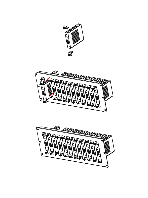
6. Rack Mounting Instruction
This product can be mounted in a standard 4U rack (Please contact your
supplier for 4U rack sale). The mounting steps are as follows:
6.1 4U Rack Mounting
Resolution ID Resolution Description
00
01
02
03
04
05
06
Pass Through (default)
1080P60
1080P50
1080P30
1080P25
1080P24
720P60
07 720P50
08
09
10
11
12
13
14
576P50
480P60
640X480P60
800X600P60
1024X768P60
1280X800P60
1280X1024P60
15 1366X768P60
16
17
18
19
1440X900P60
1600X1200P60
1680X1050P60
1920X1200P60
The corresponding output resolution ID is as follows:
8/21
9/21
Step 1: Use included screws to x two mounting ears on the product, as
shown in the gure below:
Step 2: Insert the product with mounting ears into a 4U rack (up to 12 units
can be installed vertically), as shown in the gure below:
Step 3: Use screws to x mounting ears on the rack to complete the mounting,
as shown in the gure below:

10/21
6.2 1U Rack Mounting
This product also can be mounted in a standard 1U rack (up to 8 units can be
installed horizontally). The mounting steps are as follows:
Step 1: Stack two products on top of each other, then use included screws
to x two 1U rack panels on the products, as shown in the gure below:
Step 2: Fix two 1U rack panels on another two stacked products in the same
way, then use screws to x two 1U rack panels together, as shown in
the gure below:
Step 3: Fasten screws between two 1U rack panels, so that eight products
are mounted in a 1U rack, as shown in the gure below:

7. Encoder and Decoder Matching Settings
When multiple Encoders and Decoders are in the system without a Controller
Box, it is necessary to match them well rstly. You can match all Encoders and
Decoders in following two methods.
Method 1: Use the CH SELECT buttons on the front panel of the Encoder/
Decoder.
According to the methods mentioned in Chapter 5, set the ID of Encoder, then
set the ID of Decoder, nally set the Encoder ID from which to subscribe the
stream. Match all Encoders and Decoders in the same way.
Method 2: Use the RS-232 serial port command control.
Connect the RS-232 port of Encoder/Decoder to a PC or control system, as
shown in the gure below. Then use a Serial Command tool on PC to send
the RS-232 command code: “!OUT xxx FR yyy\r\n”. The function of this
command is to connect the Decoder (ID:xxx) to the Encoder (ID:yyy). Match
all Encoders and Decoders in the same way.
RS-232to USB cable
TX
Ground
RX
3-pinPhoenix Connector
RS-232
PC
11/21

DC1 2V RS-232
RL
AUD IOOU THD MIOU T
DC1 2V RS-232
RL
AUD IOOU THD MIOU T
DC1 2V RS-232
RL
AUD IOOU THD MIOU T
12/21
PC
ENC 2
ENC 10
DEC 1
DEC 2
DEC 10
CAT5E/6/6A/7
ENC 1
Switch
8. Web GUI UserGuide
You can use the built-in Web GUI to congure all products through a Switch.
The operation method is shown as below.
Step 2: Connect the PC and IP products you need to congure to a Switch.
The connection diagram is shown as below.
DC1 2V RS-232
RL
AUDIOIN/ OUTHD MIIN
DC1 2V RS-232
RL
AUDIOIN/ OUTHD MIIN
DC1 2V RS-232
RL
AUDIOIN/ OUTHD MIIN
Step 1: Match all Encoders and Decoders as described in Chapter 7.

Step 3: Press and hold the (CH SELECT) UP button on the front panel of the
Encoder/Decoder for 5 seconds to check the IP address. (Please refer to
Chapter 5 for details.)
Step 4: Set the PC’s IP address to be in the same network segment with the
Encoder/Decoder, for instance, set the IP address to be 169.254.3.150 and
Subnet mask to be 255.255.0.0.
13/21
Step 5: Input the IP address of the Encoder/Decoder into the browser on PC to
enter the Web GUI login interface.
Step 6: Input the default User “admin” and the default Password “admin”,
and then click “Log In” to enter the Web GUI interface.
10
169 168 1 30

14/21
On this page, you can congure the video properties as required.
■ Device Information Page
The Web GUI function pages are shown as below:
The Status page provides basic information about the Encoder/Decoder, such
as Firmware Version, IP Address, Subnet Mask, Gateway and MAC Address.
■ Video Conguration Page

15/21
Main Stream: You can congure Video Encoding Format, Audio Encoding
Format and Bitrate. Video Encoding Format supports H.264 and H.265
(H.265 by default). Audio Encoding Format supports PCM and AAC (PCM
by default). Encoding Resolution cannot be set, it follows the input resolution.
The default Bitrate is 8Mb/s.
Sub Stream: You can congure Video Encoding Format, Resolution and
Bitrate. Video Encoding Format supports H.264 and H.265 (H.265 by default).
The default Encoding Resolution is 640*360. The default Bitrate is 1Mb/s.
ID Setting: You can congure the ID of the Encoder. (After setting the ID,
the IP will change. You need to press and hold the (CH SELECT) UP button
on the front panel of the Encoder for 5 seconds to check the IP address, and
then re-enter the new IP address on the web page to continue setting).
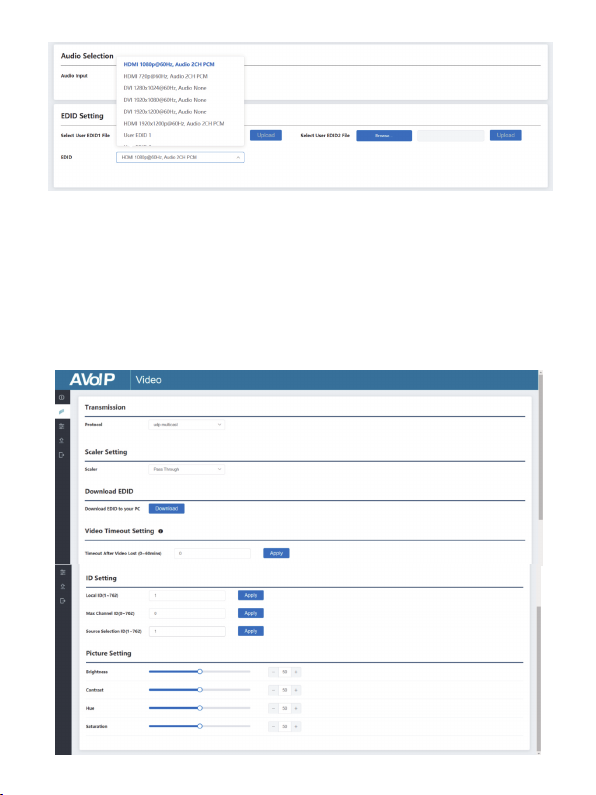
Audio Selection: You can congure the Audio Input HDMI/Anologue).
EDID Setting: You can choose an EDID option from the drop-down list as
shown in the below gure.
Encoder Video Conguration
Encoder video conguration page includes Main Stream, Sub Stream, ID
Setting
AudioSelection and EDID Setting.
Decoder Video Conguration
Decoder video conguration page includes Trasmission Protocol, Scale
Setting, Download EDID, Video Timeout Setting, ID Setting and Picture
Setting.
User EDID 1 and User EDID 2 can be uploaded in Select User EDID1 File
and Select User EDID2 File, and the content of the uploaded binary le is
EDID. (This le can be downloaded from the Download EDID of the Decoder
Video page.)
16/21
17/21
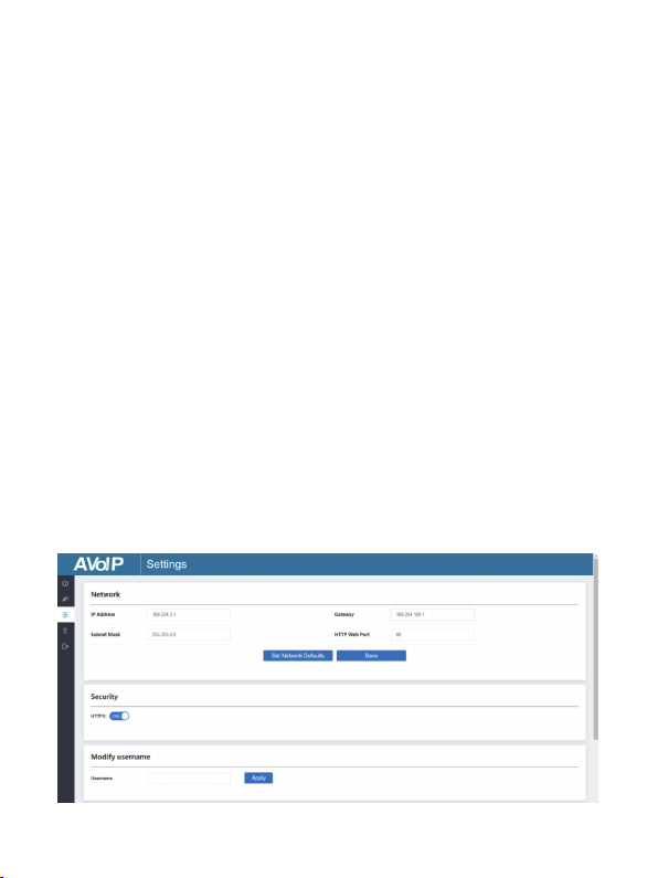
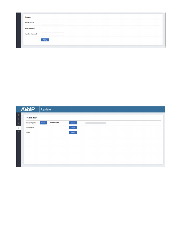
On this page, you can set Network settings, congure Security Module, modify
username and Login Password as required.
■ Settings Page
Transmission Protocol: You can select “udp unicast” or“udp multicast”
(udp multicast by default).
Scaler Setting: You can set the output resolution (Pass Through by default).
Download EDID: You can download the EDID binary le of the display device
connected to the Decoder. The EDID le can be used as the User EDID le to
be uploaded to the Encoder.
Video Timeout Setting: You can set the timeout to turn off the video output
when no input video signal is detected. 0 means never close.
ID Setting:
Local ID: You can set the ID of the Decoder. (After setting the ID, the IP will
change. You need to press and hold the (CH SELECT) UP button on the front
panel of the Decoder for 5 seconds to check the IP address, and then re-enter
the new IP address on the web page to continue setting).
Max Channel ID: You can set the maximum range of Source Selection ID that
can be set. When it is set to 0, there is no limit to the setting range of Source
Selection ID.
Source Selection ID: You can select the ID of the Encoder to be the input
source.
Picture Setting: You can congure the picture parameters (Brightness,
Contrast, Hue and Saturation)
18/21
Click “Browse..” to import the upgrade le and click “Update” to start upgrade.
There will be a progress bar prompt during the upgrade process. When the
progress bar reaches 100%, it indicates the upgrade is successful, and the
device will be restarted automatically.
Clicking “Reset” can reset the device to factory default settings.
Clicking “Reboot” can reboot the device.
Notes:
(1) The Network Settings can be set only when the Mode button is set to Static.
(2) All changes will take effect by clicking “Save” below.
(3) After any changes to the Network Settings, username or Login Password,
it will redirect to the Web browser home page or the Web GUI login interface.
You need to log in the Web GUI again with the new settings.
■ Update Page
This manual suits for next models
1
Table of contents


