herdstar BinTrac Breeder Control User manual

Operation Manual
Version 2.0 1 Part Number MAN-000009
Breeder Control
Operation Manual
Patented
U.S. Patent No. 7,980,129, Patent No. 8,581,122, Patent No. 8,853,566
U.S. Patent No. 9,310,243, Patent No. 9,651,413, Patent No. 10,082,421
Canada Patent No. 2,822,294
Korea Patent No. 1900521

Operation Manual
Version 2.0 2 Part Number MAN-000009
1400 Madison Avenue Suite 504, Mankato, MN 56001
PH: 507-344-8005 FAX: 507-344-8009
www.herdstar.com
Table of Contents
Overview..........................................................................................................................................................................3
Components.................................................................................................................................................................3
Features .......................................................................................................................................................................3
About This Manual............................................................................................................................................................4
Configurations .............................................................................................................................................................. 4
System Settings................................................................................................................................................................7
Accessing the Setup mode...........................................................................................................................................7
Navigating Setup mode................................................................................................................................................7
Selecting an Option in Setup mode..............................................................................................................................7
Options in Setup Mode.................................................................................................................................................7
Setup and Operation.......................................................................................................................................................12
Gain-In-Weight (Load Batch Method) ........................................................................................................................12
Overview................................................................................................................................................................12
Setup Parameters..................................................................................................................................................13
System Settings in Setup Mode.............................................................................................................................13
Startup ...................................................................................................................................................................16
Operation...............................................................................................................................................................16
Wiring Diagram......................................................................................................................................................18
Loss-In-Weight (Unload Batch Method).....................................................................................................................19
Overview................................................................................................................................................................19
Setup Parameters..................................................................................................................................................20
System Settings in Setup Mode.............................................................................................................................20
Startup ...................................................................................................................................................................23
Operation...............................................................................................................................................................23
Wiring Diagram......................................................................................................................................................25
Inventory Bin with Dual Breeder Console Unloads....................................................................................................26
Overview................................................................................................................................................................26
Setup Parameters..................................................................................................................................................27
System Settings in Setup Mode - MASTER ..........................................................................................................27
System Settings in Setup Mode - REMOTE..........................................................................................................31
Startup ...................................................................................................................................................................33
Operation...............................................................................................................................................................33
Wiring Diagram......................................................................................................................................................36
Weigh Bin with Dual Breeder Consoles for Programmed Fill and Batch Configuration.............................................37
Overview................................................................................................................................................................37
Setup Parameters..................................................................................................................................................38
System Settings in Setup Mode - MASTER ..........................................................................................................38
System Settings in Setup Mode - REMOTE..........................................................................................................42
Startup ...................................................................................................................................................................44
Operation...............................................................................................................................................................44
Wiring Diagram......................................................................................................................................................47
Service............................................................................................................................................................................48
Maintenance and Repair............................................................................................................................................48
Troubleshooting..........................................................................................................................................................48
Flashing Fill............................................................................................................................................................48
Flashing Set.LC .....................................................................................................................................................48
Load Batch Does Not Start....................................................................................................................................48
BinTrac Breeder Control Blank..............................................................................................................................48
Inaccurate Weight Readings..................................................................................................................................49
Error Messages......................................................................................................................................................49
Load Cell Troubleshooting Procedures .................................................................................................................51
HerdStar BinTrac®Warranty...........................................................................................................................................52
is a trademark of HerdStar, LLC.
Copyright © 2019 HerdStar, LLC. All rights reserved.
Printed in the USA

Operation Manual
Version 2.0 3 Part Number MAN-000009
Thank you for purchasing a BinTrac Breeder Control from HerdStar, LLC.
Overview
Your BinTrac Breeder Control provides a cost-effective way to automatically monitor bin
level and batch a programmed load or unload amount.
Components
A BinTrac Breeder Control consists of a few basic components:
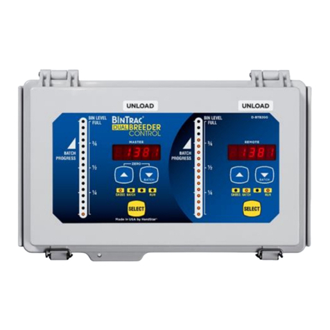
BinTrac Breeder Control
This is the main unit of the BinTrac system. The BinTrac Breeder Control communicates
with the Smart Summing Boxes to register the weight of material in the bins. The material
level is computed and displayed on the LED bar graph.
Load Cell Bracket
Four or more load cell brackets allow the BinTrac system to accurately measure the material weight in your bins. The
Smart Summing Box averages the signals from all brackets to minimize errors that could result from voids (holes) in
the material.
Smart Summing Box
A single Smart Summing Box per bin communicates the current reading on the leg brackets to the BinTrac Breeder
Control.
BinTrac Power Supply
This provides the power for the BinTrac Breeder Control. The power supply converts the line voltage to low voltage.
BinTrac Breeder Control Remote Display
A BinTrac Breeder Control Remote Display is a standard BinTrac Breeder Control indicator configured as a Remote
Display. A hardwire cable must connect the Remote Display to the Master BinTrac Breeder Control. Required for
dual Breeder Control configurations.
BinTrac Remote Display (Optional)
A BinTrac Remote Display is a standard BinTrac Indicator configured as a Remote Display. A hardwire cable must
connect the Remote Display to the Master BinTrac Breeder Control.
Features
Weight Display
The BinTrac Breeder Control displays the gross weight of the bin and its level.
Batch Run
The BinTrac Breeder Control features a relay to enable a load or unload system for batching a programmed amount.
Fill Events
The BinTrac Breeder Control records the net weight increase of the last four fill events.
24-Hour Usage
The BinTrac Breeder Control records the last four operational 24-hour usage amounts.
Remote Display
A BinTrac Indicator is configured as a Remote Display which will display the same updated weight information from
the host Breeder Indicator.

Operation Manual
Version 2.0 4 Part Number MAN-000009
About This Manual
The BinTrac Breeder Control Operation Manual is divided into a few different sections:
•System Settings –This section covers how to access and navigate the SETUP menu. It gives a basic
overview of what each setting is used for.
•Setup and Operation –This section covers the specific setup and operation instructions for each
configuration that is possible with the BinTrac Breeder Control. Refer to Configurations below to determine
which configuration is appropriate for your scenario.
•Service –This section covers the basic maintenance of the BinTrac Breeder Control system as well as
troubleshooting should problems arise.
Configurations
The BinTrac Breeder Control can be used in different configurations based on your needs. Before beginning the
setup of your system, determine which configuration you will be using. Below is an overview of the four different
configurations of batching. After determining the appropriate configuration, proceed to the portion of the manual for
that specific configuration by using the noted page numbers.
Gain-In-Weight (Load Batch Method)
Pages 12 - 18
The BinTrac Breeder Control System allows the user to select the amount of feed required for the day. The BinTrac
Breeder Control System controls a conveying system to deliver feed from the Inventory Bin to the Weigh Bin. The
Weigh Bin weighs the feed delivered and the BinTrac Breeder Control System stops the delivery when the required
amount of feed has been delivered to the Weigh Bin. In this configuration, the system batches into the weigh bin until
the total weight (gross weight) equals the target batch amount.

Operation Manual
Version 2.0 5 Part Number MAN-000009
Loss-In-Weight (Unload Batch Method)
Pages 19 - 25
The Loss-In-Weight (Unload Batch Method) allows the user to select the target batch amount of feed required for
the day. The BinTrac Breeder Control System will enable the hopper or feed line fill system allowing the feed line
system to transfer the feed into the house until the required amount of feed has been delivered. In this
configuration, this system batches and unloads until the batch target amount is unloaded from the bin.
Inventory Bins with Dual Breeder Console Unloads
Pages 26 - 36
Dual Breeder Consoles can be connected to a single inventory bin for programmed batching of two independent
amounts on separate delivery systems. The system can be used for both rooster (Master) and hen (Remote)
feeding by enabling/disabling the appropriate feed delivery system. The system features an auto/manual override
feature for each auger via an external switch.

Operation Manual
Version 2.0 6 Part Number MAN-000009
Weigh Bin with Dual Breeder Consoles for Programmed Fill and Batch
Pages 37 - 47
This configuration provides automated filling and batching of hen feed using a weigh bin. A Remote Breeder
Console provides automated filling of a programmed gross weight amount into a weigh bin. A Master Breeder
Console provides automated loss-in-weight batching of a programmed amount for the hen feeding. There is an
auto/manual override feature for each auger via an external switch.

Operation Manual
Version 2.0 7 Part Number MAN-000009
System Settings
The SETUP mode is used to configure the different settings and parameters of the BinTrac
Breeder Control.
Note: If there is no activity for a period of time while in SETUP mode, the system will exit
SETUP mode and return to Weight Display mode.
Accessing the Setup mode
1. Press and hold the SELECT button down until is displayed.
Segmented display:
Navigating Setup mode
To navigate through the options in SETUP mode, use the and keys to cycle through the
options/parameters. Refer to the SETUP menu flow chart to the right.
Selecting an Option in Setup mode
To select an option/parameter to edit in SETUP mode, you must navigate to the option
you wish to edit using the and keys. Press the SELECT key when you reach the desired
option.
Options in Setup Mode
In the SETUP Mode, the four LEDs indicate configuration options as being enabled
(solid on) or disabled (flashing).
GROSS WEIGHT - Configures a BinTrac or Breeder Indicator as a Remote
Display automatically when connected to a Master Breeder
Control with Peripheral Devices enabled.
BATCH AMT - NOT USED
LED (left of RUN) - NOT USED
RUN - Enable communications to Peripheral devices.
Must be enabled when Breeder Control is connected to a
Remote Display device (REMOTE BinTrac or Breeder Control
console).
SETUP Menu
Flow Chart

Operation Manual
Version 2.0 8 Part Number MAN-000009
Batch
Enables you to set the batch option to LoAd or u.LoAd (unload). LoAd is used when you want material batched into
a bin. Based on the gross weight of the bin, material is batched into the bin until the batched amount equals the gross
amount. u.LoAd is used when you want material batched out of a bin. In this case, the bin is holding a bulk amount of
feed and will batch out the programmed batch amount.
1. Press the SELECT key to enter menu.
2. Use the or keys to select or ..
Segmented display:
Rated Value
The average rated output in millivolt/volt (mV/V) of the load cells. If using load cells other than the HerdStar load
cells, you may need adjust this value appropriately.
*IMPORTANT –DO NOT change this setting from the default of 3.000 if you are using HerdStar load cells.
1. Press the BIN key to select the desired bin.
2. Use the UPPER key to increase the rated output by 0.001.
3. Use the LOWER key to decrease the rated output by 0.001.
Segmented display:
Load Cell Capacity Value
Sets the total capacity of each bin. The total capacity is the sum of all the load cells rated capacity. This can be
calculated by multiplying the capacity of individual load cells by the number of legs on the bin. Example: A four-
legged bin using 10k load cells would result in an L.C.CAP setting of 40000.
Note: When setting up for kilograms, convert the total capacity to kilograms.
1. Press the BIN key to select the desired bin.
2. Use the UPPER key to increase the value by 1 lb.
3. Use the LOWER key to decrease the value by 1 lb.
Segmented Display:

Operation Manual
Version 2.0 9 Part Number MAN-000009
Increment Value
Sets the increment that the bin weight will be rounded to. The reading from a bin
is rounded to the nearest multiple of the increment, using standard rounding rules.
The possible values are: 1, 2, 5, 10, 20, 50, 100, 200, 500, 1., 2.,5.,10.,20., and 50..
Example: If an increment of 10 is selected and the net value of a bin’s weight is
11,314 lbs., the segmented display will read 11310. Refer to Figure 1 for more
examples based on a net weight of 11,314 pounds.
Note: When the increment value is followed by a “.”,the displayed weight
value is then scaled by 10. For example, an increment value of 1. would cause
120462 pounds to show as 12046. on the display. This is required when the
displayed weight will exceed the 5 available digits on the BTB200.
1. Press the BIN key to select the desired bin.
2. Use the UPPER key to increase the increment value.
3. Use the LOWER key to decrease the increment value.
Segmented display:
Full Value
Sets the weight of a full bin. This is for calibration of the LED bar graph level. The
value dictates at what net weight the bar graph will display completely full (all 16 LEDs lit).
1. Press the BIN key to select the desired bin.
2. Use the UPPER key to increase the value by 1 lb.
3. Use the LOWER key to decrease the value by 1 lb.
Segmented display:
Zero Value
Sets the weight of the empty bin. This value can also be set in the Operation Settings. This is used to compensate for
the empty weight of the bin to give an accurate value for the net weight of the material inside the bin.
Example: A bin weighs 1,200 lbs. empty. By setting the zero value to 1200, the BinTrac indicator calculates the
material weight as the total weight less the zero-weight value.
Note: If the bin was zeroed on the Indicator by pressing and holding the UPPER and LOWER keys (see Page
16 –Startup step 5), this field will display the automatically calculated amount.
1. Press the BIN key to select the desired bin.
2. Use the UPPER key to increase the value by 1.
3. Use the LOWER key to decrease the value by 1.
Segmented display:
incr
Display
1
11314
2
11314
5
11315
10
11310
20
11320
50
11300
100
11300
200
11400
500
11500
1.
1131.
2.
1132.
5.
1130.
10.
1130.
20.
1140.
50.
1150.
Figure 1

Operation Manual
Version 2.0 10 Part Number MAN-000009
Year
Sets the current year.
Segmented display:
Month
Sets the current month.
Segmented display:
Date
Sets the current date.
Segmented display:
Hour
Sets the current hour in 24-hour format.
Segmented display:
Minute
Sets the current minute
Segmented display:
Station ID Value
Sets the Station ID of the device. When interfacing the device to a Communication Hub (CH100), set this value from
1 to 127. Each BinTrac device must have a unique Station ID.
1. Press the BIN key to select the desired bin.
2. Use the UPPER key to increase the value by 1.
3. Use the LOWER key to decrease the value by 1.
Segmented display:
Software Version
Displays the Breeder Control programmed software version number.
1. Press the BIN key to see the software version number.
Segmented display:

Operation Manual
Version 2.0 11 Part Number MAN-000009
Smart Summing Box Software Version (Version 3.0 and higher)
Displays the software version number of each of the connected Smart Summing Boxes. This number may be
required if technical help is needed.
1. Press the BIN key to see the software version for each enabled bin.
Segmented display:
End
Allows the user to exit SETUP mode.
1. Press the BIN button to exit SETUP mode.
Segmented display:

Operation Manual
Version 2.0 12 Part Number MAN-000009
Setup and Operation
Gain-In-Weight (Load Batch Method)
Overview
The BinTrac Breeder Control allows the user to select the amount of feed required for the day.
The control activates a fill system to deliver feed from the Inventory Bin to the Weigh Bin. The
Weigh Bin is equipped with load cells to weigh the incoming feed. Once the total amount of
feed (Gross Weight) is loaded into the Weigh Bin, the Breeder Control shuts down the
incoming fill line.

Operation Manual
Version 2.0 13 Part Number MAN-000009
Setup Parameters
Follow the system wiring diagram (Page 18) to aid in the installation process, including supplied relays and switches.
Once installation is completed, the BinTrac Breeder Control unit must be programmed as summarized below:
1. The BinTrac Breeder Control console controls the batching from the inventory bin into the weigh bin (steps 1
through 19).
Access SETUP mode and configure the following:
•Set the Batch type to Load Batching
•Set an L.C.CAP value that matches the total capacity of all load cells
•Set a FuLL value that matches the maximum capacity of the weigh bin
•Set the Hour time parameter (default is CST Zone)
System Settings in Setup Mode
The SETUP mode is used to configure the one-time system setup settings for the appropriate
configuration. The following SETUP parameters MUST be correctly configured to ensure proper
operation and weighing:
•BATCH
•L.C.CAP
•FULL
•ZERO
•HOUR
NOTE: When first powering on the unit, .will be displayed. This is simply a reminder that
the load cell capacity for the system must be entered in the SETUP menu to ensure proper weighing
calibration.
NOTE: If there is no activity for a period of time while in SETUP mode, the system will exit and return
to the Weight Display mode.
Navigating Setup Mode
To navigate through the options in SETUP mode, use the and keys to cycle through the
options/parameters. See the SETUP menu flow chart to the right.
Accessing the Setup Mode
1. Press and hold the SELECT button down until is displayed.
Segmented display:
2. Press the key and will be displayed.
SETUP Menu
Flow Chart

Operation Manual
Version 2.0 14 Part Number MAN-000009
Batch
Enables you to set the batch option to LoAd or u.LoAd. In this configuration, the parameter MUST be set for LoAd
to batch from the inventory bin into the weigh bin.
Segmented display:
3. Press the SELECT key to enter BATCH menu, and .should be displayed. Press to set to .
4. Press the SELECT key and then is shown.
5. Press and . . is displayed.
Capacity (L.C.CAP)
The load cell system capacity is the sum of all the load cells rated capacity in either pounds or kilograms. This
parameter sets the calibration of the system. To determine this value, multiply the number of load cells by their
capacity.
Example: A four leg bin with 5k load cells would require an L.C.CAP setting of 20000 pounds.
Segmented display:
6. Press the SELECT key. The display will show the current setting (default is 30000).
7. Use the and keys to increase or decrease the value. Hold the key down to increase/decrease quickly.
8. Upon setting the appropriate value, press SELECT and the display will show .
9. Press the key and is displayed.
Full Value
This value is the maximum weight of a full bin in either pounds or kilograms as is for calibration of the LED bar graph
level. The value determines at what weight the bar graph will display completely full (all 16 LEDs lit). Set this to the
maximum amount of feed that you would consider the bin to be full.
Segmented display:
10. Press the SELECT key.
11. Use the and keys to increase or decrease the value. Hold the key down to increase/decrease quickly.
12. Upon setting the appropriate value, press SELECT and the display will show .

Operation Manual
Version 2.0 15 Part Number MAN-000009
Zero Value
Sets the weight of the empty bin in either pounds or kilograms. Convenient when wanting to calibrate a system when
a small amount of feed is already in the bin. The zero value is used to compensate for the empty weight of the bin to
give an accurate value for the net weight of the material inside the bin. The Breeder Control calculates the material
weight as the total weight less the zero (empty) weight value.
Example: A bin weighs 1200 pounds empty. In standard operation mode, simply press and hold on both the
and keys until displays. This would then set the zero value in the SETUP mode to 1200.
Segmented display:
13. Press the SELECT key. The current zero value is shown. If zeroed in standard operation mode, simply record
this value for future reference. If you need to adjust this value, use the and keys until the desired value
for an empty bin is shown.
14. Press the SELECT key and is displayed.
15. Press the key three times until is displayed.
Hour
Sets the current hour in 24-hour (military) format. The default hour is set to CST and should be adjusted, if necessary,
for your time zone.
Segmented display:
16. Press the SELECT key and the current hour is displayed. Use the and keys to enter the proper hour in
24-hour format.
17. Once the proper value is displayed, press SELECT and is displayed.
18. Press the key four times until is displayed.
End
Allows the user to exit SETUP mode.
19. Press the SELECT button while is displayed to exit SETUP mode.
Segmented display:

Operation Manual
Version 2.0 16 Part Number MAN-000009
Startup
1. Inspect BinTrac installation on weigh bin and verify legs are evenly lifted and not binding.
2. Verify area under bin legs is free and clear of any material.
3. Check weighing accuracy
a. Have someone with known weight sit on bin cross-bar support as close to leg as possible to verify
bracket assembly is accurately measuring weight.
b. Repeat on each cross-bar support.
4. Important - Manually fill weigh bin with approximately 100 lbs. of feed to allow for overshoot and
ensure flowability of feed during unload process.
5. Zero Inventory Bin.
a. Make sure weigh bin is empty and in the Gross weight mode on the Breeder Console. Hold on both
the and keys until the display shows .
b. Record Zero __________ (empty weight of bin) by viewing in SETUP Menu
(Used for resetting the zero point of the scale if it is ever zeroed out with weight on the bin in the
future).
Note: The batch filling of Weigh Bin must be completed one hour prior to starting the batching of the
programmed feeding.
Operation
Press the SELECT key to select between Gross Weight and Batch Amount. The Gross Weight is the total material
remaining in the bin. The bar graph indicates the approximate level of the bin. The Batch Amount is remaining weight
left to batch to reach the Batch Target. Note: Batch Weight always starts at the Batch Target and counts down to “0”
weight. This provides the best means to display the amount left to batch.
Manual Batch Run
1. Press the key until is displayed.
2. Press SELECT to view the Batch Target Weight value.
3. Use the key to increase the value by 1.
4. Use the key to decrease the value by 1.
5. Press SELECT to display the batch run control status ( or ).
6. Use the or keys to enable or disable batch run control.
7. Press SELECT to start Batching if run was selected. The batch run will begin immediately.
Scheduled Batch Run
1. Press key until is displayed.
2. Use the key to select .
3. Press SELECT to view the hour and minute schedule.
4. Use the key to select hour and minute to schedule batch.
Note: This is a 24-hour clock (i.e. 13:00 = 1:00pm).
5. Press SELECT to view the Batch Target Weight value.
6. Use the key to increase the value by 1.
7. Use the key to decrease the value by 1.
8. Press SELECT to display the batch run control status ( or ).

Operation Manual
Version 2.0 17 Part Number MAN-000009
9. Use the or keys to enable or disable batch run control.
10. Press SELECT with displayed. The Indicator will then display the batch amount and a countdown to the
next batch run.
11. To stop a scheduled batch run, use the key and will be displayed. Press the SELECT key once to
stop and again on the batch amount. The Indicator will then return to display the gross amount in the bin.
Pause Batch Run
1. To pause a batch in mid run, press the key twice and is displayed. Press SELECT key to pause
the batch run.
2. When paused, the indicator will alternate between and the remaining batch amount on the screen.
3. To restart the batch, press the key until is displayed, then press the SELECT key. The batch will
then continue until completed.
Display Fill Events
This procedure allows you to view the last four recorded fill events.
1. Press the key until is displayed.
2. Press SELECT to view the last recorded fill event.
3. Press the key to view other prior recorded fill events.
4. Press SELECT to return to Weight Display mode or unit will return to Weight Display mode after a period of
time with no activity (no keystrokes).
Display 24 Hour Usage
This procedure allows you to view the last four 24-hour usage amounts.
1. Press the key twice until is displayed.
2. Press SELECT to view the last recorded 24-hour usage amount.
3. Press key to view other prior recorded usage amounts.
4. Press SELECT to return to Weight Display mode or unit will return to Weight Display mode after a period of
time with no activity (no keystrokes).

Operation Manual
Version 2.0 18 Part Number MAN-000009
Wiring Diagram

Operation Manual
Version 2.0 19 Part Number MAN-000009
Loss-In-Weight (Unload Batch Method)
Overview
In a single bin system, the BinTrac Breeder Control allows the user to select the amount of feed
required for the day. The Breeder Control enables the hopper/feed line fill system to draw feed
directly from the bin until the required amount of feed has been delivered into the house. When
the total amount of feed has been delivered, the Breeder Control shuts down the feed delivery
system.

Operation Manual
Version 2.0 20 Part Number MAN-000009
Setup Parameters
Follow the system wiring diagram (Page 25) to aid in the installation process, including supplied relays and switches.
Once installation is completed, the BinTrac Breeder Control unit must be programmed as summarized below:
1. The BinTrac Breeder Control console controls the unload batching withdrawal auger (steps 1 through 19).
Access SETUP mode and configure the following:
•Set the Batch type to Unload Batching
•Set an L.C.CAP value that matches the total capacity of all load cells
•Set a FuLL value that matches the maximum capacity of the weigh bin
•Set the Hour time parameter (default is CST Zone)
System Settings in Setup Mode
The SETUP mode is used to configure the one-time system setup settings for the appropriate
configuration. The following SETUP parameters MUST be correctly configured to ensure proper
operation and weighing:
•BATCH
•L.C.CAP
•FULL
•ZERO
•HOUR
NOTE: When first powering on the unit .will be displayed, simply as a reminder that the
load cell capacity for the system must be entered in the SETUP menu to ensure proper weighing
calibration.
NOTE: If there is no activity for a period of time while in SETUP mode, the system will exit and
return to the Weight Display mode.
Navigating Setup Mode
To navigate through the options in Setup mode, use the and keys to cycle through the
options/parameters. See the SETUP menu flow chart to the right.
Accessing the Setup Mode
1. Press and hold the SELECT button down until is displayed.
Segmented display:
2. Press the and will be displayed.
SETUP Menu
Flow Chart
Other manuals for BinTrac Breeder Control
1
Table of contents
Other herdstar Control Unit manuals
Popular Control Unit manuals by other brands
Franke
Franke AQUALINE AQRM558 Installation and operating instructions
Avnet
Avnet AES-ACC-U96-ONCAM-MEZ Getting started guide
Bose
Bose FreeSpace 1B manual

YASKAWA
YASKAWA CANopen SI-S3/V installation manual

BFT
BFT SIRIO FR-TMA Installation and user manual

Fike
Fike FIK-M500M Installation and maintenance instructions
