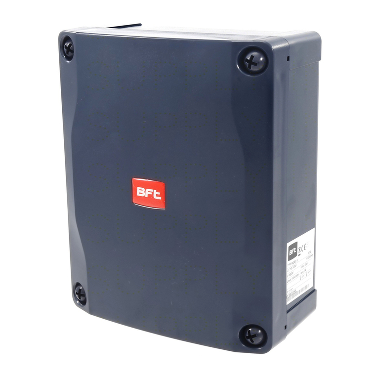
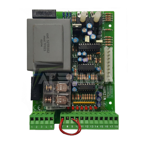
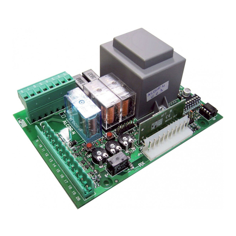
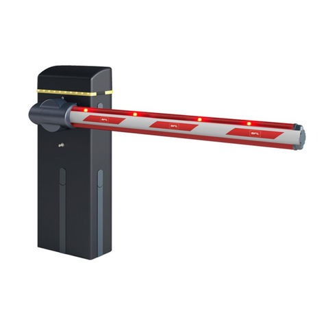
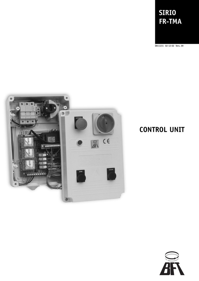
BFT SIRIO FR-TMA User manual

CENTRALINA DI COMANDO
CONTROL UNIT
UNITÉ DE COMMANDE
STEUERZENTRALE
CENTRAL DE MANDO
CENTRAL DO MANDO
D811231 ver. 13 26-09-07
I
GB
F
D
E
P
SIRIO FR-TMA / SIRIO TMA / SIRIO MA
Via Lago di Vico, 44
36015 Schio (VI)
Tel.naz. 0445 696511
Tel.int. +39 0445 696533
Fax 0445 696522
Internet: www.bft.it
E-mail: [email protected]
ISTRUZIONI D’USO E DI INSTALLAZIONE
INSTALLATION AND USER’S MANUAL
INSTRUCTIONS D’UTILISATION ET D’INSTALLATION
INSTALLATIONS-UND GEBRAUCHSANLEITUNG
INSTRUCCIONES DE USOY DE INSTALACION
INSTRUÇÕES DE USO E DE INSTALAÇÃO
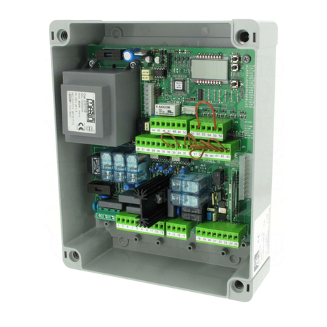
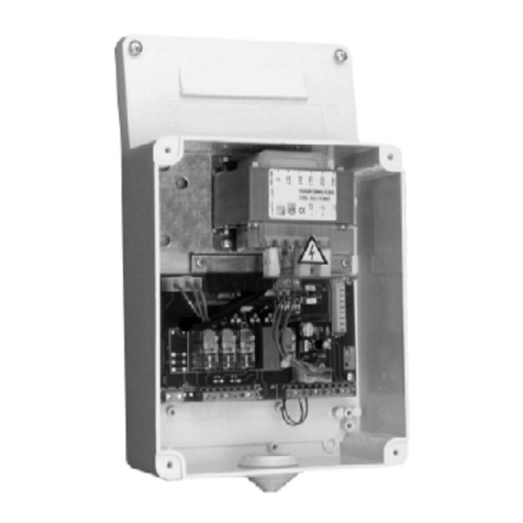
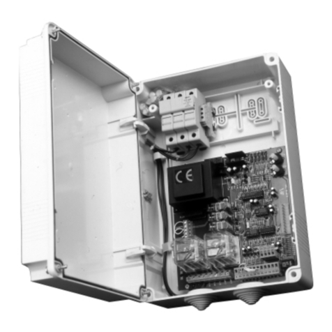
SIRIO FR-TMA SIRIO MASIRIO TMA
8027908 1 1 4 3 6 5

2 -SIRIO FR-TMA / SIRIO TMA / SIRIO MA - Ver. 13
D811231_13

SIRIO FR-TMA / SIRIO TMA / SIRIO MA - Ver. 13 - 3
D811231_13

USER’S MANUAL
ENGLISH
Thank you for buying this product, our company is sure that you will be more than satisfied with its performance. This product is supplied with an “In-
struction Manual” which should be read carefully as it provides important information about safety, installation, operation and maintenance.
This product complies with recognised technical standards and safety regulations.This product complies with the recognised technical standards and safety
regulations.We declare that this product is in conformity with the following European Directives: 89/336/EEC and 73/23/EEC, 98/37/CEE (and subsequent
amendments). with the following Technical Standards EN60335-1, PrEN12453 and PrEN12445.
WARNINGS
When carrying out wiring and installation work, always refer to current standards and good technical principles.
WARNINGS
Any assistance required on automation components must be carried out by a qualified technician (installer).
1) GENERAL OUTLINE (Fig.A)
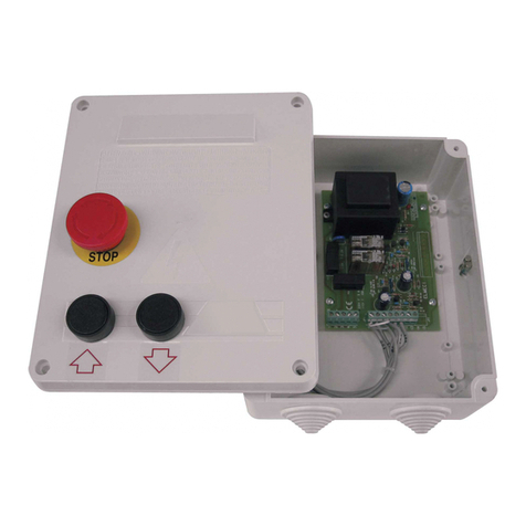
The control panel, equipped with a microprocessor control unit, is used to control a single-phase or three-phase operator fitted on a sliding gate or sectional
door for industrial use.
It is provided open/close/stop buttons (SIRIO FR TMA - SIRIO MA).
It is provided with a lockable switch and a warning light for anomalies (e.g. release activated, overstroke) (SIRIO FR TMA).
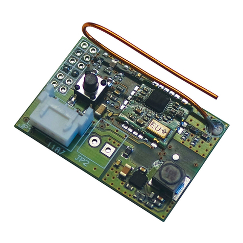
A series of LEDs allows to check or detect any operating anomalies in the control unit or on the connected devices. The control unit is supplied with
Dip-switches and Trimmers which provide configuration and calibration, respectively. Self-diagnosis: the control unit allows a check to be carried out
on operating relays and safety devices (photocells, rubber edge etc.) before any manoeuvre takes place.
2) MAINTENANCE AND DEMOLITION
The maintenance of the system should only be carried out by qualified personnel regularly. The materials making up the set and its packing must
be disposed of according to the regulations in force. Batteries must be properly disposed of.
MANUALE D’USO
ITALIANO
Nel ringraziarVi per la preferenza accordata a questo prodotto, la ditta è certa che da esso otterrete le prestazioni necessarie al Vostro uso. Leggete atten-
tamente l’opuscolo ”Libretto istruzioni” che lo accompagna in quanto esso fornisce importanti indicazioni riguardanti la sicurezza, l’installazione, l’uso e
la manutenzione. Questo prodotto risponde alle norme riconosciute della tecnica e delle disposizioni relative alla sicurezza.Confermiamo che è conforme
alle seguenti direttive europee: 89/336/CEE, 73/23/CEE, 98/37/CE (e loro modifiche successive), applicando le seguenti norme tecniche EN60335-1,
PrEN12453, PrEN12445.
AVVERTENZE
Nelle operazioni di cablaggio ed installazione riferirsi alle norme vigenti e comunque ai principi di buona tecnica.
AVVERTENZE
Qualunque intervento sui componenti dell’automazione deve essere eseguito da personale qualificato (installatore).
1) GENERALITÀ (Fig.A)
Il quadro, dotato di centralina a microprocessore, è adatto a controllare un attuatore monofase o trifase per cancello scorrevole oppure sezionale in am-
biente industriale.
Dispone di pulsanti di apre, chiude, stop (SIRIO FR TMA - SIRIO MA).
Dispone di interruttore lucchettabile e di luce spia di segnalazione anomalie (es.: sblocco attivo, intervento extracorsa) (SIRIO FR TMA).
Una serie di leds consente la verifica o l’individuazione di anomalie di funzionamento della centralina stessa o dei dispositivi collegati. La centralina è dotata
di Dip-switch e Trimmer che ne consentono la configurazione e la taratura. Autodiagnosi: la centralina consente di effettuare il controllo dei relè di marcia
e dei dispositivi di sicurezza (fotocellule, costa sensibile, ecc.), prima di eseguire ogni manovra.
2) MANUTENZIONE E DEMOLIZIONE
La manutenzione dell’impianto va fatta eseguire regolarmente da parte di personale qualificato. I materiali costituenti l’apparecchiatura e il suo
imballo vanno smaltiti secondo le norme vigenti. Le pile non devono essere disperse nell’ambiente.
MANUEL D’UTILISATION
FRANÇAIS
Nous vous félicitons pour avoir choisi ce produit. Nous sommes sûrs qu’il vous rendra le service nécessaire à vos besoins. Lisez attentivement le “Manuel
d’instructions” qui accompagne ce produit, puisqu’il fournit d’importantes indications concernant la sécurité, l’installation, l’utilisation et l’entretien. Ce
produit est conforme aux règles reconnues de la technique et aux dispositions de sécurité. Nous certifions sa conformité avec les directives européennes
suivantes: 89/336/CEE, 73/23/CEE, 98/37/CEE (et modifications successives), en appliquant les règles techniques suivantes EN60335-1, PrEN12453,
PrEN12445.
NOTICE
Pour les opérations de câblage et d’installation, se référer aux normes en vigueur et aux principes de bonne technique.
NOTICE
Toutes les interventions sur les composants de la motorisation doivent être effectuées par du personnel qualifié (installateur).
1) GÉNÉRALITÉS (Fig.A)
L’armoire de commande, dotée d’une unité de commande à microprocesseur, peut contrôler un opérateur monophasé ou triphasé pour portail coulissant
ou multilames pour le domaine industriel.
Elle dispose des touches ouvre, ferme, stop (SIRIO FR TMA - SIRIO MA)..
Elle dispose d’un interrupteur à cadenas et d’un témoin lumineux de signalisation des anomalies (ex. déblocage actif, intervention extracourse) (SIRIO FRTMA).
Une série de leds permet de vérifier ou de localiser les anomalies de fonctionnement de l’unité de commande ou des dispositifs annexes. L’unité de com-
mande est dotée d’interrupteurs dip et de trimmers qui en permettent la configuration et le réglage. Autodiagnostic: l’unité de commande permet d’effectuer
le contrôle des relais de marche et des dispositifs de sécurité (cellules photoélectriques, barre palpeuse, etc.), avant d’effectuer chaque manoeuvre.
2) ENTRETIEN ET DEMOLITION
L’entretien de l’installation doit être effectué régulièrement de la part de personnel qualifié. Les matériaux constituant l’appareillage et son emballage
doivent être mis au rebut conformément aux normes en vigueur. Les piles constituent des déchets spéciaux.
4 -SIRIO FR-TMA / SIRIO TMA / SIRIO MA - Ver. 13
D811231_13

SIRIO FR-TMA / SIRIO TMA / SIRIO MA - Ver. 13 - 5
D811231_13
Fig. A
SSBB1
Cavallotto di messa a terra
U-link for earth connection
Crampillon de mise à la terre
Erdanschlussklemmen
Perno de U de toma de tierra
Cabo descarnado de ligação à terra
Disponibilità di raccordi tubo - cassetta:
CRTR (raccordo con tubo rigido).
CRTL (raccordo con guaina flessibile).
Available couplings connecting the pipes to the box:
CRTR (coupling with rigid pipe).
CRTL (coupling with flexible sheath).
Disponibilité de raccords tube - boîte:
CRTR (raccord avec tube rigide).
CRTL (raccord avec tuyau souple).
Erhältliche Rohrverschraubungen für
Steuerungsgehäuse:
CRTR (Verbindungsstück für starres Rohr).
CRTL (Verbindungsstück für flexibles Rohr).
Disponibilidad de uniones tubo - caja:
CRTR (unión con tubo rígido).
CRTL (unión con vaina flexible).
Disponibilidade de conectores tubo - caixa:
CRTR (conector com tubo rígido).
CRTL (conector com bainha flexível).
Gruppo fusibili
Fuse set
Groupe fusibles
Sicherungsgruppe
Grupo fusibles
Grupo fusíveis
SSBB1
SIRIOTMA
SSBB1
Gruppo fusibili
Fuse set
Groupe fusibles
Sicherungsgruppe
Grupo fusibles
Grupo fusíveis
SIRIO FR-TMA
SIRIO TMA
SIRIO MA
Single earth pole for DIN bar connection
Pôle individuel de mise à la terre pour fixation de la barre DIN
Einzelner Erdungspol für den Anschluss an die Schranke DIN
Polo sencillo de tierra para la fijación de la barra din
Pólo singular de ligação de terra para conexão da barra DIN
SIRIOTMA
Sezionatore
Knife switch
Disjoncteur
Trennschalter
Interruptor
Seccionador

BEDIENUNGSANLEITUNG
DEUTSCH
Wir danken Ihnen, daß Sie sich für diese Anlage entschieden haben. Ganzsicher werden die Leistungen Ihren Ansprüchen vollauf gerecht werden.
Lesen Sie aufmerksam die Broschüre mit den “Gebrauchsanweisungen”, die dem Produkt beiliegen. Sie enthält wichtige Hinweise zur Sicherheit, Instal-
lation, Bedienung und Wartung der Anlage. Dieses Produkt genügt den anerkannten technischen Normen und Sicher-heitsbestimmungen.Wir bestätigen,
daß es mit folgenden Europäischen Richtlinien übereinstimmt:89/336/EWG, 73/23/EWG, 98/37/EWG (und ihren nachfolgende Änderungen), Als technische
Normen wurden angewendet: EN60335-1, PrEN12453, PrEN12445.
HINWEIS
Die Verkabelung und Installation sind nach den geltenden Vorschriften und fachgerecht durchzuführen.
HINWEIS
Alle Arbeiten an Bauteilen der Anlage sind von Fachleuten (Montagepersonal) durchzuführen.
1) ALLGEMEINES (Fig.A)
Die Bedientafel mit Mikroprozessorsteuerung ist für die Kontrolle eines ein oder dreiphasigen Antriebs für Schiebe- oder Sektionaltore im Industriebereich
geeignet.
Sie verfügt über Taster für Öffnung, Schließung und Stop (SIRIO FR TMA - SIRIO MA).
Sie verfügt über einen abschließbaren Schalter und eine Kontrollampe zur Anzeige von Fehlfunktionen (Bsp.: Entsperrung aktiviert, Endschalter ausgelöst)
(SIRIO FR TMA).
Durch eine Reihe von Leuchtdioden lassen sich Betriebsstörungen an der Steuerung oder den angeschlossenen Vorrichtungen kontrollieren und identifizieren.
Die Anlage verfügt über Dip -Schalter und Trimmer zur Konfiguration und Justierung. Selbstdiagnose: Die Steuerung kontrolliert vor jedem Arbeitsgang die
Relais für den Betriebsvorgang und die Sicherheitsvorrichtungen (Photozellen, Sicherheitsleiste etc).
2) INSTANDHALTUNG UND VERSCHROTTUNG
Die Anlagenwartung ist regelmäßig von Fachleuten vorzunehmen. Die Materialien, aus denen die Apparatur besteht und ihre Verpackung sind vor-
schriftsmäßig zu entsorgen. Die Batterien dürfen nicht in die Umwelt gelangen.
MANUAL DE USO
ESPAÑOL
Al agradecerle la preferencia que ha manifestado por este producto, la empresa está segura de que de él obtendrá las prestaciones necesarias para sus
exigencias. Lea atentamente el folleto “Manual de instrucciones” que lo acompaña, pues proporciona importantes indicaciones referentes a la seguridad,
la instalación, el uso y el mantenimiento. Este producto cumple los requisitos establecidos por las normas reconocidas de la técnica y las disposiciones
relativas a la seguridad. Confirmamos su conformidad con las siguientes directivas europeas: 89/336/CEE, 73/23/CEE, 98/37/CEE (y modificaciones
sucesivas), aplicando las siguientes normas técnicas: EN60335-1, PrEN12453,PrEN12445.
ADVERTENCIAS
En las operaciones de cableado e instalación, deben observarse las normas vigentes y, en cualquier caso, los principios de buena técnica.
ADVERTENCIAS
Cualquier intervención en los componentes del automatismo debe ser realizada por personal cualificado (instalador).
1) GENERALIDADES (Fig.A)
El cuadro, dotado de central de mando con microprocesador, está pensado para controlar un servomotor monofásico o trifásico para cancela corredera
o seccional de uso industrial.
Dispone de de botones de abre, cierra y stop (SIRIO FR TMA - SIRIO MA).
Dispone de interruptor que puede cerrarse con candado y de luz indicadora de anomalías (ej.: dispositivo de desbloqueo activado, intervención de carrera
extra) (SIRIO FR TMA).
Una serie de leds permite verificar o identificar eventuales anomalías en el funcionamiento de la central misma o de los dispositivos conectados. La central
está dotada de Dip-switches y Trimmers, que permiten su configuración y calibrado.
Autodiagnosis: la central permite efectuar el control de los relés de marcha y de los dispositivos de seguridad (fotocélulas, barra sensible, etc.), antes de
efectuar cualquier maniobra.
2) MANTENIMIENTO Y DEMOLICION
El mantenimiento de la instalación debe ser realizado, con regularidad, por personal cualificado. Los materiales que constituyen el equipo y su
embalaje deben eliminarse de conformidad con las normas vigentes.
Las pilas deben depositarse en los contenedores expresamente previstos.
MANUAL PARA DE USO
PORTUGUÊS
Agradecendolhe pela preferência dada a este produto, a Empresa tem a certeza que do mesmo obterá as prestações necessárias para o uso que entende
fazer. Leia atentamente o opúsculo ”Manual de instruções” que o acompanha, pois que esse fornece indicações importantes respeitantes a segurança,
a instalação, o uso e a manutenção. Este produto está em conformidade com as normas reconhecidas pela técnica e pelas disposições relativas à se-
gurança Confirmamos que o mesmo está em conformidade com as seguintes directivas europeias: 89/336/CEE, 73/23/CEE, 98/37/CEE (e modificações
sucessivas), aplicando as seguintes normas técnicas EN60335-1, PrEN12453, PrEN12445.
RECOMENDAÇÕES
Nas operações de cablagem e instalação faça referência às normas legais e técnicas vigentes e de todas as formas, aos códigos de uma boa prática.
RECOMENDAÇÕES
Toda e qualquer intervenção efectuada nos componentes da automatização deve ser levada a cabo por pessoal qualificado (instalador).
1) GENERALIDADES (Fig.A)
O quadro, dotado de central com microprocessador, é apropriado para controlar um accionador monofásico ou trifásico para portão de correr ou seccional
em ambientes industriais.
Equipado de botões de abre, fecha, stop (SIRIO FR TMA - SIRIO MA).
Equipado de interruptor que pode ser fechado a cadeado e de indicador luminoso de sinalização das anomalias (ex.: desbloqueio activo, intervenção
extracurso) (SIRIO FR TMA).
Uma série de leds consente de efectuar a verificação ou detecção de anomalias de funcionamento da central ou dos dispositivos ligados. A central está
equipada de Dip-switch eTrimmer que consentem de efectuar respectivamente, a configuração e a regulação. Auto-diagnóstico: antes de efectuar qualquer
manobra, a central efectua o controlo dos relés de marcha e dos dispositivos de segurança (fotocélulas, perfis sensíveis, etc.).
2) MANUTENÇÃO E DEMOLIÇÃO
A manutenção da instalação deve ser executada periodicamente por pessoal qualificado. Os materiais que constituem a aparelhagem e a sua
embalagem devem ser eliminados de acordo com a legislação vigente. As pilhas não devem ser abandonadas no ambiente.
6 -SIRIO FR-TMA / SIRIO TMA / SIRIO MA - Ver. 13
D811231_13

SIRIO FR-TMA / SIRIO TMA / SIRIO MA - Ver. 13 - 7
D811231_13
Fig. A
SSBB1
Cavallotto di messa a terra
U-link for earth connection
Crampillon de mise à la terre
Erdanschlussklemmen
Perno de U de toma de tierra
Cabo descarnado de ligação à terra
Disponibilità di raccordi tubo - cassetta:
CRTR (raccordo con tubo rigido).
CRTL (raccordo con guaina flessibile).
Available couplings connecting the pipes to the box:
CRTR (coupling with rigid pipe).
CRTL (coupling with flexible sheath).
Disponibilité de raccords tube - boîte:
CRTR (raccord avec tube rigide).
CRTL (raccord avec tuyau souple).
Erhältliche Rohrverschraubungen für
Steuerungsgehäuse:
CRTR (Verbindungsstück für starres Rohr).
CRTL (Verbindungsstück für flexibles Rohr).
Disponibilidad de uniones tubo - caja:
CRTR (unión con tubo rígido).
CRTL (unión con vaina flexible).
Disponibilidade de conectores tubo - caixa:
CRTR (conector com tubo rígido).
CRTL (conector com bainha flexível).
Disponibilità di raccordi tubo - cassetta:
CRTR (raccordo con tubo rigido).
CRTL (raccordo con guaina flessibile).
Available couplings connecting the pipes to the box:
CRTR (coupling with rigid pipe).
CRTL (coupling with flexible sheath).
Disponibilité de raccords tube - boîte:
CRTR (raccord avec tube rigide).
CRTL (raccord avec tuyau souple).
Erhältliche Rohrverschraubungen für
Steuerungsgehäuse:
CRTR (Verbindungsstück für starres Rohr).
CRTL (Verbindungsstück für flexibles Rohr).
Disponibilidad de uniones tubo - caja:
CRTR (unión con tubo rígido).
CRTL (unión con vaina flexible).
Disponibilidade de conectores tubo - caixa:
CRTR (conector com tubo rígido).
CRTL (conector com bainha flexível).
Gruppo fusibili
Fuse set
Groupe fusibles
Sicherungsgruppe
Grupo fusibles
Grupo fusíveis
SSBB1
SIRIOTMA
SSBB1
Gruppo fusibili
Fuse set
Groupe fusibles
Sicherungsgruppe
Grupo fusibles
Grupo fusíveis
SIRIO FR-TMA
SIRIO TMA
SIRIO MA
Single earth pole for DIN bar connection
Pôle individuel de mise à la terre pour fixation de la barre DIN
Einzelner Erdungspol für den Anschluss an die Schranke DIN
Polo sencillo de tierra para la fijación de la barra din
Pólo singular de ligação de terra para conexão da barra DIN
SIRIOTMA
Sezionatore
Knife switch
Disjoncteur
Trennschalter
Interruptor
Seccionador

MANUALE PER L’INSTALLAZIONE
ITALIANO
Nel ringraziarVi per la preferenza accordata a questo prodotto, la Ditta è
certa che da esso otterrete le prestazioni necessarie al Vostro uso. Leggete
attentamente l’opuscolo ”Libretto istruzioni” che lo accompagna in quanto
esso fornisce importanti indicazioni riguardanti la sicurezza, l’installazione,
l’uso e la manutenzione. Questo prodotto risponde alle norme riconosciute
della tecnica e delle disposizioni relative alla sicurezza.Confermiamo che è
conforme alle seguenti direttive europee: 89/336/CEE, 73/23/CEE, 98/37/
CE (e loro modifiche successive), applicando le seguenti norme tecniche
EN60335-1, PrEN12453, PrEN12445.
AVVERTENZE
Nelle operazioni di cablaggio ed installazione riferirsi alle norme vigenti e
comunque ai principi di buona tecnica.
AVVERTENZE
Qualunque interventosui componentidell’automazionedeveessereeseguito
da personale qualificato (installatore).
1) GENERALITÀ
Il quadro, dotato di centralina a microprocessore, è adatta a controllare un
attuatore monofase o trifase per cancello scorrevole oppure sezionale in
ambiente industriale.
Dispone di pulsanti di apre, chiude, stop (SIRIO FR TMA - SIRIO MA).
Dispone di interruttore lucchettabile e di luce spia di segnalazione anomalie
(es.: sblocco attivo, intervento extracorsa) (SIRIO FR TMA).
Una serie di leds consente la verifica o l’individuazione di anomalie di fun-
zionamento della centralina stessa o dei dispositivi collegati. La centralina
è dotata di Dip-switch e Trimmer che ne consentono la configurazione e la
taratura.Autodiagnosi: la centralina consente di effettuare il controllo dei relè
di marcia e dei dispositivi di sicurezza (fotocellule, costa sensibile, ecc.),
prima di eseguire ogni manovra.
2) SICUREZZA GENERALE
ATTENZIONE! Una installazione errata o un uso improprio del prodotto,
può creare danni a persone, animali o cose.
• Leggete attentamente l’opuscolo ”Avvertenze” ed il ”Libretto istruzioni”
che accompagnano questo prodotto, in quanto forniscono importanti indi-
cazioni riguardanti la sicurezza, l’installazione, l’uso e la manutenzione.
• Smaltire i materiali di imballo (plastica, cartone, polistirolo, ecc.) secondo
quantoprevisto dallenormevigenti.Nonlasciarebustedinylone polistirolo
a portata dei bambini.
• Conservare le istruzioni per allegarle al fascicolo tecnico e per consulta-
zioni future.
• Questoprodotto è statoprogettato ecostruitoesclusivamente perl’utilizzo
indicato in questa documentazione. Usi non indicati in questa documen-
tazione potrebbero essere fonte di danni al prodotto e fonte di pericolo.
• LaDittadeclinaqualsiasiresponsabilitàderivantedall’usoimproprioodiverso
da quello per cui è destinato ed indicato nella presente documentazione.
• Non installare il prodotto in atmosfera esplosiva.
• La Ditta declina qualsiasi responsabilità dall’inosservanza della Buona
Tecnica nella costruzione delle chiusure (porte, cancelli, ecc.), nonché
dalle deformazioni che potrebbero verificarsi durante l’uso.
• L’installazione deve essere in accordo con quanto previsto dalle Direttive Eu-
ropee: 89/336/CEE, 73/23/CEE, 98/37/CEE e loro modifiche successive.
• Toglierel’alimentazioneelettrica,primadiqualsiasiinterventosull’impianto.
Scollegare anche eventuali batterie tampone se presenti.
• Prevedere sulla rete di alimentazione dell’automazione, un interruttore
o un magnetotermico onnipolare con distanza di apertura dei contatti
uguale o superiore a 3,5 mm.
• Verificare che a monte della rete di alimentazione, vi sia un interruttore
differenziale con soglia da 0.03A.
•Per la versione SIRIO MA l’alimentazione del quadro deve essere protetta
da 3 fusibili con valore massimo di 4A/400 V~. I fusibili vanno scelti in
modo che intervangono in caso di bloccaggio del motore.
• Verificare se l’impianto di terra è realizzato correttamente: collegare tutte
le parti metalliche della chiusura (porte, cancelli, ecc.) e tutti i componenti
dell’impianto provvisti di morsetto di terra.
• La Ditta declina ogni responsabilità ai fini della sicurezza e del buon
funzionamento dell’automazione se vengono impiegati componenti di
altri produttori.
• Usare esclusivamente parti originali per qualsiasi manutenzione o ripa-
razione.
• Non eseguire alcuna modifica ai componenti dell’automazione se non
espressamente autorizzata dalla Ditta.
• Istruire l’utilizzatoredell’impianto per quantoriguardai sistemidicomando
applicati e l’esecuzione dell’apertura manuale in caso di emergenza.
• Non permettere a persone e bambini di sostare nell’area d’azione del-
l’automazione.
• Non lasciare radiocomandi o altri dispositivi di comando alla portata dei
bambini onde evitare azionamenti involontari dell’automazione.
• L’utilizzatore deve evitare qualsiasi tentativo di intervento o riparazione
dell’automazione e rivolgersi solo a personale qualificato.
• Tutto quello che non è espressamente previsto in queste istruzioni, non
è permesso.
• L’installazione deve essere fatta utilizzando dispositivi di sicurezza e
comandi conformi alla EN 12978.
3) DATI TECNICI
Alimentazione (*): ...................................trifase 400V~ ; monofase 230V~
Corrente uscita motore: ........................................... 2A/400V~; 4A/230V~
Corrente commutaz.motori: .................................. 8A/400V~ ; 12A/230V~
Isolamento rete - bassa tensione: ................................. > 2MOhm 500V
Rigidità dielettrica rete/bt: ........................................................... 3750V~1’
Potenza massima motore: ......................................................750W: 375W
Alimentazione accessori: ........................................ 24V~/0.5A: 24V~/0.5A
Spia cancello aperto: .......................................................24V/3W: 24V/3W
Lampeggiatore: ........................................................230V/40W: 230V/40W
Fusibili: .......................................................................................... vedi fig.1
Dimensioni: .................................................................................vedi fig.1A
(*)(altre tensioni a richiesta)
4) COLLEGAMENTI (Fig.3)
AVVERTENZE - Nelle operazioni di cablaggio ed installazione riferirsi alle
norme vigenti e comunque ai principi di buona tecnica.
I conduttori alimentati con tensioni diverse, devono essere fisicamente
separati, oppure devono essere adeguatamente isolati con isolamento
supplementare di almeno 1mm.
I conduttori devono essere vincolati da un fissaggio supplementare in pros-
simità dei morsetti, per esempio mediante fascette.
ATTENZIONE! Per il collegamento alla rete, utilizzare cavo multipolare
di sezione minima 3x1.5mm2e del tipo previsto dalle normative vigenti.
A titolo di esempio, se il cavo è all’esterno (all’aperto), deve essere
almeno pari a H07RN-F mentre, se all’interno (in canaletta),deve essere
almeno pari a H05 VV-F con sezione 3x1.5mm2.
N.B.:Prima di collegare la centralina alla rete, controllare che il morsetto JP5
(cambio tensione), sia predisposto per la giusta tensione di lavoro.
Laschedavienefornitaconunaserie dimorsetti ponticellati.Ipontiriguardano
i morsetti: 26-29, 26-30, 26-31, 26-35. Se questi morsetti non
vengano utilizzati, lasciarli ponticellati. Nella morsettiera ausiliaria SSBB1,
sono ponticellati i morsetti 6-7, 8-9, 10-11. Nel caso questi morsetti non
vengano utilizzati, lasciarli ponticellati.
QUADRO
Importante: L’alimentazione del quadro, va collegata ai morsetti del sezio-
natore “S” (SIRIO FR TMA).
S - TRIFASE
R-S-T-N ...............................................Trifase 400V ±10% 50Hz + Neutro.
ATTENZIONE! (cambio tensione JP5/39-40).
S - MONOFASE
R-N ................................................................Monofase 230V ±10% 50Hz.
ATTENZIONE! (cambio tensione JP5/40-41).
CENTRALINA
JP1 - TRIFASE
1-2-3-4 Alimentazione trifase+neutro 400V.
(1 Neutro, 2-3-4 fase)(N.B.: ponte di JP5 tra 39-40).
5-6-7 Collegamento motore trifase.
8-9 Uscita 230V~per luce lampeggiante.
JP1 MONOFASE
1-2 Alimentazione monofase 230V.
(1 Neutro, 2 fase) (N.B.: ponte di JP5 tra 40-41).
5-6-7 Collegamentomotoremonofase(5-7marciamotoreecondensatore,
6 comune).
8-9 Uscita 230V~per luce lampeggiante.
JP2
10-11 Uscita 24V~(3W) per luce spia di segnalazione sblocco motore e/o
porta pedonale. La spia si accende a motore sbloccato (manovra
manuale) o a porta pedonale aperta.
11-12 Alimentazione accessori 24V~ e ricevitori dispositivi di sicurezza
non sottoposti a verifica.
12-13 Alimentazione 24VTx solo per trasmettitori dispositivi di sicurezza
sottoposti a verifica.
14 Ingresso LOOP1 dell’anello di verifica sicurezze (vedere fig.5).
15 Ingresso LOOP2 dell’anello di verifica sicurezze (vedere fig.5).
16-17 Uscita secondo canale radio scheda ricevente bicanale (n.o.).
18-19 Ingresso antenna scheda radioricevente (18 segnale, 19 calza).
8 -SIRIO FR-TMA / SIRIO TMA / SIRIO MA - Ver. 13
D811231_13

MANUALE PER L’INSTALLAZIONE ITALIANO
JP7
20-21-22
23-24-25 Ingressi per il collegamento dei dispositivi di sicurezza da verificare
(vedere fig.5).
JP4
26-27 Pulsante START (n.o.).
26-28 Pulsantediblocco(n.c.).Ulteriori pulsantidevono esserecollegatiin
serie tra loro.
26-29 Ingresso contatto fotocellula (n.c.). Se non si utilizza lasciare
inserito. Se si utilizza in verifica osservare cablaggio di fig.5.
26-30 Finecorsa di apertura (n.c.). Se non utilizzato lasciare ponticella-
to.
26-31 Finecorsa di chiusura (n.c.). Se non utilizzato lasciare ponticella-
to.
26-32 Pulsante pedonale (n.o.).
26-33 Pulsante Apre (n.o.).
26-34 Pulsante Chiude (n.o.).
26-35 Ingresso contatto costa IR (n.c.). Se non si utilizza lasciare ponti-
cellato.
26-36 Ingresso micro Passo Uomo (controllo porta pedonale).
JP5
37-38 ATTENZIONE! Tensione di rete ai morsetti.
Collegamento pulsante di emergenza (n.c.).
Utilizzare un pulsante a ritenuta con due contatti n.c. con almeno
8mm di distanza tra i due contatti. Se non si utilizza lasciare pon-
ticellato.
39-40 Cambio tensione a 400V~trifase.
40-41 Cambio tensione a 230V~monofase.
JP6
Connettore scheda radioricevente 1-2 canali.
MORSETTIERA SSBB1
1 Collegato al morsetto 26 della scheda di comando.
2-3-4 Collegamenti comuni ausiliari.
4-5 Stop.
6-7 Contatto N.C.micro porticina pedonale. Se non utilizzato, lasciare
ponticellato.
8-9 Contatto (N.C.) rottura MOLLA 1. Se non utilizzato, lasciare pon-
ticellato.
10-11 Contatto (N.C.) rottura MOLLA 2. Se non utilizzato, lasciare pon-
ticellato.
12 Collegato al morsetto 28 della scheda di comando.
5) COLLEGAMENTO DISPOSITIVI DI SICUREZZA
• Per i dispositivi standard a 4 morsetti, privi di autodiagnostica, è possibile
la connessione senza verifica come indicato al punto 5.1.
• Per la connessione di dispositivi dotati di autodiagnostica interna fate
riferimento al punto 5.2.
• Idispositivi standard a5 morsetti,prividi autodiagnostica,possonoessere
inseriti nel ciclo di controllo ed autodiagnostica, seguendo le indicazioni
del punto 5.3.
5.1) Dispositivi di sicurezza SENZA AUTODIAGNOSI
Eseguirei collegamenti comerappresentatoinfig.4.Mantenerei Dip-switch 9
e 10 in ON (settaggio fornito di serie). I contatti di intervento di più dispositivi
uguali, devono essere collegati in serie tra loro.
5.2) Dispositivi di sicurezza CON AUTODIAGNOSI INTERNA
Eseguirei collegamenti comerappresentatoinfig.4.Mantenerei Dip-switch 9
e 10 in ON (settaggio fornito di serie). I contatti di intervento di più dispositivi
uguali, devono essere collegati in serie tra loro.
5.3) Dispositivi di sicurezza SENZA AUTODIAGNOSI ma DOTATI DI
CONTATTI IN SCAMBIO LIBERI DA TENSIONE.
Per convenzione si fa riferimento ad un dispositivo ricevente (Rx- fig.5) a 5
morsetti dei quali: morsetti 1 e 2 di alimentazione 24Vac, morsetto 3 comu-
ne, morsetto 4 contatto normalmente chiuso a riposo, morsetto 5 contatto
normalmente aperto a riposo.
A) In fig.5 “A”, è rappresentato il collegamento per l’alimentazione delle
riceventi e delle trasmittenti di cui si vuole eseguire l’autodiagnosi.
B) Fig. 5 “B”. Collegamento di una o più riceventi (fotocellule) uguali fino ad
un massimo di quattro (Dip 9 OFF/Dip 10 ON, solo fotocellule, lasciare
ponticellato 35-26).
Ad esempio, con due fotocellule, collegare F1 ed F2, poi spezzare la
catena del collegamento collegando il morsetto 4 di F2 a LOOP1 ed il
morsetto 5 di F2 a COM. Se la ricevente da collegare è una, eseguire il
collegamento rappresentato in fig.5 rif.1.Se le riceventi da collegare sono
meno di quattro, occorre spezzare la catena del collegamento eseguendo
i collegamenti rappresentati in fig.5 rif.2 o 3.
Se i dispositivi sono esclusivamente coste sensibili anzichè fotocellule,
utilizzare il morsetto 35-BAR della centralina (Dip 9 ON/Dip 10 OFF,
lasciare ponticellato 29-26).
C) Collegamento di una fotocellula ed una costa.(Dip 9 OFF/Dip 10 OFF)
D) Collegamento di due fotocellule e una costa.(Dip 9 OFF/Dip 10 OFF)
Nel caso si colleghino due coste e una fotocellula, F1 ed F2 di fig.5 “D”
diventano 2 coste, e C1 una fotocellula; invertire tra loro i collegamenti
PHOT e BAR della centralina.(Dip 9 OFF/Dip 10 OFF)
E) Collegamento di tre fotocellule e una costa.(Dip 9 OFF/Dip 10 OFF)
Nel caso si colleghino tre coste e una fotocellula, F1, F2 ed F3 (fig.5 “E”)
diventano 3 coste e C1 una fotocellula; invertire tra loro i collegamenti
PHOT e BAR della centralina.(Dip 9 OFF/Dip 10 OFF)
F) Collegamento di tre fotocellule e due coste. Nel caso si colleghino tre
coste e due fotocellule, F1, F2 ed F3 (fig.5 “F”) diventano tre coste, C1
e C2 due fotocellule; invertire tra loro i collegamenti PHOT e BAR della
centralina.(Dip 9 OFF/Dip 10 OFF)
G) Collegamento di quattro fotocellule e una costa. Nel caso si colleghino
quattro coste e una fotocellula, F1, F2 , F3 ed F4 (fig.5 “G”) diventano
quattro coste e C1 una fotocellula; invertire tra loro i collegamenti PHOT
e BAR della centralina.(Dip 9 OFF/Dip 10 OFF)
6) LOGICA DI FUNZIONAMENTO
6.1) Dip-switch
Dip 1 e 2 ........................................................................Fotocellule (FCH)
ON - Esclude il funzionamento della fotocellula in apertura ed inverte imme-
diatamente in fase di chiusura in caso di oscuramento della fotocellula.
OFF - Se un ostacolo oscura la fotocellula quando il cancello sta chiudendo
si ottiene l’arresto dello stesso; una volta liberato l’ostacolo il cancello si
riapre. Se un ostacolo oscura la fotocellula quando il cancello si sta apren-
do si ottiene l’arresto dello stesso; una volta liberato l’ostacolo il cancello
continua l’apertura.
Dip 3 .........................................................................Blocca impulsi (IBL)
ON - L’impulso di start / start pedonale non ha alcun effetto in fase di
apertura.
OFF - L’impulso di start / start pedonale durante la fase di apertura provoca
l’arresto del cancello.
Dip 4 ............................................................. Chiusura automatica (TCA)
ON - Esegue la chiusura automatica del cancello dopo un tempo di pausa
impostato dal trimmer TCA.
La chiusura automatica viene attivata dall’arrivo del cancello in posizione
di finecorsa apertura, dalla fine del tempo di lavoro in fase di apertura o
dall’arresto del cancello in fase di apertura mediante impulso di start.
OFF - Esclude la chiusura automatica.
Dip 5 ............................................................ Logica a 2 o 4 passi (2P/4P)
ON - Un impulso di start dato mentre il cancello è in chiusura provoca l’inver-
sione del senso di marcia, in apertura provoca l’arresto (Dip 3 in OFF).
OFF - Un impulso di start dato mentre il cancello è in movimento provoca
l’arresto; il successivo impulso provoca l’inversione del senso di marcia
(logica 4 passi).
N.B.: L’impulso di start in fase di apertura non ha comunque effetto con
Dip 3 in ON.
Dip 6 ....................................................................... Preallarme (PREALL)
ON - Il lampeggiante si accende circa 3 secondi prima della partenza del
motore.
OFF - Il lampeggiante si accende contemporaneamente alla partenza del
motore.
Dip 7........................................................... Comando Apre/Chiude (U.P.)
Agisce sui segnali collegati ai morsetti 33-34.
ON - Funzionamento a uomo presente: la manovra continua finchè viene
mantenuta la pressione sul tasto di comando.
OFF - Funzionamento Apre/Chiude separato automatico: con un impulso
apre il cancello se chiuso e viceversa.
Dip 8 .......................Scala dei tempi di lavoro ridotta o normale (S.TW)
ON - Tempo di lavoro TW compreso nell’intervallo 1-90 secondi (tempo di
lavoro pedonale TW.PED da 1 a 20 secondi).
OFF - Tempo di lavoro TW compreso nell’intervallo 3 ÷ 210 secondi (tempo
di lavoro pedonale TW.PED da 5 a 60 secondi).
Dip 9..................................................... Fotocellule non verificate (FNV)
Agisce sulla logica di controllo delle fotocellule.
ON - Le fotocellule sono escluse dal ciclo di verifica sicurezze effettuato
prima di ogni manovra; ne viene comunque analizzato lo stato logico (ri-
ferirsi come collegamento al tipico modo di collegare le fotocellule ovvero
con fascio sempre attivo). Utilizzato per collegare fotocellule non verificate
oppure con autodiagnosi interna e che comunque forniscono in uscita un
contatto libero da tensione.
OFF - Le fotocellule vengono inserite nel ciclo di verifica sicurezze Ok
effettuato prima di ogni manovra.
Per il collegamento riferirsi agli schemi allegati.
SIRIO FR-TMA / SIRIO TMA / SIRIO MA - Ver. 13 - 9
D811231_13

MANUALE PER L’INSTALLAZIONE
ITALIANO
Dip 10 ............................................................Costa non verificata (BAR)
Agisce sulla logica di controllo del dispositivo costa sensibile.
ON - I dispositivi costa sono esclusi dal ciclo di verifica sicurezze effettuato
prima di ogni manovra;ne viene comunque analizzato lo stato logico (riferirsi
come collegamento al tipico modo di collegare le coste infrarossi, ovvero
con fascio sempre attivo). Utilizzato per collegare coste IR non verificate
oppure con autodiagnosi interna e che comunque forniscono in uscita un
contatto libero da tensione.
OFF - I dispositivi costa IR vengono inseriti nel ciclo di verifica sicurezze
Ok effettuato prima di ogni manovra. Per il collegamento riferirsi agli schemi
allegati.
6.2) Funzioni regolate dai Trimmer
TW.PED
Regola il tempo di lavoro parziale di uno scorrevole con doppia
funzione di passaggio veicolare e pedonale.
TW Regola il tempo di funzionamento sia in apertura che in chiusura
(regolabile da 3 a 210 secondi).
TCA Regola il tempo di pausa dopo il quale il cancello si richiudeauto-
maticamente (regolabile da 1 a 120 secondi).
6.3) Funzione dei LED
Una serie di leds consente la verifica o l’individuazione di anomalie di fun-
zionamento della centralina stessa o dei dispositivi collegati.
(DL1) Rimane acceso in presenza di rete e con fusibile F1 integro.
(DL2) Si accende quando il motore è attivato in chiusura.
(DL3) Si accende quando il motore è attivato in apertura.
(DL4) Si accende al comando di start o all’attivazione del primo canale
della ricevente radio.
(DL5) Si spegne al comando di blocco.
(DL6) Sispegne confotocellulenon allineateovvero inpresenza diostacoli.
Nella modalità Dip 9 in OFF le fotocellule e relativo led vengono
attivati solo durante la manovra.
(DL7) Si spegne con cancello in posizione di completa apertura, se dotato
di finecorsa.
(DL8) Si spegne con cancello in posizione di completa chiusura, se dotato
di finecorsa.
(DL9) Si accende al comando di start per cancello pedonale.
(DL10) Si accende con comando manuale di apertura.
(DL11) Si accende con comando manuale di chiusura.
(DL12) Si spegne quando interviene la costa pneumatica. Nella modalità
Dip 10 in OFF la costa e relativo led vengono attivati solo durante
la manovra.
(DL13) Si accende con anello sicurezze chiuso.
(DL14) Si accende con intervento micro di sicurezza.
7) MANUTENZIONE E DEMOLIZIONE
La manutenzione dell’impianto va fatta eseguire regolarmente da parte
di personale qualificato. I materiali costituenti l’apparecchiatura e il suo
imballo vanno smaltiti secondo le norme vigenti.Le pile non devono essere
disperse nell’ambiente.
Le descrizioni e le illustrazioni del presente manuale non sono impe-
gnative. Lasciando inalterate le caratteristiche essenziali del prodotto,
la Ditta si riserva di apportare in qualunque momento le modifiche che
essa ritiene convenienti per migliorare tecnicamente-costruttivamente
e commercialmente il prodotto, senza impegnarsi ad aggiornare la
presente pubblicazione.
10 -SIRIO FR-TMA / SIRIO TMA / SIRIO MA - Ver. 13
D811231_13

INSTALLATION MANUAL ENGLISH
Thank you for buying this product, our company is sure that you will be
more than satisfied with its performance. This product is supplied with an
“Instruction Manual”which should be read carefully as it provides important
information about safety, installation, operation and maintenance.
This product complies with recognised technical standards and safety
regulations.This product complies with the recognised technical standards
and safety regulations. We declare that this product is in conformity with the
following European Directives:89/336/EEC and 73/23/EEC, 98/37/CEE (and
subsequent amendments).with the followingTechnical Standards EN60335-
1, PrEN12453 and PrEN12445.
WARNINGS
When carrying out wiring and installation work, always refer to current stan-
dards and good technical principles.
WARNINGS
Any assistance required on automation components must be carried out by
a qualified technician (installer).
1) GENERAL OUTLINE
The control panel, equipped with a microprocessor control unit, is used to
control a single-phase or three-phase operator fitted on a sliding gate or
sectional door for industrial use.
It is provided open/close/stop buttons (SIRIO FR TMA - SIRIO MA).
It is provided with a lockable switch and a warning light for anomalies (e.g.
release activated, overstroke) (SIRIO FR TMA).
A series of LEDs allows to check or detect any operating anomalies in the
control unit or on the connected devices. The control unit is supplied with
Dip-switches and Trimmers which provide configuration and calibration,
respectively. Self-diagnosis: the control unit allows a check to be carried out
on operating relays and safety devices (photocells, rubber edge etc.) before
any manoeuvre takes place.
2) GENERAL SAFETY
WARNING! An incorrect installation or improper use of the product can
cause damage to persons, animals or things.
• The “Warnings” leaflet and “Instruction booklet” supplied with this
product should be read carefully as they provide important information
about safety, installation, use and maintenance.
• Scrap packing materials (plastic, cardboard, polystyrene etc) according
to the provisions set out by current standards. Keep nylon or polystyrene
bags out of children’s reach.
• Keep the instructions together with the technical brochure for future
reference.
• This product was exclusively designed and manufactured for the use
specified in the present documentation. Any other use not specified in
this documentation could damage the product and be dangerous.
• The Company declines all responsibility for any consequences result-
ing from improper use of the product, or use which is different from that
expected and specified in the present documentation.
• Do not install the product in explosive atmosphere.
• The Company declines all responsibility for any consequences resulting
from failure to observe Good Technical Practice when constructing clos-
ing structures (door, gates etc.), as well as from any deformation which
might occur during use.
• The installation must comply with the provisions set out by the following
European Directives: 89/336/EEC, 73/23/EEC, 98/37/ECC and subse-
quent amendments.
• Disconnect the electrical power supply before carrying out any work on
the installation. Also disconnect any buffer batteries, if fitted.
• Fit an omnipolar or magnetothermal switch on the mains power supply,
having a contact opening distance equal to or greater than 3,5 mm.
• Check that a differential switch with a 0.03A threshold is fitted just before
the power supply mains.
• For the SIRIO MA version, the control panel power supply must be pro-
tected by 3 fuses having a maximum value of 4A/400 V~. Choose the
type of fuses which will be triggered in case of motor seizure.
• Check that earthing is carried out correctly: connect all metal parts for
closure (doors, gates etc.) and all system components provided with an
earth terminal.
•
TheCompanydeclinesallresponsibilitywithrespecttotheautomation safety
and correct operation when other manufacturers’ components are used.
• Only use original parts for any maintenance or repair operation.
• Do not modify the automation components, unless explicitly authorised
by the company.
• Instruct the product user about the control systems provided and the
manual opening operation in case of emergency.
• Do not allow persons or children to remain in the automation operation area.
• Keep radio control or other control devices out of children’s reach, in
order to avoid unintentional automation activation.
• The user must avoid any attempt to carry out work or repair on the automa-
tion system, and always request the assistance of qualified personnel.
• Anything which is not expressly provided for in the present instructions,
is not allowed.
• Installation must be carried out using the safety devices and controls
prescribed by the EN 12978 Standard.
3) TECHNICAL SPECIFICATIONS
Power supply (*):.........................400 V~ three-phase230 V~single-phase
Motor output current:................................................2A/400V~ ; 4A/230V~
Motor output comm. current:...................................8A/400V~ ; 12A/230V~
Mains - low voltage insulation:....................................... > 2MOhm 500V
Mains - low voltage dielectric strength:........................................3750V~1’
Maximum motor power: ...........................................................750W 375W
Power supply to accessories:....................................24V~/0,5A 24V~/0,5A
Gate-open warning light:......................................................24V/3W 24/3W
Blinker:...................................................................... 230V/40W 230V/40W
Fuses:.............................................................................................see fig.1
Dimensions:..................................................................................see fig.1A
(*) (other voltages on request)
4) CONNECTIONS (Fig.3)
WARNINGS - For wiring and installation operations, refer to the current
standards and good technical principles.
Wires powered at different voltages must be physically separated, or suitably
insulated with at least 1 mm extra insulation. The wires must be clamped by
an extra fastener near the terminals, for example by bands.
WARNING! For connection to the mains, use a multipolar cable with
a minimum of 3x1.5mm2cross section and complying with the previ-
ously mentioned regulations. For example, if the cable is out side (in
the open), it has to be at least equal to H07RN-F, but if it is on the inside
(or outside but placed in a plastic cable cannel) it has to be or at least
egual to H05VV-F with section 3x1.5mm2.
N.B.: Before connecting the control unit to the mains voltage, check that the
JP5 (voltage change) terminal is preset for the correct working voltage.
The board is supplied with a series of previously bridged terminals.
The jumpers refer to the following terminals: 26-29, 26-30, 26-31, 26-35. If
these terminals are not used, leave them bridged. In the additional terminal
board SSBB1, the terminals 6-7, 8-9 and 10-11 are bridged.
If these terminals are not used, leave them bridged.
PANEL
Caution: the panel power supply must be connected to the “S” breaker
(SIRIO FR TMA).
S - THREE- PHASE
R-S-T-N......................................Three-phase 400V ±10% 50Hz + Neutral.
CAUTION! (voltage change JP5/39-40).
S - SINGLE-PHASE
R-N............................................................Single-phase 230V ±10% 50Hz.
CAUTION! (voltage change JP5/40-41).
CONTROL UNIT
JP1 - THREE-PHASE
1-2-3-4 Three-phase power supply+neutral 400V.
(1 Neutral, 2-3-4 phase)(Note: JP5 jumper between 39-40).
5-6-7 Three-phase motor connection.
8-9 230V~output for blinker.
JP1 - SINGLE-PHASE
1-2 Single-phase power supply 230V.
(1 Neutral, 2 phase) (N.B.: JP5 jumper between 40-41).
5-6-7 Single-phasemotorconnection(5-7motorand capacitoroperation,
6 common terminal).
8-9 230V~output for blinker.
JP2
10-11 24V~(3W) output for light indicating motor and/or pedestrian ac-
cess release. The light switches on when the motor is released
(manual operation) or the pedestrian access is open.
11-12 24V~power supply to accessories and safety devices which are
not checked.
12-13 24VTx power supply only for safety device transmitters which are
checked.
14 LOOP1 input for safety device check ring (see fig.5).
15 LOOP2 input for safety device check ring (see fig.5).
16-17 Second radio channel output for two-channel receiver board
(n.o.).
SIRIO FR-TMA / SIRIO TMA / SIRIO MA - Ver. 13 - 11
D811231_13

INSTALLATION MANUAL
ENGLISH
18-19 Antenna input for radio receiver board (18 signal, 19 braid).
JP7
20-21-22
23-24-25 Outputsforthe connectionofsafetydeviceswhichareto bechecked
(see fig.5).
JP4
26-27 START button (n.o.).
26-28 Block button (n.c.). Additional buttons to be connected in series
with one another.
26-29 Photocell contact input (n.c.). If not used, leave on. If used while
checking, observe wiring diagram in fig.5.
26-30 Opening limit switch (n.c.). If not used, leave bridged.
26-31 Closing limit switch (n.c.). If not used, leave bridged.
26-32 Pedestrian access button (n.o.).
26-33 Open button (n.o.).
26-34 Close button (n.o.).
26-35 IR edge contact input (n.c.). If not used, leave bridged.
26-36 Individual passage micro input (pedestrian access control).
JP5
37-38 CAUTION! mains voltage across terminals.
Emergency button connection (n.c.).
Use a hold-to-run button with two n.c. contacts having a distance
of at least 8mm between the two contacts. When not used, leave
bridged.
39-40 Change of voltage to 400V~three-phase.
40-41 Change of voltage to 230V~single-phase.
JP6
1-2 channel radio receiver board connector.
-SSBB1 TERMINAL BOARD
1 Connected to terminal 26 of control board.
2-3-4 Auxiliary common connection.
4-5 Stop.
6-7 N.C. contact of pedestrian access micro. If not used, leave
bridged.
8-9 (N.C.) contact for SPRING 1 breakage. If not used, leave
bridged.
10-11 (N.C.) contact for SPRING 2 breakage. If not used, leave
bridged.
12 Connected to terminal 28 of control board.
5) CONNECTION TO SAFETY DEVICES
• In case of standard devices with 4 terminals and without self-diagnostic
function,theconnectioncan becarriedout withoutverificationasindicated
in point 5.1.
• In case of devices featuring internal self-diagnostic function, refer to point
5.2.
• The standard devices with 5 terminals and without self-diagnostic func-
tion can be included in the control and self-diagnostic cycle observing
the instructions given in point 5.3.
5.1) Safety devices WITHOUT SELF-DIAGNOSIS
Connections must be carried out as shown in fig. 4. Keep the Dip-switches
9 and 10 in the ON position (standard setting). The tripping contacts of a
group of devices of the same type, must be connected in series with one
another.
5.2) Safety devices WITH INTERNAL SELF-DIAGNOSIS
Connections must be carried out as shown in fig.4. Keep the Dip-switches
9 and 10 in the ON position (standard setting).The tripping contacts of several
devices of the same type, must be connected in series.
5.3) Safety devices WITHOUT SELF-DIAGNOSIS but with voltage-free
EX-CHANGE CONTACTS.
We conventionally make reference to a receiving device (RCS- fig.5) with 5
terminals which have the following functions:terminals 1 and 2 are for 24Vac
powersupply,terminal 3is acommon terminal, terminal 4is anormallyclosed
contact not in use, terminal 5 is a normally open contact not in use.
A) Fig. 5 “A” shows the wiring diagram for connecting the power supply to
those receivers and transmitters for which a self-diagnosis is required.
B) Fig. 5 “B”. Connection of one or more receivers (photocell) of the same
type up to a maximum of four (Dip 9 OFF/Dip 10 ON, photocells only, leave
jumped 35-26). For example, if there are two photocells, connect F1 and
F2, then interrupt the connection chain by connecting the terminal 4 of
F2 to LOOP1 and the terminal 5 of F2 to COM. If only one receiver has
to be connected, connection must be made as shown in fig.5 ref.1. If the
receivers to be connected are less than four, it is necessary to interrupt
the connection chain by performing the connections as shown in fig.5
ref. 2 or 3. If rubber edges instead of photocells have to be connected,
use terminal 35-BAR of the control unit.
If the devices concerned are rubber edges instead of photocells, use
terminal 35-BAR in the control unit (Dip 9 ON/Dip 10 OFF, leave jumped
29-26).
C) Connection of one photocell and one rubber edge.(Dip 9 OFF/Dip 10
OFF)
D) Connection of two photocells and one rubber edge.(Dip 9 OFF/Dip 10
OFF)
When connecting two rubber edges and one photocell, F1 and F2 in fig.5
“D”become 2 rubber edges, and C1 one photocell;invert the connections
PHOT and BAR of the control unit with one another.(Dip 9 OFF/Dip 10
OFF)
E) Connection of three photocells and one rubber edge. When connecting
three rubber edges and one photocell, F1, F2 and F3 (fig.5 “E”) become
3 rubber edges and C1 one photocell; invert the connections PHOT and
BAR of the control unit with one another.(Dip 9 OFF/Dip 10 OFF)
F) Connection of three photocells and two rubber edges When connecting
three rubber edges and two photocells, F1, F2 and F3 (fig.5 “F”) become
three rubber edges, C1 and C2 two photocells; invert the connections
PHOT and BAR of the control unit with one another.(Dip 9 OFF/Dip 10
OFF)
G) Connection of four photocells and one rubber edge.When connecting four
rubber edges and one photocell, F1, F2 , F3 and F4 (fig.5 “G”) become
four rubber edges and C1 one photocell; invert the connections PHOT
and BAR of the control unit with one another.(Dip 9 OFF/Dip 10 OFF)
6) OPERATION LOGIC
6.1) Dip-switch
Dip 1 and 2 ................................................................... Photocells (FCH)
ON - Excludes photocell operation during gate opening, and immediately
reverses movement during the closing phase when the photocell is ob-
scured.
OFF - In the case where the photocell is obscured by an obstacle during the
closing manoeuvre, the gate is stopped; when the obstacle is removed, the
gate reopens. In the case where the photocell is obscured by an obstacle
during the opening manoeuvre, the gate is stopped; when the obstacle is
removed, the gate continues to open.
Dip 3..................................................................... Impulse blocking (IBL)
ON - The Start / Start pedestrian impulse has no effect during the opening
phase.
OFF - The Start / Start pedestrian impulse during the opening phase causes
the gate to stop.
Dip 4.................................................................. Automatic closing (TCA)
ON - Automatically closes the gate after a dwell time set by the TCA trimmer.
The automatic closing manoeuvre is activated after the gate has reached the
opening end-of-stroke position, after the gate opening time has ended, or
after the gate has stopped in the opening phase due to a Start impulse.
OFF - Excludes automatic closing.
Dip 5 2 or 4 step logic (2P/4P)
ON - A Start impulse given during the closing phase reverses the direction
of movement, during the opening phase it stops the gate. (Dip-switch
OFF).
OFF - A Start impulse given while the gate is moving, causes it to stop; the
following impulse reverses the running direction. (4-step logic).
N.B.: The Start impulse in the opening phase has no effect when Dip-switch
3 is ON.
Dip 6 ......................................................................... Pre-alarm (PREALL)
ON - The blinker comes on about 3 seconds before the motor starts.
OFF - The blinker comes on at the same time as the motor starts.
Dip 7 ............................................................Open/Close command (U.P.)
Activates the signals connected to terminals 33-34.
ON - Hold-to-run operation: the manoeuvre continues as long as pressure
is maintained on the command button.
OFF - Separate automatic Open/Close operation: by means of an impulse,
it opens the gate if closed and vice versa.
Dip 8 ..........................Reduced or normal operation time range (S.TW)
ON- TWoperation timeranging between1-90 seconds(TW.PED pedes-trian
operation time from 1 to 20 seconds).
OFF - TW operation time ranging between 3÷210 seconds (TW.PED pedes-
trian operation time from 5 to 60 seconds).
Dip 9........................................................... Unchecked photocells (FNV)
Activates the photocell control logic.
ON - The photocells are excluded from the safety check cycle which is
carried out before each manoeuvre; however their logic state is analysed
(for connection, refer to the typical method of connecting photocells with
continuously active beams). This is used to connect photocells which have
not been checked or have internal self-diagnosing systems, and always
provide a voltage-free output contact.
12 -SIRIO FR-TMA / SIRIO TMA / SIRIO MA - Ver. 13
D811231_13

INSTALLATION MANUAL ENGLISH
OFF - The photocells are included in the Ok safety check cycle which is
carried out before each manoeuvre. For connection, refer to the enclosed
diagrams.
Dip 10.................................................................. Unchecked edge (BAR)
Activates the rubber edge device control logic.
ON - The edge devices are excluded from the safety check cycle which is
carried out before each manoeuvre; however their logic state is analysed
(for connection, refer to the typical method of connecting infrared edges with
continuously active beams).This is used to connect IR edges which have not
been checked or have internal self-diagnosing system, and always provide
a voltage-free output contact.
OFF - The IR edge devices are included in the Ok safety check cycle which
is carried out before each manoeuvre.For connection, refer to the enclosed
diagrams.
6.2) Trimmer-set functions
TW.PED Sets the partial operation time of a sliding gate which is being used
for both vehicles and pedestrians.
TW Sets the operation time during both the opening and closing phases
(adjustable from 3 to 210 seconds).
TCA Sets the dwell time, after which the gate closes automatically (from
1 to 120 seconds).
6.3) LED functions
A series of LEDs allows to check or detect any operating anomalies in the
control unit or on the connected devices.
(DL1) Stays on when supplied with mains power and with F1 fuse intact.
(DL2) Comes on when the motor is activated during closing.
(DL3) Comes on when the motor is activated during opening.
(DL4) Comes on following the Start command or the activation of the first
radio-receiver channel.
(DL5) Goes off when the block command is activated.
(DL6) Goes off when photocells are not aligned, i.e. when obstacles are
present. When Dip-switch 9 is OFF, the photocells and related leds
are only activated during manoeuvring.
(DL7) Goes off when the gate is in the completely open position, if provided
with end-of-stroke device.
(DL8) Goes off when the gate is in the completely closed position, if pro-
vided with end-of-stroke device.
(DL9) Comes on at the Start command for pedestrian gate.
(DL10) Comes on with manual opening command.
(DL11) Comes on with manual closing command.
(DL12) Goes off when the pneumatic edge is activated. When Dip-switch
10 is OFF, the edge and its related LED are only activated during
manoeuvring.
(DL13) Comes on when the safety ring is closed.
(DL14) Comes on when the safety micro has stepped in.
7) MAINTENANCE AND DEMOLITION
The maintenance of the system should only be carried out by quali-
fied personnel regularly. The materials making up the set and its packing
must be disposed of according to the regulations in force. Batteries must
be properly disposed of.
The descriptions and illustrations contained in this manual are not
binding. The Company reserves the right to make any alterations
deemed appropriate for the technical, manufacturing and commercial
improvement of the product, while leaving the essential product fea-
tures unchanged, at any time and without undertaking to update the
present publication.
SIRIO FR-TMA / SIRIO TMA / SIRIO MA - Ver. 13 - 13
D811231_13

MANUEL D’INSTALLATION
FRANÇAIS
Nous vous félicitons pour avoir choisi ce produit. Nous sommes sûrs qu’il
vous rendra le service nécessaire à vos besoins. Lisez attentivement le
“Manuel d’instructions” qui accompagne ce produit, puisqu’il fournit
d’importantes indications concernant la sécurité, l’installation, l’utilisation
et l’entretien. Ce produit est conforme aux règles reconnues de la techni-
que et aux dispositions de sécurité. Nous certifions sa conformité avec les
directives européennes suivantes: 89/336/CEE, 73/23/CEE, 98/37/CEE (et
modifications successives), en appliquant les règles techniques suivantes
EN60335-1, PrEN12453, PrEN12445.
NOTICE
Pour les opérations de câblage et d’installation, se référer aux normes en
vigueur et aux principes de bonne technique.
NOTICE
Toutes les interventions sur les composants de la motorisation doivent être
effectuées par du personnel qualifié (installateur).
1) GÉNÉRALITÉS
L’armoirede commande,dotée d’uneunitédecommandeàmicroprocesseur,
peut contrôler un opérateur monophasé ou triphasé pour portail coulissant
ou multilames pour le domaine industriel.
Elle dispose des touches ouvre, ferme, stop (SIRIO FR TMA - SIRIO MA).
Elledispose d’uninterrupteuràcadenaset d’untémoin lumineux designalisation
des anomalies (ex. déblocage actif, intervention extracourse) (SIRIO FRTMA).
Une série de leds permet de vérifier ou de localiser les anomalies de fonc-
tionnement de l’unité de commande ou des dispositifs annexes.
L’unité de commande est dotée d’interrupteurs dip et de trimmers qui en
permettent la configuration et le réglage.Autodiagnostic:l’unité de comman-
de permet d’effectuer le contrôle des relais de marche et des dispositifs de
sécurité (cellules photoélectriques, barre palpeuse, etc.), avant d’effectuer
chaque manoeuvre.
2) SECURITE GENERALE
ATTENTION! Une installation erronée ou une utilisation impropre du
produit peuvent provoquer des lésions aux personnes et aux animaux
ou des dommages aux choses.
• Lisezattentivementlabrochure“Avertissements”etle“Manueld’instruc-
tions” qui accompagnent ce produit, puisqu’ils fournissent d’importantes
indications concernant la sécurité, l’installation, l’utilisation et l’entretien.
• Eliminer les matériaux d’emballage (plastique, carton, polystyrène etc.)
selon les prescriptions des normes en vigueur. Ne pas laisser des enve-
loppes en nylon et polystyrène à la portée des enfants.
• Conserver les instructions et les annexer à la fiche technique pour les
consulter à tout moment.
• Ce produit a été conçu et réalisé exclusivement pour l’utilisation indi-
quée dans cette documentation. Des utilisations non indiquées dans
cette documentation pourraient provoquer des dommages au produit et
représenter une source de danger pour l’utilisateur.
• La Société décline toute responsabilité dérivée d’une utilisation impropre
ou différente de celle à laquelle le produit a été destiné et qui est indiquée
dans cette documentation.
• Ne pas installer le produit dans une atmosphère explosive.
• La Société décline toute responsabilité en cas de non respect des règles de
bonne technique dans la construction des fermetures (portes, portails etc.),
ainsi qu’en cas de déformations pouvant se produire pendant l’utilisation.
• L’installationdoitêtreconformeauxprescriptionsdes DirectivesEuropéen-
nes: 89/336/CEE, 73/23/CEE, 98/37/CEE et modifications successives.
• Couper l’alimentation électrique avant d’effectuer n’importe quelle inter-
vention sur l’installation. Débrancher aussi les éventuelles batteries de
secours, si présentes.
• Prévoir sur la ligne d’alimentation de la motorisation un interrupteur ou un
magnétothermique omnipolaire avec distance d’ouverture des contacts
égale ou supérieure à 3,5 mm.
• Vérifier qu’en amont de la ligne d’alimentation il y a un interrupteur dif-
férentiel avec seuil de 0,03A.
• Pour la version SIRIO MA, l’alimentation de l’armoire de commande
doit être protégée par 3 fusibles ayant une valeur maximale de 4A/400
V~. Les fusibles doivent être choisis afin qu’ils interviennent en cas de
blocage du moteur.
• Vérifier si l’installation de terre est effectuée correctement: connecter
toutes les parties métalliques de la fermeture (portes, portails etc.) et
tous les composants de la motorisation dotés de borne de terre.
• La Société décline toute responsabilité en matière de sécurité et de bon
fonctionnementdelamotorisation sidescomposantsd’autresproducteurs
sont utilisés.
• Utiliser exclusivement des pièces originales pour n’importe quel entretien
ou réparation.
• Ne pas effectuer des modifications aux composants de la motorisation
si non expressément autorisées par la Société.
• Informer l’utilisateur de l’installation sur les systèmes de commande
appliqués et sur l’exécution de l’ouverture manuelle en cas d’urgence.
• Ne pas permettre à des personnes et à des enfants de stationner dans
la zone d’action de la motorisation.
• Ne paslaisserdes radio commandes oud’autresdispositifsdecommande
à portée des enfants afin d’éviter des actionnements involontaires de la
motorisation.
• L’utilisateur doit éviter toute tentative d’intervention ou de réparation de
la motorisation et ne doit s’adresser qu’à du personnel qualifié.
• Tout ce qui n’est pas expressément prévu dans ces instructions, est interdit.
• L’installation doit être faite en utilisant des dispositifs de sécurité et des
commandes conformes à la norme EN 12978.
3) CARACTÉRISTIQUES TECHNIQUES
Alimentation (*):.............................. triphasée 400V~:monophasée 230V~
Courant de sortie du moteur: ................................. 2A/400V~ ; 4A/230V~
Courant de comm. des moteurs: ..........................8A/400V~ ; 12A/230V~
Isolation de ligne - basse tension: ................................ > 2MOhm 500V
Rigidité diélectrique ligne -basse tension: .................................. 3750V~1’
Puissance maxi du moteur: .....................................................750W: 375W
Alimentation des accessoires:................................ 24V~/0,5A: 24V~/0,5A
Témoin de portail ouvert:................................................. 24V/3W: 24V/3W
Feu clignotant: 230V/40W : .........................................................230V/40W
Fusibles: ....................................................................................... Voir Fig.1
Dimensions: ...............................................................................Voir Fig.1A
(*) autres tensions sur demande
4) CONNEXIONS (Fig.3)
ATTENTION - Pour les opérations de câblage et d’installation, se référer aux
normes en vigueur et en tous les cas aux principes de bonne technique.
Les conducteurs alimentés avec des tensions différentes doivent être physi-
quement séparés, ou bien il faut les isoler opportunément avec une isolation
supplémentaire d’au moins 1mm.
Lesconducteurs doivent êtrefixésparunefixationsupplémentaireà proximité
des bornes, par exemple avec des colliers.
ATTENTION!Pourlaconnexionàlaligne,utiliseruncâblemultipolairede
section minimale 3x1.5mm2et du type prévu par les normes en vigueur.
A titre d’exemple, si le cable est à l’exterieur (exposé aux intempéries),
il doit au moins être égal à H07RN-F tandis que, si à l’interieur ou bien
à l’exterieur dans un canal de protection, il doit au moins être égal à
H05 VV-F avec 3x1.5mm2de section.
NOTA: Avant de connecter l’unité de commande à la ligne, s’assurer que la
borne JP5 (changement de tension) est prédisposée pour la bonne tension
de travail. La carte est fournie avec une série de bornes connectées en fils
volants. Les ponts concernent les bornes: 26-29, 26-30, 26-31, 26-35. Si
ces bornes ne sont pas utilisées, il faut les laisser connectées en fils volants.
Dans le bornier auxiliaire SSBB1, les bornes 6-7, 8-9, 10-11 sont connectées
en fils volants. Si ces bornes ne sont pas utilisées, il faut les laisser conne
ctées en fils volants.
TABLEAU
Important: L’alimentation du tableau doit être connectée aux bornes du
disjoncteur “S” (SIRIO FR TMA).
S - TRIPHASÉ
R-S-T-N............................................. Triphasé 400V ±10% 50Hz + Neutre.
ATTENTION! (changement de tension JP5/39-40).
S - MONOPHASÉ
R-N ..............................................................Monophasé 230V ±10% 50Hz
ATTENTION! (changement de tension JP5/40-41).
UNITÉ DE COMMANDE
JP1 - TRIPHASÉ
1-2-3-4 Alimentation triphasée+neutre 400V.
(1 Neutre, 2-3-4 phase)(N.B.: pont de JP5 entre 39-40).
5-6-7 Connexion moteur triphasé.
8-9 Sortie 230V~pour feu clignotant.
JP1 - MONOPHASÉ
1-2 Alimentation monophasée 230V.
(1 Neutre, 2 phase) (N.B.: pont de JP5 entre 40-41).
5-6-7 Connexion moteur monophasé (5-7 marche moteur et condensa-
teur, 6 commune).
8-9 Sortie 230V~pour feu clignotant.
JP2
10-11 Sortie 24V~(3W) pour lampe-témoin de signalisation déblocage
moteur et/ou porte piétons. Le témoin s’allume avec le moteur dé-
bloqué (manoeuvre manuelle) ou avec la porte piétons ouverte.
14 -SIRIO FR-TMA / SIRIO TMA / SIRIO MA - Ver. 13
D811231_13

MANUEL D’INSTALLATION FRANÇAIS
11-12 Alimentationaccessoires24V~et récepteursdispositifsdesécurité
non testés.
12-13 Alimentation24VTxseulementpourémetteursdispositifsdesécurité
testés.
14 Entrée LOOP1 de l’anneau de vérification des sécurités (voir
fig.5).
15 Entrée LOOP2 de l’anneau de vérification des sécurités (voir
fig.5).
16-17 Sortie deuxième canal radio carte réceptrice bicanal (n.o.).
18-19 Entrée antenne carte radio réceptrice (18 signal, 19 gaine).
JP7
20-21-22
23-24-25 Entrées pour la connexion des dispositifs de sécurité à vérifier
(voir fig.5).
JP4
26-27 Bouton START (n.o.).
26-28 Bouton de blocage (n.f.). D’autres boutons doivent être connectés
en série.
26-29 Entrée contact cellule photoélectrique (n.f.). Si non utilisé, le lais-
ser inséré. Si on l’utilise en vérification, observer le câblage de la
fig.5.
26-30 Fin de course d’ouverture (n.f.).Si non utilisée, laisser la connexion
en fils volants.
26-31 Findecourse defermeture(n.f.).Si nonutilisée, laisser laconnexion
en fils volants.
26-32 Bouton pour portillon piétonnier (n.o.).
26-33 Bouton Ouvre (n.o.).
26-34 Bouton Ferme (n.o.).
26-35 Entrée contact barre palpeuse IR (n.f.). Si non utilisée, laisser la
connexion en fils volants.
26-36 Entrée micro pas d’homme (contrôle portillon piétonnier.
JP5
37-38 ATTENTION: tension de ligne aux bornes.
Connexion bouton d’urgence (n.f.).
Utiliser un bouton à action maintenue avec deux contacts n.f. à
une distance d’au moins 8 mm entre eux. Si non utilisé, laisser la
connexion en fils volants.
39-40 Changement de tension à 400V~triphasé.
40-41 Changement tension à 230V~monophasé.
JP6 Connecteur carte radioréceptrice 1-2 canaux.
BORNIER SSBB1
1 Connexion à la borne 26 de la carte de commande.
2-3-4 Connexions communes auxiliaires.
4-5 Stop.
6-7 Contact N.F. micro portillon piétonnier. Si non utilisé, laisser la
connexion en fils volants.
8-9 Contact (N.F.) rupture RESSORT 1. Si non utilisé, laisser la con-
nexion en fils volants.
10-11 Contact (N.F.) rupture RESSORT 2. Si non utilisé, laisser la con-
nexion en fils volants.
12 Connexion à la borne 28 de la carte de commande.
5) CONNEXION DES DISPOSITIFS DE SÉCURITÉ
• Pour les dispositifs standard à 4 bornes, sans autodiagnostic, il est pos-
sible d’effectuer la connexion sans vérification, comme indiqué au point
5.1.
• Pour la connexion de dispositifs dotés d’autodiagnostic interne, se référer
au point 5.2.
• Les dispositifs standard à 5 bornes, sans autodiagnostic, peuvent être
insérés dans le cycle de contrôle et autodiagnostic selon les indications
du point 5.3.
5.1) Dispositifs de sécurité SANS AUTODIAGNOSTIC
Effectuer les connexions comme illustré à la fig. 4.Maintenir les interrupteurs
dip 9 et 10 sur ON (réglage fourni de série). Les contacts d’intervention de
plusieurs dispositifs identiques doivent être connectés en série entre eux.
5.2) Dispositifs de sécurité AVEC AUTODIAGNOSTIC INTERNE
Effectuer les connexions comme illustré à la fig. 4.Maintenir les interrupteurs
dip 9 et 10 sur ON (réglage fourni de série). Les contacts d’intervention de
plusieurs dispositifs identiques doivent être connectés en série entre eux.
5.3) Dispositifs de sécurité SANS AUTODIAGNOSTIC mais DOTÉS DE
CONTACTS EN ÉCHANGE libres de tension.
Par convention nous nous référons à un dispositif récepteur (Rx - fig.5) à
5 bornes, dont: bornes 1 et 2 d’alimentation 24Vc.a., borne 3 commune,
borne 4 contact normalement fermé à repos, borne 5 contact normalement
ouvert à repos.
A) La fig. 5 “A” illustre la connexion pour l’alimentation des récepteurs et
des émetteurs dont on veut effectuer l’autodiagnostic.
B) Fig. 5 “B”. Connexion d’un ou de plusieurs récepteurs (cellules photoé-
lectriques) identiques jusqu’à un maximum de quatre (Dip 9 OFF/Dip 10
ON, cellules photoélectriques seulement, laisser la connexion volante
35-26). Par exemple, avec deux cellules photoélectriques, connecter F1
et F2, puis briser la chaîne de la connexion en connectant la borne 4 de
F2 à LOOP1 et la borne 5 de F2 à COM.
Si le récepteur à connecter est un seul, effectuer la connexion illustrée à
la fig.5 réf.1. Si les récepteurs à connecter sont moins de quatre, il faut
briser la chaîne de la connexion en effectuant les connexions illustrées
à la fig.5 réf. 2 ou 3. Si les dispositifs sont des barres palpeuses au lieu
que des cellules photoélectriques, il faut utiliser la borne 35-BAR de
l’unité de commande.
Si les dispositifs sont exclusivement des barres palpeuses au lieu que
des cellules photoélectriques, utiliser la borne 35-BAR de l’unité de
commande (Dip 9 ON/Dip 10 OFF, laisser la connexion volante 29-26).
C) Connexion d’une cellule photoélectrique et d’une barre palpeuse.(Dip 9
OFF/Dip 10 OFF)
D) Connexion de deux cellules photoélectriques et d’une barre palpeuse.
Si l’on connecte deux barres palpeuses et une cellule photoélectrique,
F1 et F2 de la fig. 5 “D” deviennent 2 barres palpeuses et C1 une cellule
photoélectrique; inverser entre elles les connexions PHOT et BAR de
l’unité de commande.(Dip 9 OFF/Dip 10 OFF)
E) Connexion de trois cellules photoélectriques et d’une barre palpeuse.
Si l’on connecte trois barres palpeuses et une cellule photoélectrique,
F1, F2 et F3 (fig. 5 “E”) deviennent 3 barres palpeuses et C1 une cellule
photoélectrique; inverser entre elles les connexions PHOT et BAR de
l’unité de commande.(Dip 9 OFF/Dip 10 OFF)
F) Connexion de trois cellules photoélectriques et de deux barres palpeuses
Si l’on connecte trois barres palpeuses et deux cellules photoélectriques,
F1, F2 et F3 (fig. 5 “F”) deviennent trois barres palpeuses, C1 et C2 deux
cellules photoélectriques; inverser entre elles les connexions PHOT et
BAR de l’unité de commande.(Dip 9 OFF/Dip 10 OFF)
G) Connexion de quatre cellules photoélectriques et d’une barre palpeuse
Si l’on connecte quatre barres palpeuses et une cellule photoélectrique,
F1, F2 , F3 et F4 (fig. 5 “G”) deviennent quatre barres palpeuses et C1
une cellule photoélectrique; inverser entre elles les connexions PHOT et
BAR de l’unité de commande.(Dip 9 OFF/Dip 10 OFF)
6) LOGIQUE DE FONCTIONNEMENT
6.1) Interrupteurs Dip
Dip 1 et 2 ..............................................Cellules photoélectriques (FCH)
ON - Exclut le fonctionnement de la cellule photoélectrique en ouverture et
inverse immédiatement en phase de fermeture en cas d’occultation de la
cellule photoélectrique.
OFF - Si un obstacle occulte la cellule photoélectrique lorsque le portail
est en fermeture, celui-ci s’arrête; une fois l’obstacle éliminé, le portail se
rouvre. Si un obstacle occulte la cellule photoélectrique lorsque le portail
est en ouverture, celui-ci s’arrête; une fois l’obstacle éliminé, le portail
continue l’ouverture.
Dip 3 ......................................................... Blocage des impulsions (IBL)
ON - L’impulsion de start / start piéton n’a aucun effet dans la phase d’ou-
verture.
OFF - L’impulsion de start / start piéton pendant la phase d’ouverture pro-
voque l’arrêt du portail.
Dip 4 .........................................................Fermeture automatique (TCA)
ON - Effectue la fermeture automatique du portail après un temps de pause
introduit par le trimmer TCA.
La fermeture automatique est activée par l’arrivée du portail en position
de fin de course d’ouverture, par la fin du temps de travail dans la phase
d’ouverture ou par l’arrêt du portail dans la phase d’ouverture au moyen de
l’impulsion de start.
OFF - Exclut la fermeture automatique.
Dip 5 ...........................................................Logique à 2 ou 4 pas (2P/4P)
ON - Une impulsion de start donnée pendant que le portail est en fermeture
provoque l’inversion de la direction de marche, en ouverture elle en provoque
l’arrêt (Dip 3 sur OFF).
OFF-Uneimpulsion destart donnéependantqueleportailest enmouvement
provoque l’arrêt; l’impulsion suivante provoque l’inversion de la direction de
marche (logique 4 pas).
N.B.: L’impulsion de start dans la phase d’ouverture n’a aucun effet avec
le Dip 3 sur ON.
Dip 6 ........................................................................ Préalarme (PREALL)
ON - Le feu clignotant s’allume environ 3 secondes avant le démarrage du
moteur.
OFF - Le feu clignotant s’allume en même temps que le démarrage des
moteurs.
SIRIO FR-TMA / SIRIO TMA / SIRIO MA - Ver. 13 - 15
D811231_13

Dip 7....................................................... Commande Ouvre/Ferme (U.P.)
Agit sur les signaux connectés aux bornes 33-34.
ON - Fonctionnement à action maintenue: la manoeuvre continue tant que
le bouton de commande reste enfoncé.
OFF - Fonctionnement Ouvre/Ferme séparé automatique: avec une impul-
sion, le portail s’ouvre s’il est fermé et vice versa.
Dip 8 ..............Échelle des temps de travail réduite ou normale (S.TW)
ON - Temps de travail TW compris dans l’intervalle 1-90 secondes (temps
de travail portillon TW.PED 1 à 20 secondes).
OFF -Temps de travailTW compris dans l’intervalle 3÷210 secondes (temps
de travail portillon TW.PED 5 à 60 secondes).
Dip 9................................ Cellules photoélectriques non testées (FNV)
Agit sur la logique de contrôle des cellules photoélectriques.
ON - Les cellules photoélectriques sont exclues du cycle de vérification des
sécurités effectué avant chaque manoeuvre; l’état logique est en tous les
cas utilisé (se référer comme connexion à la typique façon de connecter les
cellules photoélectriques, soit avec faisceau toujours actif).Utilisé pour con-
necterdescellules photoélectriques nontestées ou bienavecautodiagnostic
interne et fournissant en tous les cas un contact libre de tension.
OFF- Lescellulesphotoélectriques sontinséréesdans lecyclede vérification
des sécurités Ok effectué avant chaque manoeuvre. Pour la connexion, se
référer aux schémas joints.
Dip 10 ................................................. Barre palpeuse non testée (BAR)
Agit sur la logique de contrôle du dispositif barre palpeuse.
ON - Les dispositifs barre palpeuse sont exclus du cycle de vérification des
sécurités effectué avant chaque manoeuvre; l’état logique est en tous les
cas utilisé (se référer comme connexion à la typique façon de connecter les
barres palpeuses à infrarouges, soit avec faisceau toujours actif).Utilisé pour
connecter des barres palpeuses IR non vérifiées ou bien avec autodiagnostic
interne et fournissant en tous les cas un contact libre de tension.
OFF - Les dispositifs barre palpeuse IR sont insérées dans le cycle de
vérification des sécurités Ok effectué avant chaque manoeuvre. Pour la
connexion, se référer aux schémas joints.
6.2) Fonctions réglées per les Trimmers
TW.PED Règle le temps de travail partiel d’un portail coulissant avec double
fonction de passage de véhicules et de piétons.
TW Règle le temps de fonctionnement tant en ouverture qu’en fermeture.
TCA Règle le temps de pause après lequel le portail se referme automa-
tiquement (réglable de 1 à 120 secondes).
6.3) Fonction des LED
Une série de leds permet de vérifier ou de localiser les anomalies de fonc-
tionnement de l’unité de commande ou des dispositifs annexes.
(DL1) Reste allumée en présence de ligne et avec fusible F1 intact.
(DL2) S’allume lorsque le moteur est activé en fermeture.
(DL3) S’allume lorsque le moteur est activé en ouverture.
(DL4) S’allume à la commande de start ou lors de l’activation du premier
canal du récepteur radio.
(DL5) S’allume à la commande de blocage.
(DL6) S’éteint avec les cellules photoélectriques non alignées ou en
présence d’obstacles. Avec la modalité Dip 9 sur OFF, le cellules
photoélectriques et la led correspondante ne sont activées que
pendant la manoeuvre.
(DL7) S’éteint avec le portail en position d’ouverture complète, si doté de
fin de course.
(DL8) S’éteint avec le portail en position de fermeture complète, si doté
de fin de course.
(DL9) S’allume à la commande de start pour portillon piétonnier.
(DL10) S’allume à la commande manuelle d’ouverture.
(DL11) S’allume à la commande manuelle de fermeture.
(DL12) S’éteint lors de l’intervention de la barre palpeuse pneumatique.
Avec la modalité Dip 10 sur OFF, la barre palpeuse et la led corre-
spondante ne sont activées que pendant la manoeuvre.
(DL13) S’allume avec l’anneau des sécurités fermé.
(DL14) S’allume lors de l’intervention du micro de sécurité.
7) ENTRETIEN ET DEMOLITION
L’entretien de l’installation doit être effectué régulièrement de la part
de personnel qualifié. Les matériaux constituant l’appareillage et son
emballage doivent être mis au rebut conformément aux normes en vigueur.
Les piles constituent des déchets spéciaux.
Les descriptions et les figures de ce manuel n’engagent pas le con-
structeur. En laissant inaltérées les caractéristiques essentielles du
produit, la Société se réserve le droit d’apporter à n’importe quel
moment les modifications qu’elle jugera opportunes pour améliorer
le produit du point de vue technique, commercial et de construction,
sans s’engager à mettre à jour cette publication.
MANUEL D’INSTALLATION
FRANÇAIS
16 -SIRIO FR-TMA / SIRIO TMA / SIRIO MA - Ver. 13
D811231_13

MONTAGEANLEITUNG DEUTSCH
Wir danken Ihnen, daß Sie sich für diese Anlage entschieden haben. Ganz
sicher werden die Leistungen Ihren Ansprüchen vollauf gerecht werden.
LesenSieaufmerksamdieBroschüremitden“Gebrauchsanweisungen”,die
demProduktbeiliegen.SieenthältwichtigeHinweisezurSicherheit,Installation,
Bedienung undWartung der Anlage.Dieses Produkt genügt den anerkannten
technischenNormenundSicher-heitsbestimmungen.Wirbestätigen,daßesmit
folgendenEuropäischenRichtlinienübereinstimmt:89/336/EWG,73/23/EWG,
98/37/EWG (und ihren nachfolgende Änderungen), Als technische Normen
wurden angewendet: EN60335-1, PrEN12453, PrEN12445.
HINWEIS
Die Verkabelung und Installation sind nach den geltenden Vorschriften und
fachgerecht durchzuführen.
HINWEIS
Alle Arbeiten an Bauteilen der Anlage sind von Fachleuten (Montageper-
sonal) durchzuführen.
1) ALLGEMEINES
Die Bedientafel mit Mikroprozessorsteuerung ist für die Kontrolle eines ein
oder dreiphasigen Antriebs für Schiebe- oder Sektionaltore im Industrie-
bereich geeignet.
Sie verfügt über Taster für Öffnung, Schließung und Stop (SIRIO FR TMA
- SIRIO MA).
Sie verfügt über einen abschließbaren Schalter und eine Kontrollampe
zur Anzeige von Fehlfunktionen (Bsp.: Entsperrung aktiviert, Endschalter
ausgelöst) (SIRIO FR TMA).
Durch eine Reihe von Leuchtdioden lassen sich Betriebsstörungen an der
Steuerungoderden angeschlossenenVorrichtungenkontrollierenund identi-
fizieren.Die Anlage verfügt über Dip-Schalter undTrimmer zur Konfiguration
und Justierung. Selbstdiagnose: Die Steuerung kontrolliert vor jedem Arbei-
tsgang die Relais für den Betriebsvorgang und die Sicherheitsvorrichtungen
(Photozellen, Sicherheitsleiste etc).
2) ALLGEMEINE SICHERHEITSHINWEISE
ACHTUNG! Die falsche Installation oder der unsachgemäße Gebrauch
der Anlage kann Personen-oder Sachschäden nach sich ziehen.
• Lesen Sie aufmerksam die Broschüre mit den “Hinweisen” und die “Ge-
brauchsanweisung”, die dem Produkt beiliegen. Sie enthalten wichtige
Hinweise zur Sicherheit, Montage, Bedienung und Wartung der Anlage.
• Verpackungsmaterialien (Plastik, Karton, Polystyrol u. a.) sind nach den
einschlägigenVorschriftenzuentsorgen.KeinePlastik-oderPolystyroltüten
in Reichweite von Kindern liegenlassen.
• DieAnleitung ist fürzukünftige Einsichtnahmeals Beilagezur technischen
Akte aufzubewahren.
• Dieses Produkt wurde ausschließlich für den Gebrauch entwickelt und
gebaut, wie er in dieser Dokumentation beschrieben wird.
Davon abweichende Verwendungen können Schadens und Gefahren-
quellen darstellen.
• Der Hersteller lehnt jede Verantwortung für Folgen ab, die durch den
unsachgemäßen oder nicht bestimmungsgemäßen, weil in dieser Doku-
mentation nicht genannten Gebrauch entstehen.
• Die Anlage darf nicht in explosionsgefährdeter Atmosphäre installiert
werden.
• Der Hersteller lehnt jede Verantwortung für Folgen ab, die durch nicht
fachgerechte Ausführung von Schließvorrichtungen (Türen, Tore usw.),
oder durch Verformungen während des Betriebes entstehen.
• Die Montage muß im Einklang mit folgenden Europäischen Richtlinien
erfolgen:89/336/EWG, 73/23/EWG, 98/37/EWG und ihren nachfolgende
Änderungen.
• Vor jedem Eingriff an der Anlage die Stromversorgung unterbrechen.
Auch vorhandene Pufferbatterien sind abzuklemmen.
• Versehen Sie die Versorgungsleitung der Anlage mit einem Schalter oder
allpoligen magnetthermischen Schutzschalter mit einem Kontaktabstand
von mindestens 3,5 mm.
• Der Versorgungsleitung muß ein Fehlerstromschutzschalter mit einer
Schwelle von 0.03A vorgeschaltet sein.
• In der Version SIRIO MA muss die Spannungsversorgung des Schaltka-
stens durch 3 Schmelzsicherungen mit maximal 4A/400 V~geschützt
werden.DieSicherungensindso zuwählen, dasssiebei einerBlockierung
des Motors einschreiten.
• Prüfen Sie. ob der Erdungsanschluß richtig vorgenommen wurde: Alle
Metallteile der Schließanlage (Türen, Tore etc.) und alle Anlagenkompo-
nenten müssen mit einer Erdungsklemme verbunden sein.
• Der Hersteller lehnt jede Verantwortung für die Sicherheit und die Funk-
tionstüchtigkeit der Anlage ab, wenn Komponenten anderer Produzenten
verwendet werden.
• Für Wartungen und Reparaturen ausschließlich Originalteile verwenden.
• Keine Umbauten an Anlagenkomponenten vornehmen, wenn sie nicht
ausdrücklich vom Hersteller genehmigt wurden.
• WeisenSie denAnlagenbetreiberin dievorhandenenSteuerungssysteme
und die manuelle Toröffnung im Notfall ein.
• Kindern oder Erwachsenen darf nicht gestattet werden, im Aktionsbereich
der Anlage zu verweilen.
• Keine Fernbedienungen oder andere Steuerungsvorrichtungen in Reich-
weite von Kindern liegenlassen. Sie könnten die Anlage versehentlich in
Gang setzen.
• Der Betreiber hat jeden Versuch eines Eingriffes oder der Reparatur
zu unterlassen. Nur entsprechend qualifizierte Fachleute sind hierzu
befugt.
• Alles, was nicht ausdrücklich in dieser Anleitung genannt ist, ist unter-
sagt.
• Die Installation muß mit Sicherheits- und Steuerungsvorrichtungen vor-
genommen werden, die der Norm EN 12978 entsprechen.
3) TECHNISCHE DATEN
Versorgungsspannung (*): .................Drehstrom 400V~: einphasig 230V~
Strom Motorenausgang: ........................................2A/400V~ ; 4A/230V~
Umschaltstrom Motorenausgang: ........................ 8A/400V~ ; 12A/230V~
Netzisolierung - Niederspannung: ................................ > 2MOhm 500V
Durchschlagsfestigkeit Netz - Niederspannung: ...........3750V~pro Minute
Motorhöchstleistung: ...............................................................750W: 375W
Versorgungsspannung Zubehör: ..................................... 24V/3W: 24V/3W
Blinkleuchte: ..................................................................... 230V/40W: 40W
Sicherungen: ............................................................................ siehe Abb.1
Abmessungen:....................................................................... siehe Abb.1A
(*) Auf Anfrage sind andere Spannungen erhältlich.
4) ANSCHLÜSSE (Abb.3)
HINWEISE-VerkabelungundInstallationsinddeneinschlägigenVorschriften
gemäß und fachgerecht durchzuführen.
Die mit verschiedenen Spannungen gespeisten Leiter müssen körperlich
voneinander getrennt oder mit einer Zusatzisolierung von mindestens 1 mm
auf geeignete Weise isoliert werden.
Die Leiter müssen von einer zusätzlichen Fixierungsvorrichtung in Klem-
mennähe festgemacht werden, z. B. mit Kabelschellen.
VORSICHT!FürdenAnschlussandasStromnetzeinmehrpoligesKabelmit
Mindestquerschnitt 3x1.5mm2benutzen, dessenTyp von den geltenden
Vorschriften zugelassen ist.Wenn das Kabel beispielsweise außen (im
Freien) liegt,muss es mindestens H07RN-F entsprechen, liegt es innen
(im Kabelkanal), muss es mindestens H05VV-F entsprechen und einen
Querschnitt von 3x1.5mm2haben.
Hinweise: Bevor die Steuerung an das Netz geht, kontrollieren Sie, ob die
Klemme JP5 (Spannungswechsel) für die richtige Betriebsspannung vorbe-
reitet ist.Die Karte wird mit einer Reihe von überbrückten Kontakten geliefert:
26-29, 26-30, 26-31, 26-35. Nicht benutzte Klemmen sollten überbrückt
bleiben.Beim Hilfsklemmbrett SSBB1 sind die Klemmen 6-7, 8-9 und 10-11
über brückt. Nicht benutzte Klemmen sind überbrückt zu lassen.
TAFEL
Wichtig: Die Stromversorgung der Tafel ist mit den Klemmen des Trenn-
schalters “S” zu verbinden (SIRIO FR TMA).
S - DREHSTROM
R-S-T-N....................................... Drehstrom 400 V ±10% 50Hz + Nulleiter
ACHTUNG! (Spannungswechsel JP5/39-40).
S - EINPHASIG
R-N .................................................................Einphasig 230V ±10% 50Hz
ACHTUNG! (Spannungswechsel) JP5/40-41).
STEUERUNG
JP1 - DREHSTROM
1-2-3-4 Drehstromversorgung + Nulleiter 400V.
(1 Nulleiter, 2-3-4 Phase) (Anmerkung: Brücke JP5 zwischen 39-40).
5-6-7 Anschluß Drehstrommotor.
8-9 Ausgang 230V~für Blinkleuchte.
JP1 - EINPHASIG
1-2 Stromversorgungeinphasig230V,(1Nulleiter,2Phase)(Anmerkung:
Brücke JP5 zwischen 40-41).
5-6-7 Einphasiger Motoranschluß (5-7 Motorbetrieb und Kondensator,
6 gemeinsam).
8-9 Ausgang 230V~für Blinkleuchte.
JP2
10-11 Ausgang 24V~(3W) für Kontrolleuchte zur Anzeige Entriegelung
Motor und/oder Fußgängertür. Die Kontrolleuchte leuchtet bei en-
triegeltem Motor (Handbetrieb) oder bei offener Fußgängertür auf.
SIRIO FR-TMA / SIRIO TMA / SIRIO MA - Ver. 13 - 17
D811231_13

MONTAGEANLEITUNG
DEUTSCH
11-12 Speisung des 24V~-Zubehörs und der nicht kontrollierten Empfan-
gsteile für die Sicherheitsvorrichtungen.
12-13 Speisung 24VTx: Nur Sendeeinheiten der kontrollierbaren Si-che-
rheitsvorrichtungen.
14 Eingang LOOP1 des Kontrollkreises für die Sicherheitsvorrichtun-
gen, siehe Abb.5.
15 Eingang LOOP 2 des Kontrollkreises für die Sicherheitsvorrichtun-
gen, siehe Abb.5.
16-17 Ausgang zweiter Funkkanal der Zweikanal-Empfängerkarte (n.o.
- Arbeitskontakt).
18-19
Antenneneingang Funkempfängerkarte (18 Signal, 19 Abschirmung).
JP7
20-21-22
23-24-25 Eingänge für den Anschluß der kontrollierbaren Sicherheitsvorri-
chtungen (siehe Abb.5).
JP4
26-27 START-Knopf (n.o. - Arbeitskontakt).
26-28 Blockierungsknopf (n.c. - Ruhekontakt). Weitere Knöpfe müssen
untereinander in Reihe geschaltet werden.
26-29 Eingang Photozellenkontakt (n.c. - Ruhekontakt). Falls nicht
verwendet, überbrückt lassen. Wenn zur Diagnose verwendet,
Verkabelung aus Abb.5 beachten.
26-30 Öffnungsendschalter (n.c. - Ruhekontakt). Falls nicht verwendet,
überbrückt lassen.
26-31 Schließungsendschalter (n.c. - Ruhekontakt). Falls nicht verwen-
det, überbrückt lassen.
26-32 Knopf Fußgängerfunktion (n.o. - Arbeitskontakt).
26-33 Öffnungs-Knopf (n.o. - Arbeitskontakt).
26-34 Schließungs-Knopf (n.o. - Arbeitskontakt)
26-35 EingangLeistenkontakt(n.c.- Ruhekontakt).Fallsnichtverwen-det,
überbrückt lassen.
26-36 Eingang Sicherheitsmikroschalter Durchgang (Kontrolle der
Fußgängertür).
JP5
37-38 Achtung:DieKlemmenstehenunterNetzspannung.AnschlußNotfal-
lknopf (n.c.- Ruhekontakt).Verwenden Sie einen Knopf mit Rückhal-
temechanismusundzweiRuhekontakten(N.C.),diemindestens8mm
voneinander entfernt sind. Falls nicht verwendet, überbrückt lassen.
39-40 Spannungswechsel auf 400 V~Drehstrom.
40-41 Spannungswechsel auf 230 V~einphasig.
JP6
Steckverbindung 1-2-kanalige Funkempfängerkarte.
KLEMMBRETT SSBB1
1 Mit Klemme 26 der Steuerkarte verbunden.
2-3-4 Gemeinsame Hilfsanschlüsse.
4-5 Stop.
6-7 Ruhekontakt N.C. des Mikroschalters für das Fußgängertürchen.
Falls nicht verwendet, überbrückt lassen.
8-9 Ruhekontakt N.C. Bruch FEDER 1. Falls nicht verwendet, über-
brückt lassen.
10-11 Ruhekontakt N.C. Bruch FEDER 2. Falls nicht verwendet, über-
brückt lassen.
12 Mit Klemme 28 der Steuerkarte verbunden.
5) ANSCHLUß DER SICHERHEITSVORRICHTUNGEN
• Bei Standard-Vorrichtungen mit 4 Klemmen ohne Selbstdiagnostik ist
der Anschluß ohne Überprüfung gemäß Punkt 5.1 möglich.
• Zum Anschluß der mit interner Selbstdiagnostik ausgestatteten Vorri-
chtungen nehmen Sie bitte Bezug auf Punkt 5.2.
• DieStandard-Vorrichtungenmit5KlemmenohneSelbstdiagnostikkönnen
in den Kontroll- und Selbstdiagnostikzyklus eingefügt werden, wobei die
Angaben des Punkts 5.3 befolgt werden.
5.1) Sicherheitsvorrichtungen OHNE SELBSTDIAGNOSE
Die Anschlüsse nach den Anweisungen in Abb.4 vornehmen. Die Dip-
Schalter 9 und 10 auf ON lassen (Standardmäßige Voreinstellung). Inter-
ventionskontakte mehrerer gleicher Vorrichtungen sind unterein-ander in
Reihe zu schalten.
5.2) Sicherheitsvorrichtungen MIT INTERNER SELBSTDIAGNOSE
Die Anschlüsse nach den Anweisungen in Abb.4 vornehmen. Die Dip-
Schalter 9 und 10 auf ON lassen (Standardmäßige Voreinstellung). Inter-
ventionskontakte mehrerer gleicher Vorrichtungen sind unterein-ander in
Reihe zu schalten.
5.3)Sicherheitsvorrichtungen ohne Selbstdiagnose,abermit spannun-
gsfreien WECHSELKONTAKTEN.
Zum besseren Verständnis wird auf ein Empfangsteil mit 5 Klemmen Bezug
genommen (Rx - Abb. 5): Klemmen 1 und 2 zur Stromversorgung 24Vac,
Klemme3gemeinsam,Klemme4normalerweisegeschlossenerRuhekontakt,
Klemme 5 normalerweise offener Ruhekontakt.
A) In Abb.5 “A” ist ein Anschluß zur Versorgung der Empfänger und Sender
mit Selbstdiagnose dargestellt.
B) Abb. 5 “B”. Anschluß eines oder mehrerer gleicher Funkempfänger
(Photozellen) bis zu einer Höchstzahl von vier (Dip 9 OFF/Dip 10 ON,
nur Photozellen, 35-26 gebrückt lassen).
Bei zwei Photozellen zum Beispiel F1 anschließen und dann die An-
schlußkette unterbrechen, indem Klemme 4 von F2 mit LOOP1 und
Klemme 5 von F2 mit COM verbunden wird.Wird ein einziger Empfänger
angeschlossen, richten Sie sich nach Abb.5 Nr.1.Wenn weniger als vier
Empfänger anzuschließen sind, sollte die Anschlußkette getrennt und
nur die letzte Vorrichtung nach den Erläuterungen in Abb.5, Nr.2 oder 3
angeschlossen werden. Handelt es sich um Sicherheitsleisten und nicht
um Photozellen,verwenden Sie die Klemme 35-BAR der Steuerung.
FallsdieVorrichtungenausschließlichsensibleLeistenanstattPhotozellen
sind, die Klemme 35-BAR der Steuerung verwenden (Dip 9 ON/Dip 10
OFF, 29-26 gebrückt lassen).
C) Anschluß einer Photozelle und einer Sicherheitsleiste.(Dip 9 OFF/Dip 10
OFF)
D) Anschluß zweier Photozellen und einer Sicherheitsleiste.(Dip 9 OFF/Dip
10 OFF)
Werden zwei Leisten und eine Photozelle angeschlossen, werden F1 und
F2 aus Abb. 5 “D” zu zwei Leisten, C1 eine Photozelle. Tauschen Sie die
Kontakte PHOT und BAR der Steuerung aus.(Dip 9 OFF/Dip 10 OFF)
E) Anschluß von drei Photozellen und einer Sicherheitsleiste Werden drei
Leisten und eine Photozelle angeschlossen, werden aus F1, F2 und
F3 (Abb.5 “E”) drei Leisten und C1 eine Photozelle. Tauschen Sie die
Kontakte PHOT und BAR der Steuerung aus.(Dip 9 OFF/Dip 10 OFF)
F) Anschluß dreier Photozellen und zweier Leisten.Werden drei Leisten und
zwei Photozellen angeschlossen, werden aus F1, F2 und F3 (Abb.5 “F”)
drei Leisten, aus C1 und C2 zwei Photozellen.Tauschen Sie die Kontakte
PHOT und BAR der Steuerung aus.(Dip 9 OFF/Dip 10 OFF)
G) Anschluß von vier Photozellen und einer Sicherheitsleiste. Werden vier
Leisten und eine Photozelle angeschlossen, werden aus F1, F2, F3 und
F4 (Abb.5 “G”) vier Leisten und aus C1 eine Photozelle.Tauschen Sie die
Kontakte PHOT und BAR der Steuerung aus.(Dip 9 OFF/Dip 10 OFF)
6) FUNKTIONSLOGIK
6.1) Dip-Schalter
Dip 1 und 2 ................................................................. Photozellen (FCH)
ON - Schaltet die Funktion der Photozellen beim Öffnungsvorgang aus und
sorgt bei einer Verdunkelung der Lichtschranke in der Schließungsphase
für die sofortige Umkehr der Bewegungsrichtung.
OFF - BeiVerdunkelung der Lichtschranke durch ein Hindernis während des
Schließungsvorganges wird dasTor angehalten. Nach Beseitigung des Hin-
dernisses öffnetsich dasTorwieder.Wennein GegenstanddieLichtschranke
während des Öffnungsvorgangs verdunkelt, wird das Tor angehalten. Nach
Beseitigung des Hindernisses fährt das Tor mit der Öffnung fort.
Dip 3.................................................................. Impulsblockierung (IBL)
ON - Der Impuls Start-/ Start-Fußgängerfunktion ist während des Öffnungs
vorganges wirkungslos.
OFF - Der Impuls Start-/ Start-Fußgängerfunktion löst in der Öffnungs-phase
das Anhalten des Tors aus.
Dip 4 ...................................................................Schließautomatik (TCA)
ON- DasTorwirdnach einerdurchdenTrimmerTCA eingestellten Pausenzeit
automatisch geschlossen.
Die Schließautomatik wird in Gang gesetzt, wenn das Tor den Öffnungs-
Endschalter erreicht, die Arbeitszeit beim Öffnungsvorgang beendet ist oder
das Tor bei der Öffnung durch einen Startimpuls angehalten wird.
OFF - Schließautomatik ausgeschaltet.
Dip 5........................................................ 2- oder 4-Schritt-Logik (2P/4P)
ON - Bei einem Start-Impuls während des Schließvorganges wird die Bewe-
gungsrichtung umgekehrt.Ein Impuls während der Öffnungsphase sorgt für
das Anhalten des Tores.(Dip 3 auf OFF).
OFF - Das sich bewegende Tor wird durch einen Start-Impuls angehalten.
Der nachfolgende Impuls löst die Umkehr der Bewegungsrichtung aus. (4-
Schritt-Logik).
ANM.: Ein bei der Öffnung gegebener Startimpuls ist wirkungslos, wenn
Dip 3 sich auf ON befindet.
Dip 6........................................................................... Voralarm (PREALL)
ON - Das Blinklicht leuchtet etwa drei Sekunden vor dem Anspringen des
Motors auf.
OFF - Das Blinklicht leuchtet gleichzeitig mit dem Anspringen des Motors auf.
Dip 7 ............................................ Steuerung Öffnung/Schließung (U.P.)
Bestimmt die Signale der Klemmen 33-34.
ON - Totmann-Funktion: Der Vorgang läuft solange, wie die Steuertaste
gedrückt gehalten wird.
18 -SIRIO FR-TMA / SIRIO TMA / SIRIO MA - Ver. 13
D811231_13

MONTAGEANLEITUNG DEUTSCH
OFF - Automatikbetrieb getrennte Öffnung/Schließung: Bei Erteilung eines
Impulses öffnet sich das geschlossene Tor und umgekehrt.
Dip 8 Verminderte oder normale Skala der Betriebszeiten (S.TW)
ON - Arbeitszeit TW kann aus dem Zeitraum von 1-90 Sekunden gewählt
werden (Arbeitszeit Fußgängerfunktion TW.PED 1 bis 20 Sekunden).
OFF - ArbeitszeitTW kann aus dem Zeitraum von 3÷210 Sekunden gewählt
werden (Arbeitszeit Fußgängerfunktion TW.PED 5 bis 60 Sekun den).
Dip 9 .............................................Nicht kontrollierte Photozellen (FNV)
Bestimmt die Kontrollogik der Photozellen.
ON- Die Photozellensind von derKontrolleder Sicherheitsvorrichtungen,die
vor jedem Arbeitsgang vorgenommen wird, ausgeschlossen. Ihr logi-scher
Zustand wird jedoch analysiert (Der Anschluß der Photozellen erfolgt nach
dem Standardverfahren für Photozellen oder mit stets aktivem Strahl).
DieseStellungwird verwendet,um nichtkontrollierte Photozellenodersolche
mit integrierter Selbstdiagnose anzuschließen. Sie müssen am Ausgang
einen spannungsfreien Kontakt bereitstellen.
OFF - Die Photozellen werden in die Kontrolle der Sicherheitsvorrichtun-gen
vor jedem Arbeitsgang einbezogen.
Zum Anschluß siehe die beigefügten schematischen Darstellungen.
Dip 10 Nicht kontrollierte Sicherheitsleiste (BAR)
Bestimmt die Kontrollogik der Sicherheitsleiste.
ON - Die Leisten sind von der Kontrolle der Sicherheitsvorrichtungen, die
vor jedem Arbeitsgang vorgenommen wird, ausgeschlossen. Ihr logischer
Zustand wird jedoch analysiert (Der Anschluß erfolgt nach dem Standard-
verfahren für Infrarotleisten oder mit stets aktivem Strahl) Diese Stellung wird
gewählt, um nicht kontrollierte Sicherheitsleisten oder solche mit integrierter
Selbstdiagnose anzuschließen. Sie müssen am Ausgang einen spannung-
sfreien Kontakt bereitstellen.
OFF - Die Sicherheitsleisten werden in die Kontrolle der Sicherheitsvor-
rich-tungen vor jedem Arbeitsgang einbezogen. Zum Anschluß siehe die
beigefügten schematischen Darstellungen.
6.2) Durch Trimmer regulierte Funktionen
TW.PEDBestimmtdieTeilarbeitszeiteinesSchiebeflügelsmitDoppel-funktion:
Autodurchfahrt und Fußgängerdurchgang.
TW Bestimmt die Arbeitszeit bei Öffnung und Schließung (von 3 bis 210
Sekunden einstellbar).
TCA Bestimmt die Pausendauer, nach deren Ablauf sich das Tor auto-
matisch wieder schließt (einstellbar von 1 bis 120 Sek.).
6.3) LED-Funktionen
Durch eine Reihe von Leuchtdioden lassen sich Betriebsstörungen an der
Steuerung oder den angeschlossenen Vorrichtungen kontrollieren und
identifizieren.
(DL1) Leuchtetauf, wennNetzspannung anliegt unddieSchmelzsicherung
F1 unversehrt ist.
(DL2) Leuchtet auf, wenn der Motor in der Schließungsphase läuft.
(DL3) Leuchtet auf, wenn der Motor in der Öffnungsphase läuft.
(DL4) Leuchtet beim Startbefehl oder beim Ansprechen des ersten Funk-
empfängerkanals auf.
(DL5) Erlischt bei Stop-Befehl.
(DL6) ErlischtbeinichtrichtigausgerichtetenPhotozellenoderbeimAuftreten
von Hindernissen. Befindet sich Dip 9 auf OFF, sind die Photozellen
und die zugehörige LED nur während des Arbeitsganges aktiv.
(DL7) Erlischt, wenn das Tor über einen Endschalter verfügt und ganz
geöffnet ist.
(DL8) Erlischt, wenn das Tor über einen Endschalter verfügt und ganz
geschlossen ist.
(DL9) Leuchtet auf, wenn der Startbefehl für die Fußgängertür gegeben wird.
(DL10) Leuchtet auf, wenn die Öffnung von Hand gesteuert wird.
(DL11) Leuchtet auf, wenn die Schließung von Hand gesteuert wird.
(DL12) Erlischt, wenn die Sicherheitsleiste angesprochen wird. Steht Dip
10 auf OFF, sind die Sicherheitsleisten und die zugehörige Led nur
während des Arbeitsganges aktiv.
(DL13) Leuchtet auf, wenn der Kreis der Sicherheitsvorrichtungen ge-
schlossen ist.
(DL14) Leuchtet auf, wenn der Sicherheitsmikroschalter angesprochen wird.
7) INSTANDHALTUNG UND VERSCHROTTUNG
Die Anlagenwartung ist regelmäßig von Fachleuten vorzunehmen. Die
Materialien,ausdenendieApparaturbestehtundihreVerpackungsindvorschrif-
tsmäßig zu entsorgen. Die Batterien dürfen nicht in die Umwelt gelangen.
Für die Beschreibungen und Darstellungen dieses Handbuches wird
keineGewährübernommen.DerHerstellerbehältsichjederzeitdasRecht
vor,zur technischen, baulichen und marklichen Produkt-verbesserung
Änderungenvorzunehmen,wenndiewesentlichenGeräteeigenschaften
unverändert bleiben. Dabei besteht keine Verpflichtung, auch diese
Ausgabe auf den neuesten Stand zu bringen.
SIRIO FR-TMA / SIRIO TMA / SIRIO MA - Ver. 13 - 19
D811231_13

MANUAL DE INSTALACIÓN
ESPAÑOL
Al agradecerle la preferencia que ha manifestado por este producto, la em-
presa está segura de que de él obtendrá las prestaciones necesarias
para sus exigencias. Lea atentamente el folleto “Manual de instrucciones”
que lo acompaña, pues proporciona importantes indicaciones referentes a la
seguridad, la instalación, el uso y el mantenimiento. Este producto cumple
los requisitos establecidos por las normas reconocidas de la técnica y las
disposiciones relativas a la seguridad. Confirmamos su conformidad con
las siguientes directivas europeas: 89/336/CEE, 73/23/CEE, 98/37/CEE
(y modificaciones sucesivas), aplicando las siguientes normas técnicas:
EN60335-1, PrEN12453,PrEN12445.
ADVERTENCIAS
En las operaciones de cableado e instalación, deben observarse las normas
vigentes y, en cualquier caso, los principios de buena técnica.
ADVERTENCIAS
Cualquier intervención en los componentes del automatismo debe ser
realizada por personal cualificado (instalador).
1) GENERALIDADES
El cuadro, dotado de central de mando con microprocesador, está pensado
para controlar un servomotor monofásico o trifásico para cancela corredera
o seccional de uso industrial.
Dispone de de botones de abre, cierra y stop (SIRIO FR TMA - SIRIO MA).
Dispone de interruptor que puede cerrarse con candado y de luz indicadora
deanomalías(ej.:dispositivo dedesbloqueoactivado, intervenciónde carrera
extra) (SIRIO FR TMA).
Una serie de leds permite verificar o identificar eventuales anomalías en el
funcionamiento de la central misma o de los dispositivos conectados.
La central está dotada de Dip-switches y Trimmers, que permiten su con-
figuración y calibrado. Autodiagnosis: la central permite efectuar el control
de los relés de marcha y de los dispositivos de seguridad (fotocélulas, barra
sensible, etc.), antes de efectuar cualquier maniobra.
2) SEGURIDAD GENERAL
ATENCION!Unainstalación equivocadao unuso impropiodelproducto
puede crear daños a personas, animales o cosas. Es preciso:
• Leeratentamenteelfolleto“Advertencias”y el“Manualdeinstrucciones”
que acompañan a este producto, pues proporcionan importantes indica-
ciones referentes a la seguridad, la instalación, el uso y el mantenimiento
del mismo.
• Eliminar los materiales de embalaje (plástico, cartón, poliestireno, etc.)
según lo previsto por las normas vigentes. No dejar bolsas de nylon o
poliestireno al alcance de los niños.
• Conservar las instrucciones para adjuntarlas al folleto técnico y para
consultas futuras.
• Este producto ha sido proyectado y construido exclusivamente para la
utilización indicada en esta documentación.Usos no indicados en esta do-
cumentación podrían causar daños al producto y ser fuente de peligro.
• La Empresa declina toda responsabilidad que derive del uso impropio
del producto o de un uso distinto de aquél para el que está destinado y
que aparece indicado en la presente documentación.
• No instalar el producto en atmósfera explosiva.
• La Empresa declina toda responsabilidad que derive de la inobservan-
cia de la Buena Técnica en la construcción de los elementos de cierre
(puertas, cancelas, etc.), así como de las deformaciones que se podrían
verificar durante su uso.
• La instalación debe ser conforme a lo previsto por las siguientes Direc-
tivas Europeas: 89/336/CEE, 73/23/CEE, 98/37/CEE y modificaciones
sucesivas.
• Cortar el suministro de corriente antes de efectuar cualquier intervención
en la instalación. Desconectar también eventuales baterías tampón, si
las hay.
• Prever, en la red de alimentación del automatismo, un interruptor o un
magnetotérmico omnipolarconunadistanciade aberturadeloscontactos
igual o superior a 3,5 mm.
• Verificar que, antes de la red de alimentación, haya un interruptor dife-
rencial con un umbral de 0,03A.
• Para la versión SIRIO MA, la alimentación del cuadro de mandos debe
protegerse mediante 3 fusibles con un valor máximo de 4A/400 V~. Los
fusibles deben escogerse de manera que intervengan en caso de bloqueo
del motor.
• Verificar si la toma de tierra ha sido realizada correctamente: conectar
todas las partes metálicas de cierre (puertas, cancelas, etc.) y todos los
componentes de la instalación provistos de borne de tierra.
• La Empresa declina toda responsabilidad, a efectos de la seguridad y
del buen funcionamiento del automatismo, si se emplean componentes
de otros fabricantes.
• Usar exclusivamente partes originales al realizar cualquier operación de
mantenimiento o reparación.
• No modificar ningún componente del automatismo si antes no se ha sido
expresamente autorizado por la Empresa.
• Instruir al usuario del equipo sobre los sistemas de mando aplicados y
la ejecución de la apertura manual en caso de emergencia.
• No permitir que personas adultas o niños estacionen en el campo de
acción del automatismo.
• No dejar radiomandos u otros dispositivos de mando al alcance de los
niños, para evitar el accionamiento involuntario del automatismo.
• El usuario debe: evitar cualquier intento de intervención o reparación del
automatismo y dirigirse únicamente a personal cualificado.
• Todo lo que no está expresamente previsto en estas instrucciones no
está permitido.
• La instalación debe realizarse utilizando dispositivos de seguridad y
mandos conformes a la EN 12978.
3) DATOS TÉCNICOS
Alimentación (*): ................................. trifásica 400V~: monofásica 230V~
Corriente de salida motor: ..................................... 2A/400V~ ; 4A/230V~
Corriente de conm. motores: ............................... 8A/400V~ ; 12A/230V~
Aislamiento red - baja tensión: .................................... > 2 MOhm 500V
Rigidez dieléctrica red - b. tensión:............................................. 3750V~1’
Potencia máxima motor:......................................................... 750W: 375W
Alimentación accesorios:........................................ 24V~/0,5A: 24V~/0,5A
Luz de aviso cancela abierta:.......................................... 24V/3W: 24V/3W
Luz intermitente: ...................................................... 230V/40W: 230V/40W
Fusibles: ................................................................................ véase la fig.1
Dimensiones:....................................................................... véase la fig.1A
(*) Otras tensiones, a petición.
4) CONEXIONES (Fig.3)
ADVERTENCIAS -Enlasoperacionesdecableadoeinstalación,hayqueteneren
cuenta las normas vigentes y, en cualquier caso, los principios de buena técnica.
Los conductores alimentados con tensiones diferentes, se deben separar
físicamente, o se deben aislar adecuadamente mediante un aislamiento
adicional de por lo menos 1mm. Los conductores se deben bloquear me-
diante una fijación adicional en proximidad de los bornes; esta fijación se
puede efectuar utilizando por ejemplo unas abrazaderas.
!ATENCION!Paralaconexióna lared,hayqueutilizarcablemultipolar de
sección mínima3x1,5mm2y del tipo previsto por las normas vigentes. A
título de ejemplo,si el cable se encuentra al aire libre, debe ser al menos
igual a H07RN-F, mientras que, si se encuentra dentro de un conducto,
debe ser al menos igual a H05 VV-F con sección 3x1,5 mm2.
N. B.: Antes de conectar la central a la red, hay que controlar que el borne
JP5 (cambio de tensión) esté predispuesto para la tensión de trabajo ade-
cuada. La tarjeta se suministra con una serie de bornes puenteados. Los
puentes se refieren a los bornes: 26-29, 26-30, 26-31, 26-35.
Siestos bornesno sevanautilizar, hay quedejarlospuenteados.En eltablero
de bornes auxiliar SSBB1, están puenteados los bornes 6-7, 8-9, 10-11.Si
estos bornes no se van a utilizar, hay que dejarlos puenteados.
CUADRO
Importante: la alimentación del cuadro debe conectarse a los bornes del
seccionador “S” (SIRIO FR TMA).
S - TRIFASICO
R-S-T-N ................................................trifásico 400V±10% 50Hz + neutro.
¡ATENCION! (cambio de tensión JP5/39-40).
S - MONOFASICO
R-N .............................................................. monofásico 230V±10% 50Hz.
¡ATENCION! (cambio de tensión JP5/40-41).
CENTRAL
JP1 - TRIFASICA
1-2-3-4 Alimentación trifásica + neutro 400V.
(1 Neutro, 2-3-4 fase) (N. B.: puente de JP5 entre 39-40).
5-6-7 Conexión motor trifásico.
8-9 Salida 230V~para la luz intermitente.
JP1 - MONOFASICA
1-2 Alimentación monofásica 230V.
(1 Neutro, 2 fase) (N. B.: puente de JP5 entre 40-41).
5-6-7 Conexión motor monofásico (5-7 marcha motor y condensador, 6
común).
8-9 Salida 230V~para la luz intermitente.
JP2
10-11 Salida 24 V Corriente Alterna (3W) para indicador luminoso de
advertencia desbloqueo motor y/o puerta peatonal.El indicador se
enciende cuando el motor se encuentre desbloqueado (maniobra
manual) o cuando la puerta peatonal se encuentre abierta.
20 -SIRIO FR-TMA / SIRIO TMA / SIRIO MA - Ver. 13
D811231_13
Other manuals for SIRIO FR-TMA
2
This manual suits for next models
2
Table of contents
Languages:
Other BFT Control Unit manuals
Popular Control Unit manuals by other brands

BRAHMA
BRAHMA E8 Series quick start guide

Hitachi
Hitachi CH-6.0N2 Installation and operation manual

Triax
Triax TDH 800 Configuration guide

Intermatic
Intermatic P1353ME instruction manual

National Instruments
National Instruments 9501 C Series Getting started

Texas Instruments
Texas Instruments XIO2001 user guide

Pyle
Pyle PVC1 user manual

LOVATO ELECTRIC
LOVATO ELECTRIC RGK700 installation manual

Asco
Asco 317 Series Installation and maintenance instructions

Zodiac
Zodiac Jandy Pro Series Installation and operation manual

Puls
Puls YR20.246 manual

Midcontinent
Midcontinent MD302 Series Installation manual and operating instructions