herdstar BinTrac DBTB-200 User manual

Installation Manual
Version 1.1 1 Part Number MAN-000014
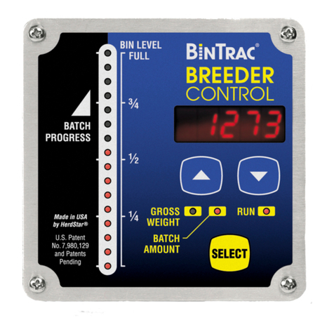
DBTB-200 Dual Breeder Control
Installation Manual
Patented
U.S. Patent No. 7,980,129, Patent No. 8,581,122, Patent No. 8,853,566
U.S. Patent No. 9,310,243, Patent No. 9,651,413, Patent No. 10,082,421
Canada Patent No. 2,822,294
Korea Patent No. 1900521

Installation Manual
Version 1.1 2 Part Number MAN-000014
Table of Contents
Installation Overview ........................................................................................................................................................3
Components................................................................................................................................................................3
Preparation..................................................................................................................................................................4
List of Common Parts to be Installed.....................................................................................................................4
Tools Needed.........................................................................................................................................................4
Supplies Needed....................................................................................................................................................4
Steps to Come.............................................................................................................................................................4
Configurations ............................................................................................................................................................. 5
Installation ........................................................................................................................................................................7
Mount the Bracket Assembly.......................................................................................................................................7
Lift the Bin.................................................................................................................................................................... 7
Anchor the Bin.............................................................................................................................................................8
Wiring the Smart Summing Box ..................................................................................................................................9
Wiring the BinTrac Power Supply..............................................................................................................................10
Wiring the BinTrac Dual Breeder Control..................................................................................................................10
Wiring a BinTrac Indicator as a Remote Display.......................................................................................................11
Addendum A - Unload Relay Wiring Diagram................................................................................................................12
Addendum B - Load Relay Wiring Diagram ...................................................................................................................13
Addendum C - Complete Wiring Diagrams....................................................................................................................14
HerdStar BinTrac®Product Warranty.............................................................................................................................17
BinTrac Breeder Control Startup and Warranty Validation Checklist.............................................................................18
is a registered trademark of HerdStar, LLC.
Copyright © 2022 HerdStar, LLC. All rights reserved.
Printed in the USA
1400 Madison Avenue Suite 504, Mankato, MN 56001
PH: 507-344-8005 FAX: 507-344-8009
www.herdstar.com

Installation Manual
Version 1.1 3 Part Number MAN-000014
Thank you for purchasing a BinTrac Dual Breeder Control System from HerdStar, LLC.
Installation Overview
This section covers the mounting and wiring of the BinTrac system. Anyone responsible for programming and
operating the BinTrac system should also read the Operator’s Manual.
This symbol means the text has extra importance since it is describing the importance of a feature or
explaining a step to which you should pay close attention to avoid problems, or to which safety is a
concern.
Components
A BinTrac system consists of a number of basic components:
BinTrac Dual Breeder Control
This is the main unit of the BinTrac system. The BinTrac Dual Breeder Control communicates with the Smart Summing
Boxes to register the weight of feed in the bins. The feed level is computed and displayed on the LED bar graphs.
One Dual Breeder Control can control two feed bins.
Load Cell Bracket
Four or more load cell brackets allow the BinTrac Dual Breeder Control to accurately measure the feed level in your
bins. The Smart Summing Box averages the signals from all brackets to minimize errors that could result from voids
(holes) in the feed.
Smart Summing Box
One Smart Summing Box per bin communicates the current reading on the leg brackets to the BinTrac Dual Breeder
Control.
BinTrac Power Supply
This provides the power for the BinTrac system. The power supply converts the line voltage to low voltage
BinTrac Remote Display
A BinTrac Remote Display is a standard BinTrac indicator configured as a Remote Display. A hardwire cable must
connect the Remote Display to the BinTrac Dual Breeder Control.
BinTrac Breeder Control Remote Display
A BinTrac Breeder Control Remote Display is a standard BinTrac Breeder Control indicator configured as a Remote
Display. A hardwire cable must connect the Remote Display to the BinTrac Dual Breeder Control.

Installation Manual
Version 1.1 4 Part Number MAN-000014
Preparation
Before beginning the installation process, you need to make sure that the area surrounding each leg is clear of dirt,
ice, or any other debris that may cause the ‘A’ frame to not sit flat. If this is not done it could cause the bin to lift
unevenly and give a false reading.
List of Common Parts to be Installed
•MCA-000221/222 –BinTrac Dual Breeder Control
•MLB-XXXXXX –2.5/5.0K/10k Ag Load Cell Bracket Assembly
•MSA-006000 –Smart Summing Box 6-Leg OR MSA-004000 –Smart Summing Box 4-Leg
•ASY-000237 –BinTrac Power Supply PS17
Tools Needed
•1 –1 1/8” open-end wrench
•2 –3/4” wrenches
•1/2” Drill
•1/2” Hammer drill or Hilti cement drill
•1/2” metal bit
•1/2” cement bit
•5/16” self-tapping screws
•5/16” hex screw tip
•1/2” cordless drill
•Impact wrench with 1 1/8” and 3/4” sockets (optional)
•Small flat-head screwdriver
•#2 Phillips screwdriver
•Center punch
Supplies Needed
•Tie Wraps (2 per leg)
•Wire Nuts (blue or orange, 4 per bin)
•Communication Wire (4 Cond. 20 –22 AWG, shielded)
Steps to Come
There are several steps to install the BinTrac Dual Breeder Control system. To give an overview of the installation
process, these steps are outlined below.
•Mounting the ‘A’ frame
•Lifting the bin
•Anchoring the ‘A’ frame
•Wiring the Smart Summing Box
•Setting the Smart Summing Box bins
•Wiring the Power Supply
•Wiring the BinTrac Dual Breeder Control
Please read through the entire installation process before attempting to install a BinTrac Dual
Breeder Control System. If you have any questions, do not hesitate to contact HerdStar or a
certified dealer in your area.

Installation Manual
Version 1.1 5 Part Number MAN-000014
Configurations
The BinTrac Dual Breeder Control can be used in different configurations based on your needs. Before beginning the
setup of your system, determine which configuration you will be using. Below is an overview of the different
configurations of batching. Included with each BinTrac Dual Breeder Control is a sheet of labels that can be used to
identify the functionality of each side of the display.
Inventory Bin with Dual Breeder (Dual Unload Batch Method)
The Dual Breeder Console can be connected to a single inventory bin equipped with BinTrac load cells. The Dual
Breeder Console incorporates two Breeder Controllers within a single enclosure, one Unload Control (Master)
assigned to the Rooster feeding system and one Unload Control (Remote) assigned to the Hen feeding system. Each
controller within the Dual Breeder Console is programmed to batch independent amounts of feed on separately
controlled feed delivery systems.
Weigh Bin with Dual Breeder (Unload and Load Batch Method)
The Dual Breeder Console can be connected to a single weigh bin equipped with BinTrac load cells. The Dual
Breeder Console incorporates two Breeder Controllers within a single enclosure, one Unload Control (Master)
assigned to deliver feed from the weigh bin into the house and one Load Control (Remote) assigned to deliver
feed from the inventory bin into the weigh bin. Each controller within the Dual Breeder Console is programmed to
batch independent amounts of feed on separately controlled feed delivery systems.

Installation Manual
Version 1.1 6 Part Number MAN-000014
Weigh Bin with Triple Breeder (Load and Dual Unload Batch Method)
The Single BinTrac Breeder Control and a Dual Breeder Console can be connected to a single weigh bin equipped
with BinTrac load cells. The Dual Breeder Console incorporates two Breeder Controllers within a single enclosure,
one Unload Control (Master) assigned to the Rooster feeding system and one Unload Control (Remote) assigned to
the Hen feeding system. The Single BinTrac Breeder Control (Remote) is assigned to deliver feed from the inventory
bin into the weigh bin. Each BinTrac Breeder Controller within this scenario are programmed to batch independent
amounts of feed on separately controlled feed delivery systems.

Installation Manual
Version 1.1 7 Part Number MAN-000014
Installation
Mount the Bracket Assembly
1. Remove all bolts connecting the leg to the footpad. Loosen the original
anchor bolt but leave it intact at the bottom of the footpad. The footpad
can and should be removed if it is binding or interfering with lifting the
leg. (Figure 1)
2. Remove the 1/2” bolts from the C-channel adapter of the bracket
assembly and set them aside for now.
3. Adjust the top bolt on the bracket assembly so the C-channel is
approximately 3/4” between the top of the C-channel and the bracket.
4. Mark the holes of the C-channel on the leg and drill using 1/2” drill bit.
(Figure 2)
5. Put the bolts in from the C-channel side through the leg. Place a washer
and Nyloc nut on each bolt and hand-tighten.
6. Position the bracket assembly so that it is 3/8” away from the bin leg and
the C-channel is centered under the load cell.
Failure to properly align the bracket may cause the load
cell to fail.
7. Hand-tighten the top bolt on the bracket assembly to make sure the
bracket is straight and to keep it in place.
8. Tighten C-channel bolts to 33 ft-lbs. of torque. Make sure the
bracket does not move during tightening.
Lift the Bin
9. Using a marker, place a line the top of the bolt. (Figure 3)
10. Tighten all the lifting bolts 1 or 2 full turns at a time until each leg
is at 8 turns.
11. There must be a ½” (+/- 1/8”) gap underneath each leg when
lifting is complete. (Figure 4)
12. The top of the C-channel MUST NOT be up against the bracket
assembly: a clearance of 1/4” (+/- 1/8”) must be maintained.
(Figure 5)
13. Be sure to check height of each leg and verify the bracket is not
touching the leg.
Figure 1: Remove bolts from bin leg
IMPORTANT: MOUNT THE BRACKET ASSEMBLY ONE (1) LEG AT A TIME.
DETACHING MORE THAN ONE LEG AT A TIME COULD ALLOW THE BIN TO TIP
OVER. INJURY OR DEATH COULD RESULT!
Figure 2: Mark holes of the C-Channel on the legs
Figure 3: Place a line centered on top of bolt.

Installation Manual
Version 1.1 8 Part Number MAN-000014
Repeat Steps 1 –13 for all bin legs. After completing steps 1-13 for each leg (and
before continuing to step 14), re-examine each leg to ensure proper clearances as
noted and adjust as needed.
Anchor the Bin
14. Drill two anchor bolt holes 2 1/4” deep in the pad diagonally
opposite of each other. (Figure 6)
When anchoring 15K or greater assemblies you
will use four (4) anchor bolts.
15. Hammer bolts into cement until they are firmly in place.
16. Tighten the nuts of the anchor bolts using a socket or hammer drill to
anchor the bracket assembly. Torque to 55 ft.-lbs.
17. Drop retention clip into place over bolt as shown in Figure 7.
Figure 6: Drill anchor bolts 2 1/4" deep.
Figure 4: Lift until there is a 1/2" (+/- 1/8”) gap.
Figure 5: Leave 1/4” (+/- 1/8”) gap between C-
channel and bracket.
Figure 7: Retention clip (shaded) over bolt

Installation Manual
Version 1.1 9 Part Number MAN-000014
Wiring the Smart Summing Box
In order to get a reading from the load cells, you need to tie them all together into a Smart Summing Box. One Smart
Summing Box per bin is required. Refer to Addendums A through C for more in depth wiring illustrations.
18. Mount the Smart Summing Box (SSB) on the crossbar under the bin near the front using self-tapping screws
where it is easily accessible for maintenance.
19. Run the cable from each load cell to the Smart Summing Box.
20. Before plugging the cables in, remove the black plastic lock nut from each cable strain relief. Remove the red
plug from each predrilled hole. Pass the cable through the box and then the nut. Be sure to have a drip loop
outside the SSB.
21. Plug in the load cells starting in the upper left until all
load cells are plugged in.
22. Pass the communication cable through the gray liquid
tight strain relief on the right side of the enclosure.
23. Using an appropriately sized wire nut, connect the
wires according to the chart in Figure 8.
24. Attach the GREEN/YELLOW ground wire to the bin
via one of the screws used to attach the SSB.
25. Run the communication wire to the BinTrac Dual Breeder
Control.
26. Tighten every strain-relief (“dome nut”) on the box. First, tighten the nuts to attach the strain reliefs to the box.
Then, tighten the dome nut until the cable cannot be pulled out of the box.
27. Set the bin to A using the dip switches inside the summing box. (Figure 9).
BIN S1 S2 S3 S4
AOFF OFF OFF OFF
BON OFF OFF OFF
COFF ON OFF OFF
DON ON OFF OFF
Figure 8: Connect wires following the above chart.
Figure 9: Set appropriate bin using dipswitch.

Installation Manual
Version 1.1 10 Part Number MAN-000014
Wiring the BinTrac Power Supply
28. The Power Supply (PS17) is intended for inside use. As the BinTrac Breeder Control is installed in an office
or building walkway, the Power Supply can be installed in the same area near an outlet.
29. Mount the Power Supply in a location that allows the 12VDC cable to be ran a short distance to the Breeder
Control unit.
30. Once the cable is routed from the Power Supply to the BinTrac Breeder Control and has been tied up out of
the way, cut off any excess cable and connect into Breeder Control unit as shown below.
Wiring the BinTrac Dual Breeder Control
31. Locate the terminal block in the BinTrac Dual Breeder Control labeled ‘SUMMING BOX’(see Figure 10).
32. Insert the wires into the terminal block where RED is 12V OUT (+), GREEN is COM IN (+), WHITE is COM IN
(-), and BLACK is 12V OUT (-).
33. Connect the wires from the BinTrac power supply to the terminal block labeled ‘POWER INPUT’ (see Figure
10) where WHITE is 12V IN (+) and BLACK is 12V IN (-).
34. After wiring the Smart Summing Box to the BinTrac Dual Breeder Control Indicator, you will then wire the
Auger Relay to the BinTrac Dual Breeder Control Indicator as shown in the addendums (pages 11 through
14). A voltage suppressor is provided with the Relay Kit (KIT-000028) and is to be connected across the
Auger Relay coil. In addition, an auto/manual override switch is included in the kit and should be installed as
well.
Reference Addendum C for complete system wiring diagrams for each configuration.
Figure 10: Insert wires in appropriate terminal
block.

Installation Manual
Version 1.1 11 Part Number MAN-000014
Wiring a BinTrac Indicator as a Remote Display
A Remote Display is a BinTrac Indicator (BT200 / BT260) programmed as a Remote Display which displays the same
weight data as the local BinTrac Dual Breeder Control. The Remote Display receives all of its settings (except for
enabled bins) from the BinTrac Dual Breeder Control. Calibration and Zero must be done on the BinTrac Dual
Breeder Control.
1. Connect the wiring between the Remote Display and the BinTrac Dual Breeder Control. Power can be
supplied directly to the Remote Display or from the BinTrac Dual Breeder Control.
BinTrac Dual Breeder
Control Indicator
DBTB200
ADDITIONAL
REMOTE BINTRAC
BinTrac Indicator
(BT200) programmed
as Remote Display
PWR OUT +12V
COMM +12V
COM IN (+)
COMM +SIG
COM IN (-)
COMM –SIG
PWR OUT -12V
COMM -12V
BinTrac Dual Breeder
Control Indicator
DBTB200
ADDITIONAL
REMOTE BINTRAC
BinTrac Indicator
(BT260) programmed
as Remote Display
PWR OUT +12V
12V IN+
COM IN (+)
+COM OUT
COM IN (-)
-COM OUT
PWR OUT -12V
12V IN-
Figure 11: DBTB200 ADDITIONAL BINTRAC REMOTE port
to COMM port on BT200 Remote Indicator
Figure 12: DBTB200 ADDITIONAL BINTRAC REMOTE port
to 12V IN and COM OUT port on BT260 Remote Indicator

Installation Manual
Version 1.1 12 Part Number MAN-000014
Addendum A –Dual Unload Relay Wiring Diagram
Below is a reference diagram for wiring up the Dual Breeder Control for a Dual Unload Batch Method.
Please reference BinTrac Part # KIT-000028
Item #
Part Number
Part Description
Qty
1
REL-000017
RELAY GEN PURPOSE DPDT 10A 125V (K1)
2
2
CON-000126
SOCKET RELAY 8 OCTAL DIN RAIL
2
3
ASY-000213
ASY VOLTAGE SUPPRESSOR
2
4
SWI-000025
SWITCH TOGGLE SPDT 5A ON-OFF-ON (SW1)
2
5
SWI-000026
TOGGLE SWITCH BOOT
2

Installation Manual
Version 1.1 13 Part Number MAN-000014
Addendum B –Unload/Load Relay Wiring Diagram
Below is a reference diagram for wiring up the Dual Breeder Control for a Unload/Load Batch Method.
Please reference BinTrac Part # KIT-000028
Item #
Part Number
Part Description
Qty
1
REL-000017
RELAY GEN PURPOSE DPDT 10A 125V (K1)
2
2
CON-000126
SOCKET RELAY 8 OCTAL DIN RAIL
2
3
ASY-000213
ASY VOLTAGE SUPPRESSOR
2
4
SWI-000025
SWITCH TOGGLE SPDT 5A ON-OFF-ON (SW1)
2
5
SWI-000026
TOGGLE SWITCH BOOT
2

Installation Manual
Version 1.0 13 Part Number MAN-000014
Addendum C - Complete Wiring Diagrams

Installation Manual
Version 1.1 15 Part Number MAN-000014

Installation Manual
Version 1.1 16 Part Number MAN-000014

Installation Manual
Version 1.0 15 Part Number MAN-000014
HerdStar BinTrac® Product Warranty
HerdStar, LLC (“HerdStar”) warrants to original purchaser (“Buyer”) that goods manufactured solely by HerdStar, LLC
(“Products”) will be free from defects in material or workmanship under normal and intended use and service for a
period of one year from delivery date of the Products. Used and/or refurbished parts sold shall carry a 90-day warranty
on material and workmanship. All warranty claims must be submitted within ten (10) days of discovery of defects within
the warranty period or shall be deemed waived. Furthermore, HerdStar, LLC warrants the load cell (“Load cell” is defined
as the s-shaped component and any cabling and connectors) against lightning damage for 12 months or the term of
any extended warranty.
In the event of a defect in any Products constituting a breach of the warranty provided herein, HerdStar, LLC will at its
option either (i) repair or replace such Product free of charge, or (ii) in lieu of repair or replacement, refund to Buyer the
original purchase price less the reasonable value of Buyer’s use of the Products. HerdStar, LLC shall furnish to Buyer
instructions for the disposition of the defective goods. HerdStar, LLC shall have the option of requiring the return of the
defective goods, transportation prepaid, and proof that the goods were not used, installed or altered or subject to misuse
or abuse to establish the claim. No goods shall be returned to HerdStar, LLC without its prior consent. The acceptance
of any goods returned to HerdStar, LLC shall not be deemed an admission that the goods are defective or in breach of
any warranty, and if HerdStar, LLC determines that the goods are not defective they may be returned to Buyer at Buyer’s
expense. This warranty sets forth Buyer’s sole and exclusive remedies for any defect in the goods. The rights and
obligation under this warranty may not be assigned or delegated to a third party by Buyer without the prior written
permission of HerdStar, LLC. Neither Buyer nor any other person may modify or expand the warranty provided herein,
waive any of the limitations, or make any different or additional warranties with respect to the Products. Any statements
to the contrary are hereby rendered null and void unless expressly agreed to in writing by an authorized officer of
HerdStar, LLC.
EXCEPT AS STATED IN ABOVE, HERDSTAR, LLC DOES NOT MAKE ANY WARRANTY AS TO THE GOODS OR
SERVICES AND, IN PARTICULAR, DOES NOT MAKE ANY WARRANTY OF MERCHANTABILITY OR FITNESS FOR
ANY PARTICULAR PURPOSE, AND BUYER IS SOLELY RESPONSIBLE FOR DETERMINING THE PROPER
APPLICATION AND USE OF THE GOODS.
HerdStar, LLC makes no representation or warranty that individual animals, or any given population of animals, will
utilize any of HerdStar, LLC’s goods in the manner for which the goods were intended or designated. Any component
parts that are not manufactured by HerdStar, LLC, such as electrical motors and controls, are excluded from any warrant
by HerdStar, LLC, although such parts may be covered by separate warranties of the respective manufacturers. This
warranty set forth above does not apply if all components of a system are not supplied by HerdStar, LLC or if the goods
are not purchased from and installed by an authorized distributor or company warehouse, or installed and operated in
accordance with HerdStar, LLC’s specifications and instructions.
HERDSTAR, LLC SHALL NOT HAVE ANY TORT LIABILITY TO BUYER OR ANY OTHER PERSON WITH RESPECT
TO ANY OF THE GOODS OR SERVICES AND SHALL NOT BE LIABLE FOR CONSEQUENTIAL, INCIDENTAL,
SPECIAL, EXEMPLARY, INDIRECT OR PUNITIVE DAMAGES ARISING FROM ANY PRODUCT DEFECT, DELAY,
NONDELIVERY, RECALL OR OTHER BREACH. BUYER SHALL NOT HAVE ANY RIGHT OF REJECTION OR OF
REVOCATION OF ACCEPTANCE OF THE GOODS.

Installation Manual
Version 1.1 18 Part Number MAN-000014
BinTrac Breeder Control Startup and Warranty
Validation Checklist
A-Frame Bracket Inspection Checklist –Reference figures below
☐☐Proper C-Channel clearance –Figure 1
☐☐Bin leg properly lifted off the concrete pad –Figure 2
☐☐Proper clearance between bin leg and A-Frame Bracket –Figure 3
Smart Summing Box and Load Cell Inspection
☐☐Drip loops at all connection points (Smart Summing Box and load cells)
☐☐Mounted on an interior crossmember to avoid excessive water exposure
☐☐Proper High Voltage AC & DC wiring separation
☐☐Inspect load cell cables for damage from Smart Summing Box to load cell
BinTrac Breeder Control(s) –Refer to Operator’s manual for Controller setup & installation scenarios
☐☐“Setup” – Reference the manual to verify the controller is correctly set as a Master or
Remote depending on your installation scenario
☐☐“b.tyPE” Setup – Load or Unload –depending on your installation scenario
☐☐“S.CYCL” Setup – On or Off. Default is off.
☐☐“Rated” Setup = 3.000
☐☐“L.C.CAP” Setup = Load cell capacity multiplied by the number of legs on the bin
☐☐“Incr” Setup = User defined. Default is 1
☐☐“Full” Setup – Material capacity of bin
☐☐“Zero” Setup – Empty weight of bin
☐☐“Year” Setup – Verify
☐☐“Month” Setup – Verify
☐☐“Date” Setup – Verify
☐☐“Hour” Setup – Verify NOTE: Hour is displayed in 24-hour (military) time & is set to CST by default
☐☐“Minute” Setup – Verify
☐☐“id” = User defined. Default is 1
Figure 1
Figure 2
Figure 3
Yes No
Yes No
Yes No

Installation Manual
Version 1.1 19 Part Number MAN-000014
General Inspection and Notes
☐☐BinTrac Indicator is weighing correctly when applying a known load to each bin leg.
☐☐Electrical Conduit –Proper routing with flexible connections so that no binding or load is being
applied to the bin.
☐☐Feedline(s) properly supported & not binding or applying additional load to the bin.
☐☐Relay kit with on/off/auto switch is properly installed and functioning.
☐☐Ensure retention clips are placed over bolts on top of each A Frame (see Page 8, Figure 7)
NOTES_______________________________________________________________________________________
_____________________________________________________________________________________________
_____________________________________________________________________________________________
_____________________________________________________________________________________________
_____________________________________________________________________________________________
_____________________________________________________________________________________________
**WARNING**
If “No” is checked for any of these items, please consult your dealer as it may affect the performance and warranty on
this system.
Site Name and Location ______________________________________________________________
Inspected by _______________________________________________________________________
Date _____/_____/_____
Please fill out and return a copy to:
BinTrac by HerdStar
1400 Madison Ave Suite 504
Mankato, MN 56001
Phone - 507-344-8805
Fax –507-344-8009
Email –service@herdstar.com
Website - www.bintrac.com
Yes No
Table of contents
Other herdstar Control Unit manuals