manuals.online logo
Brands
  1. Home
  2. •
  3. Brands
  4. •
  5. Fike
  6. •
  7. Control Unit
  8. •
  9. Fike FIK-M500M User manual

Fike FIK-M500M User manual

BEFORE INSTALLING
This information is included as a quick reference installation guide. Refer to
the control panel installation manual for detailed system information. If the
modules will be installed in an existing operational system, inform the opera-
tor and local authority that the system will be temporarily out of service. Dis-
connect power to the control panel before installing the modules.
NOTICE: This manual should be left with the owner/user of this equipment.
GENERAL DESCRIPTION
The FIK-M500M Monitor Module is intended for use in intelligent, two-wire
systems, where the individual address of each module is selected using the
built-in rotary switches. It provides either a Class A or Class B fault tolerant
initiating device circuit (IDC) for normally open contact fire alarm and super-
visory devices, or either normally open or normally closed security devices.
The module has a panel controlled LED indicator.
COMPATIBILITY REQUIREMENTS
To ensure proper operation, this module shall be connected to a compatible
Fike system control panel (list available from Fike).
FIGURE 1. CONTROLS AND INDICATORS
C1067-00
MOUNTING
The FIK-M500M mounts directly to 4-inch square electrical boxes. (See
Figure 2.) The box must have a minimum depth of 21⁄8inches. Surface
mounted electrical boxes (SMB500-WH) are available from Fike.
FIGURE 2. MODULE MOUNTING
NOTE: For UL Listed security installations, the FIK-M500M must be mounted
within the control panel enclosure.
ISOLATED
QUADRANT
C1066-00
WIRING
NOTE: All wiring must conform to applicable local codes, ordinances, and
regulations. This module is intended for power limited wiring only.
1. Install module wiring in accordance with the job drawings and appropri-
ate wiring diagrams.
2. Set the address on the module per job drawings.
3. Secure module to electrical box (supplied by installer), as shown in Figure 2.
NOTE: All references to power limited represent “Power Limited (Class 2)”.
SPECIFICATIONS
Normal Operating Voltage: 15 to 32 VDC
Maximum Current Draw: 5.0 mA (LED on)
Average Operating Current: 375µA (group poll),
350 µA (direct poll),
600 µAmps (communication, IDC shorted)
EOL Resistance: 47K Ohms
Max. IDC wiring resistance: 1,500 Ohms
Maximum IDC Voltage: 11 Volts
Maximum IDC Current: 450µA
Temperature Range: 32°F to 120°F (0°C to 49°C)
Humidity: 10% to 93% Non-condensing
Dimensions: 4½" H x 4" W x 1¼" D (Mounts to a 4" square by 2
⅛
" deep box.)
Accessories: SMB500-WH Electrical Box
I56-6671-001
INSTALLATION AND MAINTENANCE INSTRUCTIONS
R
704 SW 10th Street
Blue Springs, MO 64015
Phone: 816.229.3405; Fax: 816.228.9277
www.fike.com
FIK-M500M Monitor Module
http://www.fike.com/06-912
Fo
r system/product documentation including
installation, operation, and maintenance,
scan QR code or enter URL provided.
1 I56-6671-001
10/5/2021
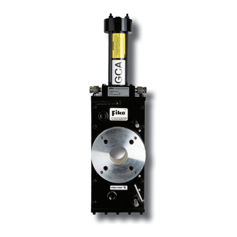
FIGURE 3. TYPICAL 2-WIRE INITIATING CIRCUIT CONFIGURATION, NFPA CLASS B OR SECURITY SYSTEMS
NOTE: For UL Listed security installations, the FIK-M500M must be mounted within the control panel enclosure.
(+)
(–)
(+)
(–)
(+)
(–)
MONITOR
MODULE
ANY NUMBER OF UL LISTED CONTACT
CLOSURE DEVICES MAY BE USED. DO NOT MIX
FIRE ALARM INTIATING, SUPERVISORY, OR
SECURITY DEVICES ON THE SAME MODULE.
TO NEXT
DEVICE
FROM PANEL OR
PREVIOUS DEVICE
47K EOL
RESISTOR
ELR-47K
CONNECT MODULES TO LISTED COMPATIBLE
CONTROL PANELS ONLY
SIGNAL LINE CIRCUIT (SLC)
32 VDC MAX.
TWISTED PAIR
IS RECOMENDED
ALL WIRING SHOWN IS SUPERVISED AND POWER LIMITED
INITIATING DEVICE CIRCUIT (IDC) - NFPA STYLE B
POWER LIMITED: 450µA MAX. @ 11 VDC MAX
INSTALL CONTACT CLOSURE DEVICES PER
MANUFACTURER’S INSTALLATION INSTRUCTIONS.
C0918-00
FIGURE 4. TYPICAL 4-WIRE FAULT TOLERANT INITIATING CIRCUIT CONFIGURATION, NFPA CLASS A
(+)
(-)
(+)
(–)
(+)
(–)
TO NEXT
DEVICE
ANY NUMBER OF UL LISTED CONTACT
CLOSURE DEVICES MAY BE USED. DO NOT MIX
FIRE ALARM INTIATING, SUPERVISORY, OR
SECURITY DEVICES ON THE SAME MODULE.
MONITOR
MODULE
FROM PANEL OR
PREVIOUS DEVICE
CONNECT MODULES TO LISTED COMPATIBLE
CONTROL PANELS ONLY
SIGNAL LINE CIRCUIT (SLC)
32 VDC MAX.
TWISTED PAIR
IS RECOMENDED
ALL WIRING SHOWN IS SUPERVISED AND POWER LIMITED
INSTALL CONTACT CLOSURE DEVICES PER
MANUFACTURER’S INSTALLATION INSTRUCTIONS.
EOL RESISTOR IS
INTERNAL AT
TERMINALS 8 & 9
C0919-00
DEVICE AND SYSTEM SECURITY
Before installing this product ensure that the tamper
seal on the packaging is present and unbroken and
the product has not been tampered with since leaving
the factory. Do not install this product if there are
any indications of tampering. If there are any signs
of tampering the product should be returned to the
point of purchase.
It is the responsibility of the system owner to ensure
that all system components, i.e. devices, panels, wir-
ing etc., are adequately protected to avoid tampering
of the system that could result in information disclo-
sure, spoofing, and integrity violation.
2 I56-6671-001
©2021. 10/5/2021
Fike® is a registered trademark of Fike Corporation.

This manual suits for next models

1

Other Fike Control Unit manuals

Fike FIK-FML Technical manual

Fike

Fike FIK-FML Technical manual

Fike 55-043 User manual

Fike

Fike 55-043 User manual

Fike P Service manual

Fike

Fike P Service manual

Fike FAV User manual

Fike

Fike FAV User manual

Fike TWINFLEX IRM 100-0011 User manual

Fike

Fike TWINFLEX IRM 100-0011 User manual

Fike TWINFLEX SRM 100-0010 User manual

Fike

Fike TWINFLEX SRM 100-0010 User manual

Fike 55-046 User manual

Fike

Fike 55-046 User manual

Fike MICROMIST 10-2340 User manual

Fike

Fike MICROMIST 10-2340 User manual

Fike FIK-CR-6 User manual

Fike

Fike FIK-CR-6 User manual

Fike EIV User manual

Fike

Fike EIV User manual

Fike Lantronix XPort 10-2627 Operating instructions

Fike

Fike Lantronix XPort 10-2627 Operating instructions

Fike FIK-IM-10 User manual

Fike

Fike FIK-IM-10 User manual

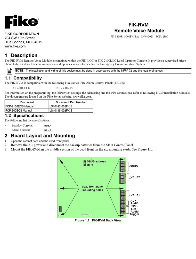
Fike FIK-RVM User manual

Fike

Fike FIK-RVM User manual

Popular Control Unit manuals by other brands

DoorHan CV01 Installation and operation guide

DoorHan

DoorHan CV01 Installation and operation guide

Skylab WG209-User user manual

Skylab

Skylab WG209-User user manual

handtmann INOVA operating manual

handtmann

handtmann INOVA operating manual

NI REM-11178 Getting started guide

NI

NI REM-11178 Getting started guide

Johnson Controls Tyco DV-5a Series manual

Johnson Controls

Johnson Controls Tyco DV-5a Series manual

ABB ControlNet FCNA-01 Quick installation and start-up guide

ABB

ABB ControlNet FCNA-01 Quick installation and start-up guide

Dewetron DAQP-LV Technical reference manual

Dewetron

Dewetron DAQP-LV Technical reference manual

Panasonic PAN1782 Product specification

Panasonic

Panasonic PAN1782 Product specification

Huawei MG323 AT Command Interface Specification

Huawei

Huawei MG323 AT Command Interface Specification

curt VENTURER Installation and user guide

curt

curt VENTURER Installation and user guide

CLA-VAL 90-48 Installation operation & maintenance

CLA-VAL

CLA-VAL 90-48 Installation operation & maintenance

WAGO I/O-SYSTEM 751-3001 manual

WAGO

WAGO I/O-SYSTEM 751-3001 manual

Wisi OM 17A operating instructions

Wisi

Wisi OM 17A operating instructions

CAME TOP Series quick start guide

CAME

CAME TOP Series quick start guide

Yamatake ACTIVAL VY51X2J Specifications & instructions

Yamatake

Yamatake ACTIVAL VY51X2J Specifications & instructions

emaux FLEX Series Installation and operation manual

emaux

emaux FLEX Series Installation and operation manual

Intermatic ET9232 Replacement instructions

Intermatic

Intermatic ET9232 Replacement instructions

Dembla GTV - 01 Series instruction manual

Dembla

Dembla GTV - 01 Series instruction manual

manuals.online logo
manuals.online logoBrands
  • About & Mission
  • Contact us
  • Privacy Policy
  • Terms and Conditions

Copyright 2025 Manuals.Online. All Rights Reserved.