HERKULES L1200S User manual
Part# 1002868-04
1/23/2017
1002868 (L1200S) - 04.xlsx
This manual contains important information concerning the
installation and operation of the automobile lift listed above.
Read manual thoroughly and keep for future reference
INSTRUCTIONS
Herkules Equipment Corporation 2760 Ridgeway Court Walled Lake, MI 48390-1662 USA
248-960-7100 800-444-4351 Fax 248 960-7109
Patents USA 7070167 4793369, 4960142, 5174317, 5193561, 5485860 Canada 1299468 & Patents Pending
Page 1 of 15

Warnings ………………………………………………………………………………………………………………………………… 2 - 4
Installation …………………………………………………………………………………………………………………..…………… 5 - 7
Operation …………………………………………………………………………………………………………………….…………… 8
Duty Cycle ……………………………………………………………………………………………………….…………………… 9
Ratch Operation ……………………………………………………………………………………………………….……………… 9
Maintenance Instructions ……………………………………………………………………………………………………….……. 10
Troubleshooting ………………………………………………………………………………………………………………………… 10
Optional Accessories ………………………………………………………………………………………………………………….. 11
Parts List ………………………………………………………………………………………………………………………………… 12
Controller Layout ………………………………………………………………………………………………………………………… 13
Layout Drawing ………………………………………………………………………………………………………………………… 14
Schematic ……………………………………………………………………………………………………………………………… 15
Warning Symbol Caution Symbol
Serial Number
Model Number
Purchase Date
Distributor
The limited liability warranty applies to the pneumatic chambers of our Herkules lifts and to the initial user against defective
materials for a period of five years from the proof of purchase date. The limited liability warranty applies to other
components of our Herkules lifts to the initial user against defective materials for a period of one year from the proof of
purchase date.
This warranty does not apply to equipment damaged from accident, abuse, overload, misuse, negligence, improper
installation, abrasive or corrosive materials, or shipping damage.
In the event of failure, the defective item must be returned, freight prepaid, to the Herkules manufacturing plant for repair
or replacement. If repairs are required Herkules will not be liable for these repairs to take place in the field regardless
of the application. Proof of purchase and date of purchase must be confirmed. An RGA number (Return Goods
Authorization) and written approval from Herkules must be obtained before any goods can be shipped to Herkules. Herkules
reserves the right to determine whether the cause of failure is due to defective material, normal wear, and/or other causes.
There are no warranties which extend beyond the description on the face hereof. Herkules disclaims any
warranty of merchantability or fitness for a particular purpose in connection with the Buyer’s purchase
of any Product under this agreement. Damages are limited to the sales price of the Herkules system.
The terms and conditions herein represent the entire agreement between Herkules and the Buyer.
Any prior / future representations do not apply.
Table of Contents
Limited Liability Warranty
CAUTION
WARNING
This symbol alerts you to the possibility of serious
injury or death if you do not follow the instructions. This symbol alerts you to the possibility of damage to or
destruction of equipment if you do not follow the
instructions.
This product has patent protection under
one or more of the following patent numbers:
7070167, 5485860, 5193561, 5174317
4960142, 4793369, 1299468
and Patents Pending
website: www.herkules.us
1002742
PATENT NUMBERS
Page 2 of 15

Tags - Operating Instructions
Warning:
This symbol alerts you to the possibility of serious injury or death if you do not follow
the instructions
Caution:
This symbol alerts you to the possibility of damage to or destruction of equipment if
you do not follow the instructions.
I.
Tag - Operating Instructions (P/N 1006355) Front
Page 3 of 15

I. Tag - Operating Instructions (P/N 1006355) Back
II. Tag - Operating Instructions - Air (P/N 1006356)
Page 4 of 15

Locate lift on a level surface in a position most convenient for the loading and unloading of vehicles.
Obtain hose clamps
ID Part # Description Qty.
1 720-122 CLAMP HOSE # 4 SS/Z 1
2 1001942 CLAMP HOSE CRIMP TYPE 1" Z 1
Using the 1" hose clamp (1001942), clamp the 5/8" ID air line (1001274) from the lift to 5/8" hose barb (1001393) on the
foot control assembly (see fig.1).
Using the #4 hose clamp (720-122), clamp the 1/4" ID air line (720-106) from the lift to hose barb (990) on the foot
control assembly (see fig.1).
NOTE: Check these connections periodically to prevent leakage.
Obtain 1/2 NPT connector compatible with the quick disconnect on your shop air line.
NOTE: Connector not supplied with lift.
Install 1/2 NPT connector into open port (Port 1) on the foot control valve (see fig.2).
Connect your shop air line to connector and test for proper operation.
NOTE: Must use clean, dry air only. Herkules recommends using a filter/regulator (see Optional Accessories).
Installation
STEP 1
STEP 2
STEP 3
STEP 5
STEP 6
STEP 7
STEP 4
fig.2fig.1
5/8" Hose barb
1001393
1/4" Hose barb
990 Port 1
Page 5 of 15
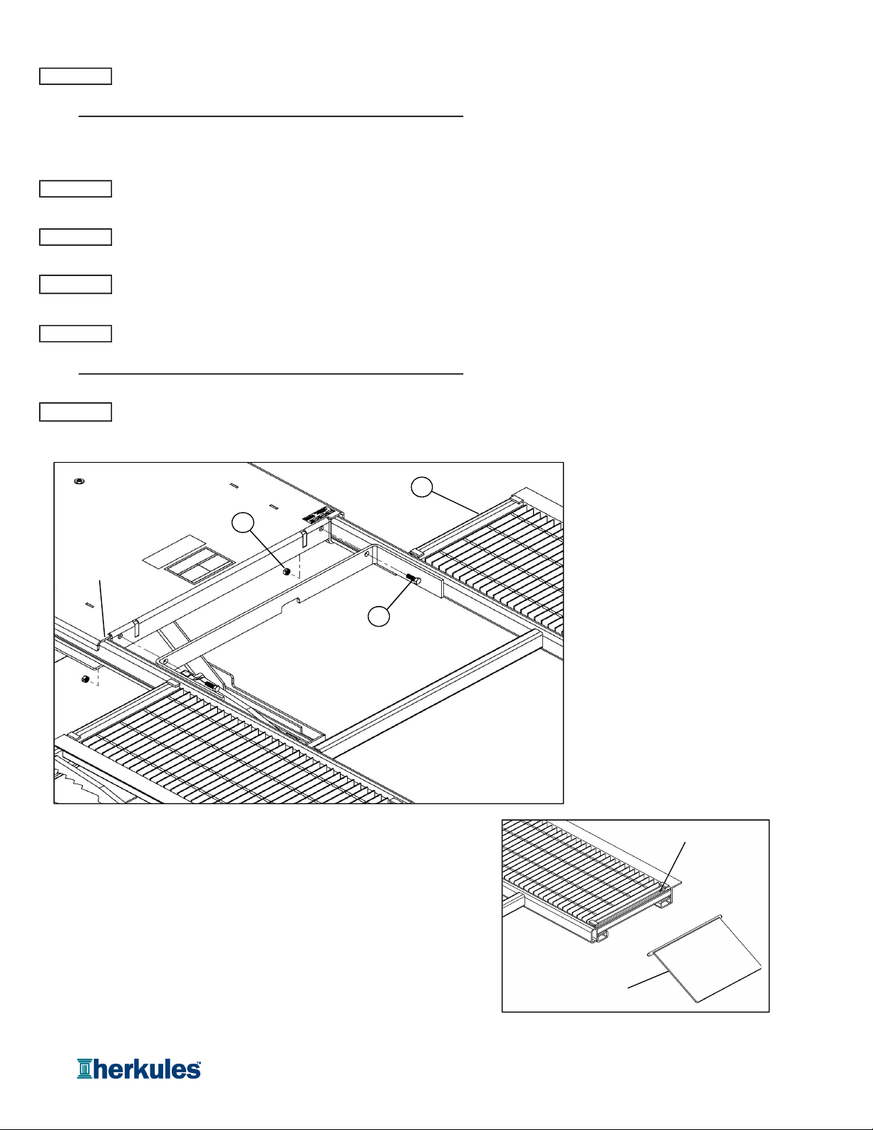
Obtain wing assemblies and hardware: (see fig.3).
ID Part # Description Qty.
1 10527 Wing Assembly 2
2 83J Hex Bolt 1/2-13 x 1-1/2" 4
3 84J Lock Nut 1/2-13 4
Slide the wing assembly (10527) into the wing guides on the top pan of the lift (see fig.3).
Secure the wing assembly to the lift using (2) 1/2-13 x 1-12" hex bolts (83J) and (2) 1/2-13 lock nuts (84J) (see fig.3).
Repeat steps 9-10 for the opposite side wing assembly.
Obtain ramps: (see fig.4).
ID Part # Description Qty.
1 10182 Ramp for Suspension Kit 8
Install each ramp to the wings by inserting the round bar into the ramp tube on the wings (see fig.4).
fig.3
fig.4
STEP 8
STEP 13
STEP 9
STEP 10
STEP 11
STEP 12
Ramp
Ramp Tube
3
1
2
Wing Guide
Page 6 of 15

Move the lift clear of the location and drill the (4) anchor holes with a 7/8" diameter drill to a depth of 2-1/4".
Insert the anchors (008-384) into the drilled holes, making sure that the threaded cone end is inserted first (see fig.6).
Return the lift to the desired position and install (4) 1/2" x 2-1/2" hex bolts (008-385, provided) (see fig.6).
NOTE: Fig.5 shows only lift bottom pan for clarity.
fig.5
fig.6
STEP 17
STEP 15
STEP 16
Anchor Locations
1/2" x 2-1/2" Hex Bolt
008-385
1/2" Anchor
008-384
Page 7 of 15
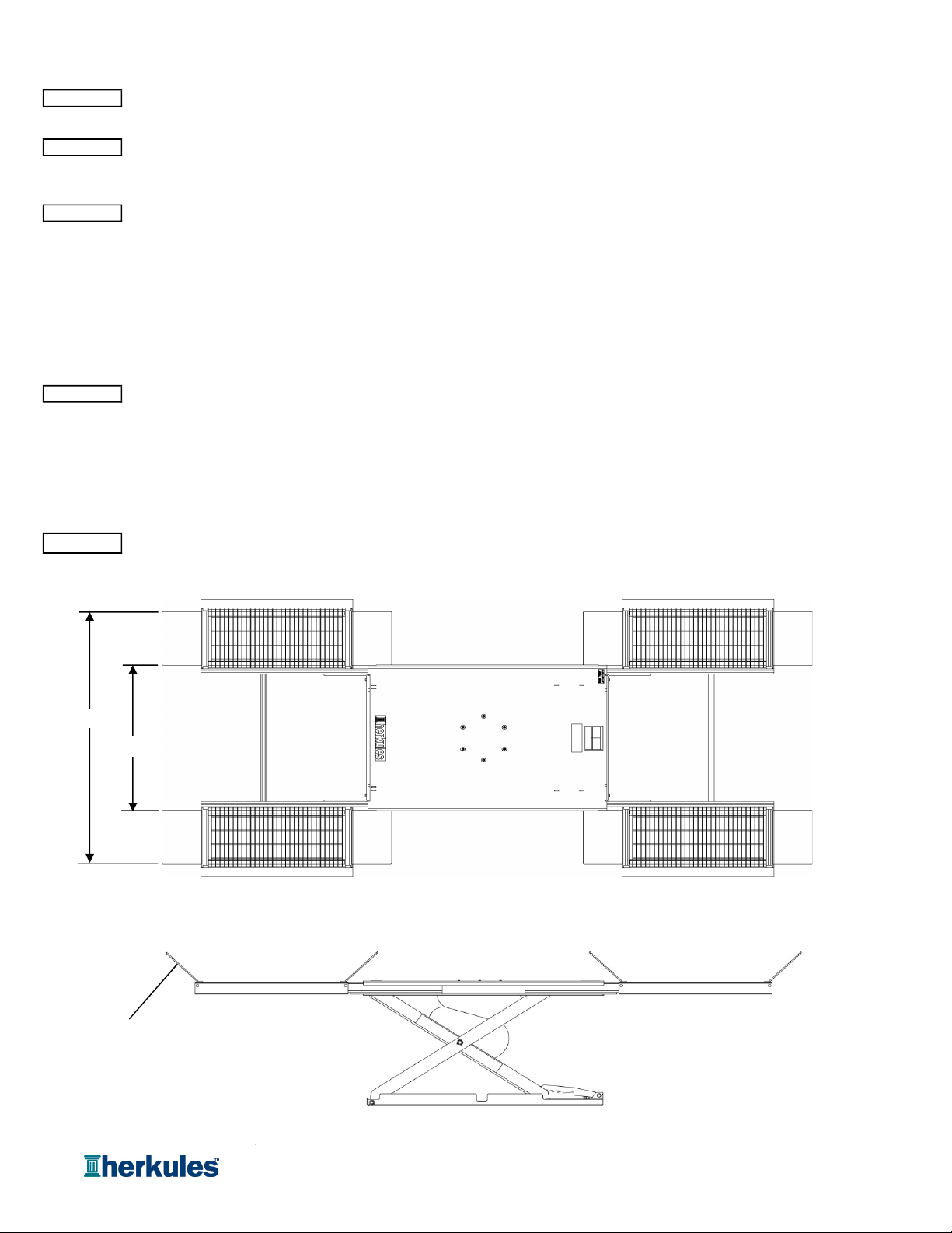
Check the weight of the vehicle to be sure that it does not exceed the rated load capacity of the lift:
5
,000 lbs.
Drive the vehicle onto the lift so that it is approximately centered by weight over the center of the lift. Once the vehicle
is in the desired position, set parking brake and put the ramps into the locked position by tilting them up (see fig.8).
To raise the lift, press the pedal of the foot controller assembly toward the UP position. Hold the pedal in the UP position
until vehicle has reached the desired working height, then release. The mechanical safety arms will automatically
fall into position as the lift rises.
Do not continue to push the control lever after lift is fully raised, even though safety valve will prevent
over-inflation of air bag.
NOTE: Check the stability of the vehicle during the lifting process, and when vehicle is at desired working height.
If vehicle is unstable, immediately stop the lifting process, slowly lower the lift and reposition the vehicle.
To lower the lift, press the pedal of the foot controller assembly towards the DOWN position. Hold the pedal in the DOWN
position until the lift is completely lowered. The mechanical safety arms will swing up during descent.
It may be necessary to raise the lift slightly before lowering to relieve pressure on safety arms.
NOTE: Check the stability of the vehicle during the lowering process. If vehicle is unstable, immediately stop and
diagnose the issue before continuing to lower the lift.
Once the lift is completely lowered, lower the ramps by pulling up and away from the pivot and drive the vehicle clear of the lift.
fig.7
fig.8
STEP 5
STEP 1
Operation
STEP 2
STEP 3
STEP 4
73.313"
42.313"
Locked Position
Page 8 of 15

I.
Lift Cycle Rating:
This lift is rated for 1 - 5 cycles per day maximum. For high cycle usage warranty does not apply.
II.
Duty Cycle:
This lift is rated for approximately 7,000 - 10,000 cycles between repairs (MTBF). This lift is not rated for high duty cycles.
Items that will need repair may include: 1) air bag, 2) safety ratchet, 3) scissors, 4) pivots, and 5) valves.
For heavy duty scissor lift systems that requires little maintenance Herkules recommends our Herkules Ball Screw or Belt
Drive Scissor Lift Systems. These lift systems are designed and manufactured for high duty cycles and long life.
Herkules recommends our electric Ball Screw or Belt Drive lift system for high cycle applications.
Duty Cycle
Ratchet Operation
Page 9 of 15
Check clamps and hose connections periodically for tightness to prevent air leakage.
Make sure all moving parts are clean and unobstructed by foreign objects.
Clean filter element every 3 months if applicable.
Grease and oil pivot points once every 3 months.
Lubricate daily if lift is in high cycle application.
Use 90-weight gear lube (SAE 85W 140 EP) to lubricate the pivots and shafts once every 3 months or as needed.
Grease the upper and lower wheel channels every 3 months or as needed.
Lubricate lock mechanism pivot points every 3 months or as needed.
Use overhead rigging when any maintenance beyond external lubrication is required.
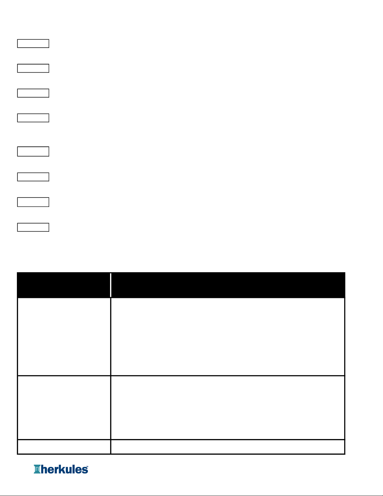
Lift will not go up 1Check that air inlet is connected to the controller.
2 Check to ensure lockout is not engaged (if purchased as option).
3 Check air hoses to ensure no kinks or cuts in the line.
4Check to ensure no debris is preventing wheels from rolling in track.
5 Check regulator gauge is set to minimum of 80 psi (if purchased as option).
Lift is making a hissing noise 1 Check all air lines to ensure they are properly connected and
no leaks are occuring.
2 Check pressure relief valve.
If pressure relief valve is "leaking" lower lift immediately. The air bag
is in a state of over pressurization.
3 Check air bag for cuts or holes.
Lift is making a squeaking noise 1 Lubricate center joints and wheel tracks.
Maintenance Instructions
STEP 1
STEP 6
STEP 2
STEP 3
STEP 4
STEP 5
STEP 8
Possible Solution
Problem
STEP 7
Troubleshooting
Page 10 of 15

ID Part # Description Qty Units
1 12853 Control Valve Assembly - Hand - Lift Only - 2 x Muffler 1 EA
2 12854 Control Assembly - Hand - Lift Only - Wall Mount 1 EA
3 12858 Control Assembly - Hand - Lift Only - Pedestal Mount 1 EA
4 12880 Filter / Regulator Assembly 1 EA
5 12881 Filter / Regulator / Lock Out Assembly 1 EA
6 1002450 Lock Out Valve 1 EA
- 12368 Set of (4) Rubber Blocks - 3-7/8 x 5 x 1-1/2 1 EA
-12371 Set of (4) Rubber Blocks - 4-3/4 x 4 x 3-1/8 1 EA
Optional L1200 Accessories
6
4
5
1
2
3
Page 11 of 15

Part # Quantity Units
10182 RAMP FOR K-900 SGR 8 EA.
10527 WING ASSEMBLY FOR 10526 2 EA.
11177 BOTTOM PAN WLDMT FOR L-1200 1 EA.
11178 INNER SCISSOR WLDMT FOR L-1200 1 EA.
11179 TOP PAN WLDMT FOR L-1200 1 EA.
11182 OUTER SCISSOR L WLDMT FOR L-1200 1 EA.
11183 OUTER SCISSOR R WLDMT FOR L-1200 1 EA.
11185 SAFETY RATCHET WLDMT FOR L-1200 1 EA.
11327 AIR CYLINDER ASSEMBLY FOR L-1200 1 EA.
11328 FOOT CONTROLLER ASSEMBLY FOR L-1200 1 EA.
11585 BOLT HEX 7/8-14 CUT AT 2-3/4 2 EA.
1001205 AIR BAG FOR L-SERIES LIFTS 1 EA.
1001274 HOSE 5/8 ID 250 PSI RUBBER 240 IN.
1001355 BLOCK FOR L-1200 SCISSOR NYLON 6 EA.
1001844 HOSE 1/4 ID 250 PSI RUBBER 216 IN.
1001910 HOSE PROTECTION SLEVE 1/2" 4 IN.
1001911 HOSE PROTECTION SLEEVE 3/4" 12 IN.
1001925 BOLT SHC 8MM-20 X 20MM Z 12 EA.
1001926 BOLT HEX 5/16-18 X 5/8 GD 8 Z 6 EA.
1001927 WASHER BONDED 5/8 ODX5/16 ID SS/NEO 12 EA.
1001928 VALVE PRES RELIEF 3/8 NPT X 55 PSI 1 EA.
1001929 HOSE BARB 5/8 X 3/8 NPT 1 EA.
1001934 NUT JAM LOCK 7/8-14 Z 2 EA.
1001936 PIN 18MM X 45MM HARDENED FOR L-1200 4 EA.
1001937 PIN 18MM X 55MM HARDENED FOR L-1200 2 EA.
1001938 E-CLIP FOR L-1200 6 EA.
1001942 CLAMP HOSE CRIMP TYPE 1 Z 1 EA.
720-122 CLAMP HOSE # 4 SS/Z 1 EA.
810-109-14 CABLE TIE 14 INCH BLACK 18 EA.
84L NUT NYLOCK 5/16-18 Z 6 EA.
Parts List
Description
Page 12 of 15
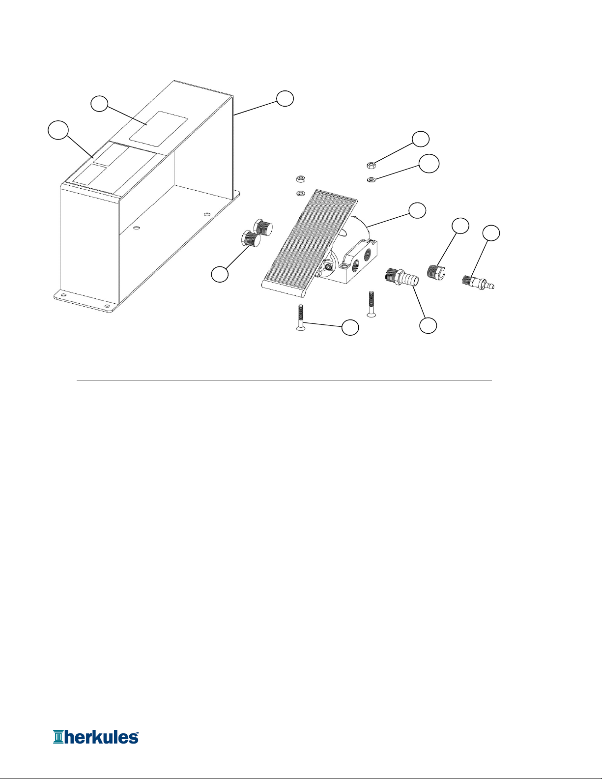
ID Part # Description Qty Units
1 754 VALVE 4-WAY FOOT CONTROL 1/2 NPT 1 EA.
2 1004805 HOSE BARB 1/4 X 1/4 NPT BRASS 1 EA.
3 10071 CNTRL MOUNT WELDM SINGLE FOOT 1 EA.
4 66B RED. BUSHING 1/2 NPT X 1/4NPT BRASS 1 EA.
5 1001393 HOSE BARB 5/8 X 1/2 NPT BRASS 1 EA.
6 1006365 STICKER LIFT UP-DOWN-INDUSTRIAL 1 EA.
7 1001602 VENT BREATHER 1/2 FOR LIFT CONTROLS 2 EA.
8 84 NUT HEX 1/4-20 Z 2 EA.
9 1000996 SCREW FHSC 1/4-20 X 1-3/4 BLACK 2 EA.
10 85 WASHER LOCK 1/4 Z 2 EA.
11 1007741 STICKER RATCHET STOP SAFETY 1 EA.
NOTE: Entire controller assembly is part number 11328
Controller Layout
3
6
8
1
4
2
5
9
7
10
11
Page 13 of 15
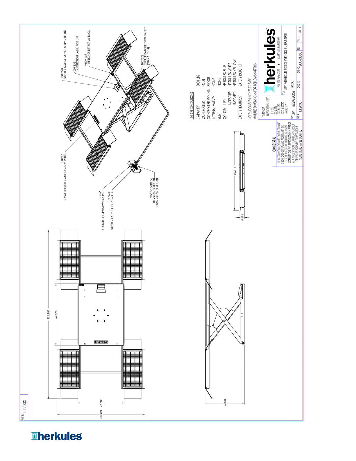
Page 14 of 15
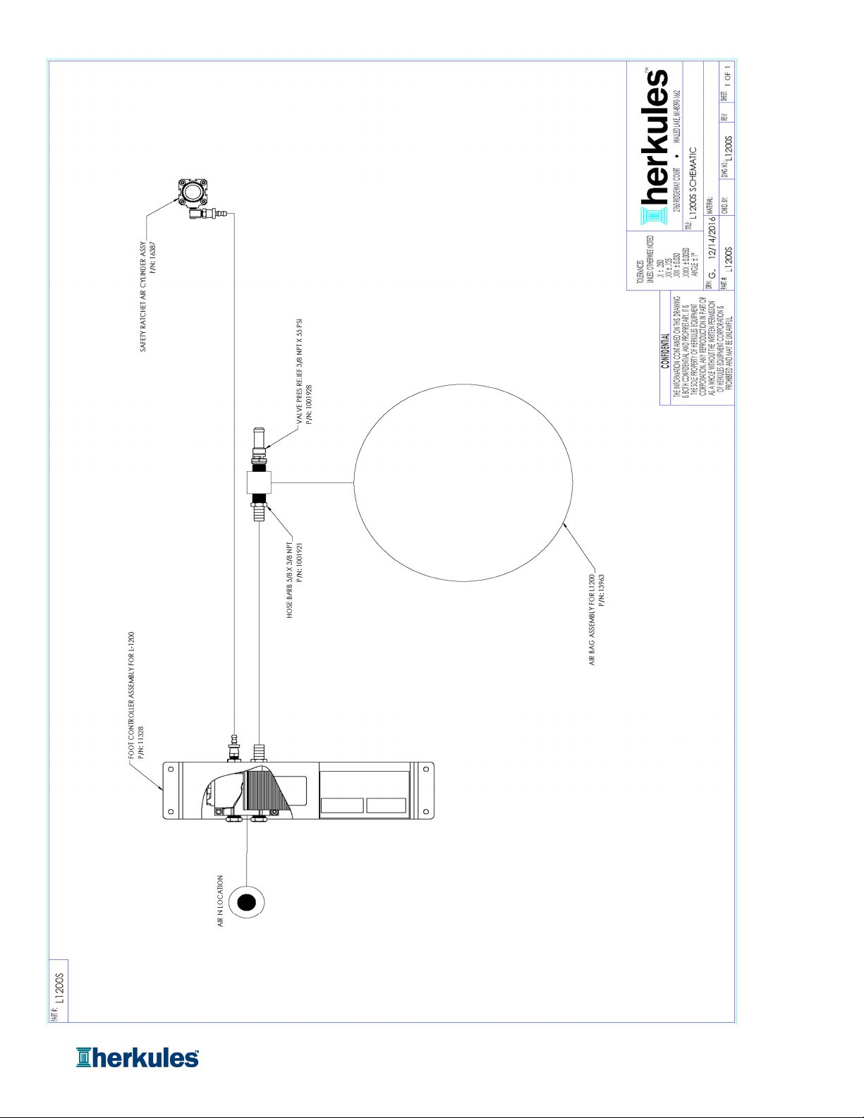
Page 15 of 15
Table of contents
Other HERKULES Lifting System manuals


