Stratus SAE-S66M User manual

Model No. SAE-S66M
Single Post Li
Single (1) Point Manual Release
Liing Capacity 6600lbs
Installaon&Operaon
Maintenance Instrucons
Important Note
1.This equipment can not be installed, operated or repaired without reading instrucons.
2.Electricity must be hooked up by cered electrician.
3.Do not use this equipment beyond its rated capacity.
STRATUS Single Post Li Installaon & Operaon & Maintenance Instrucons

2
Directory
1-Main features of the equipment……………………………………………………………………………………………………………………………………………………3
1.1-Product descripon…………………………………………………………………………………………………………………………………………………………………3
1.2-Features of the product……………………………………………………………………………………………………………………………………………………………3
1.3-Safety Marking of products………………………………………………………………………………………………………………………………………………………3
2-Basic parameters of equipment……………………………………………………………………………………………………………………………………………………4
3-Spare parts in the accessories box…………………………………………………………………………………………………………………………………………………5
4-Shape and size of equipment………………………………………………………………………………………………………………………………………………………5
4.1-Product structure group……………………………………………………………………………………………………………………………………………………………5
4.2-Shape and size of equipment……………………………………………………………………………………………………………………………………………………6
5-Installaon of equipment……………………………………………………………………………………………………………………………………………………………7
5.1-Installaon of columns and bases………………………………………………………………………………………………………………………………………………7
5.2-Installaon of carriage and liing plaorm……………………………………………………………………………………………………………………………………7
5.3-Swing arm lock sha assembly……………………………………………………………………………………………………………………………………………………8
5.4-Arm assembly…………………………………………………………………………………………………………………………………………………………………………8
5.5-Power unit installaon……………………………………………………………………………………………………………………………………………………………9
5.6-Mobil kit installaon………………………………………………………………………………………………………………………………………………………………9
5.7-Wire connecon……………………………………………………………………………………………………………………………………………………………………10
6-Operaon and commission of equipment……………………………………………………………………………………………………………………………………11
6.1-Instrucons for operaon instrucons………………………………………………………………………………………………………………………………………11
6.2-Operaon ow………………………………………………………………………………………………………………………………………………………………………11
7-Maintenance and inspecon of equipment……………………………………………………………………………………………………………………………………12
8-Common trouble shoong…………………………………………………………………………………………………………………………………………………………13
9-Structures and parts list……………………………………………………………………………………………………………………………………………………………14
9.1-Slide carriage exploded view……………………………………………………………………………………………………………………………………………………14
9.2-Loading supporng arm exploded view………………………………………………………………………………………………………………………………………15
9.3-Driven system exploded view…………………………………………………………………………………………………………………………………………………16
9.4-Base assembly………………………………………………………………………………………………………………………………………………………………………17
9.5-Casng front…………………………………………………………………………………………………………………………………………………………………………17
9.6-Swing arm le support arm assembly………………………………………………………………………………………………………………………………………18
9.7-Swing arm right arm assembly…………………………………………………………………………………………………………………………………………………18
9.8-Block assembly……………………………………………………………………………………………………………………………………………………………………19

3
1-Main features of the equipment
1.1-Product descripon
Model: SAE-S66M is a hydraulic li, the whole product can move, with electronic control box, easy to operate. It is
suitable for 6600lbs or less inspecon, repair and maintenance of various types of vehicles.
1.2-Features of the product
The hydraulic li adopts the support arm. Adjustment of the length and width of the outrigger. The li has the charac-
teriscs of compact structure, small space, easy to move, no need to install the base, etc.
1.3-Safety Marking of products
Do not operate the li unless you read and understand the operaon manual.
Don’t stand under the vehicle or on the li.
No stacking of debris,Always keep li area clear,when lowering or raising vehicle.
Do not li one side of the vehicle.
Only Authorized person can be in the li area.
Do not place feet under any part of the li while lowering.
1.Rise 2.Stop.
Always use safety stands when moving / installing heavy components.
Digest of safety operang li
*The operaon of the li is permied by authorized persons only.
*It is necessary to refer to the complete operaon instrucons, especially for trouble shoong.
*Movable and mobile lis shall be prevented from moving unintenonally.
*The eld of moon of the load and of the load carrying devices shall be free of obstrucons.
*It shall draw aenon to the safe method of carrying the load and to the rule that, aer raising a short distance,
the vehicle shall be checked to ensure that it is correctly and safely posioned.
*It shall draw aenon to the rule that the load carrying device shall be observed by the operator throughout the
moon of the li.
*It is forbidden for people to stand in the eld of moon of the load and the load carrying device during the move-
ment.
*It is forbidden to climb onto the load or load carrying device when they are raised.

4
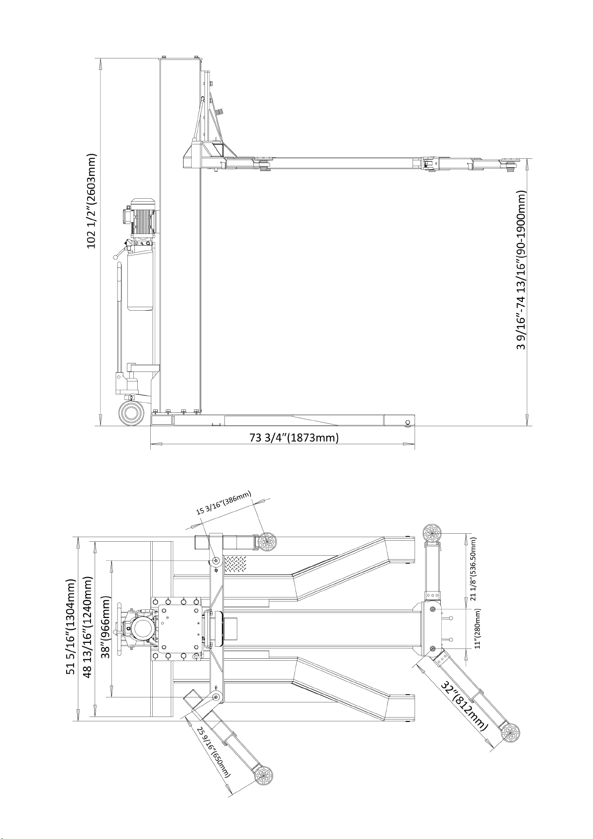
2-Basic parameters of equipment
Model SAE-S66M
Liing capacity 6600lbs(3000Kg)
Max liing height 74 13/16″(1900mm)
Min height 3 9/16″(90mm)
Liing me About 50 Sec.
Lowering me About 40 Sec.
Column Thickness of Steel 5.5mm
Carriage Thickness of Steel 12mm/20mm
Arms Thickness of Steel 6mm
Arm range 15 3/16"-25 9/16"(386-650mm)
21 1/8"-32"(536.5-812mm)
Motor voltage 110V/220V
Motor Power 3 HP
Rated Frequency 60Hz
Breaker 30A
Hydraulic oil 3-5 Gallons AW32/AW46
Shipping Size 114″×59″×34″
Shipping Weight 2119lbs
4-Shape and size of equipment
4.1-Product Structure Group
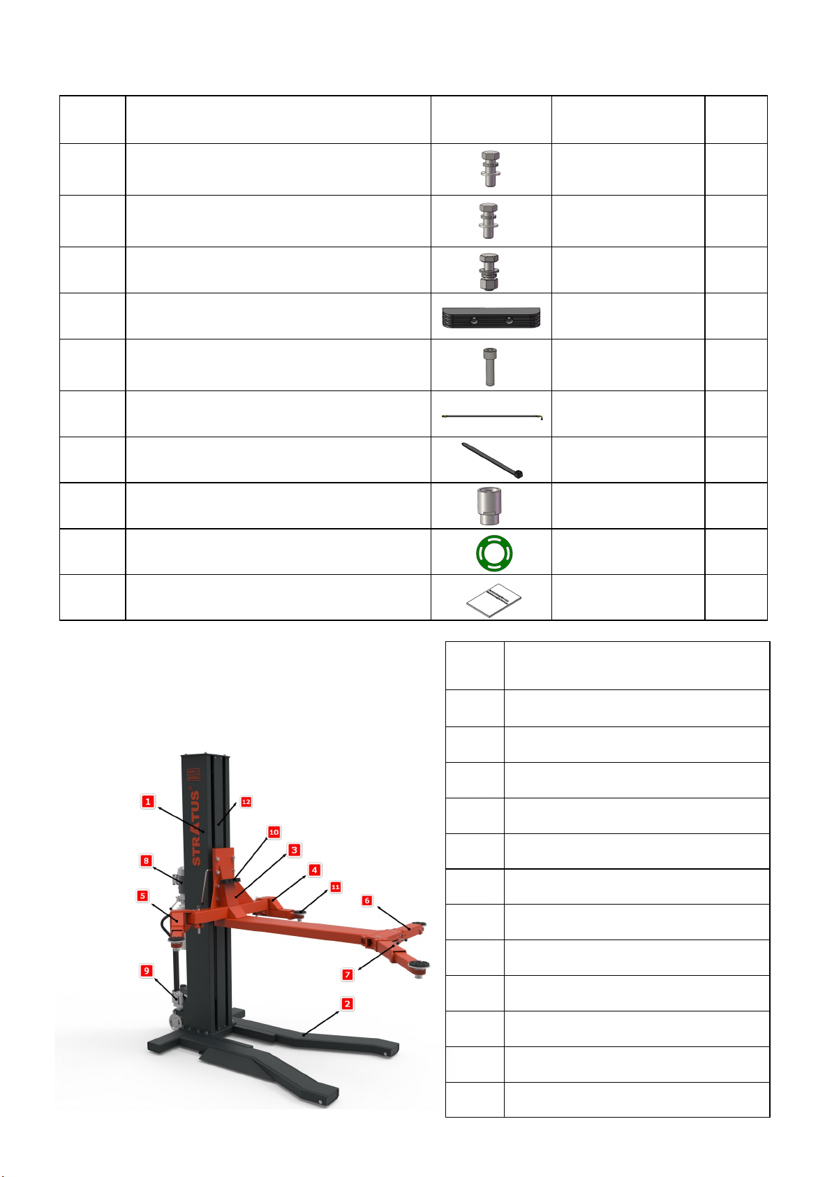
3-Spare parts in the accessories box.
Serial
number Name Photo Parameter Quanty
1Swing arm big support arm combinaon and
block assembly connecon screw Hexagon Screw 8
2Column and base connecng screw Hexagon Screw 10
3Power unit xing screws Hexagon Screw M8×25 4
4An-collision tape 1
5Heightening sleeve bracket xing screw Hexagon socket screws 2
6Hose 1
7Plasc cable e 30
8Increased set Φ55×70L 4
9Round gasket 2
10 User’s manual 1
Serial
number Name
1Column assembly
2Base assembly
3Swing arm big support arm assembly
4Right swing arm assembly
5Le swing arm assembly
6Le front arm assembly
7Right front arm assembly
8Hydraulic power unit
9Press handle trolley assembly
10 An-collision tape
11 Screw base
12 Pillar curtain
6
4.2-Shape and size of equipment

7
5-Installaon of equipment
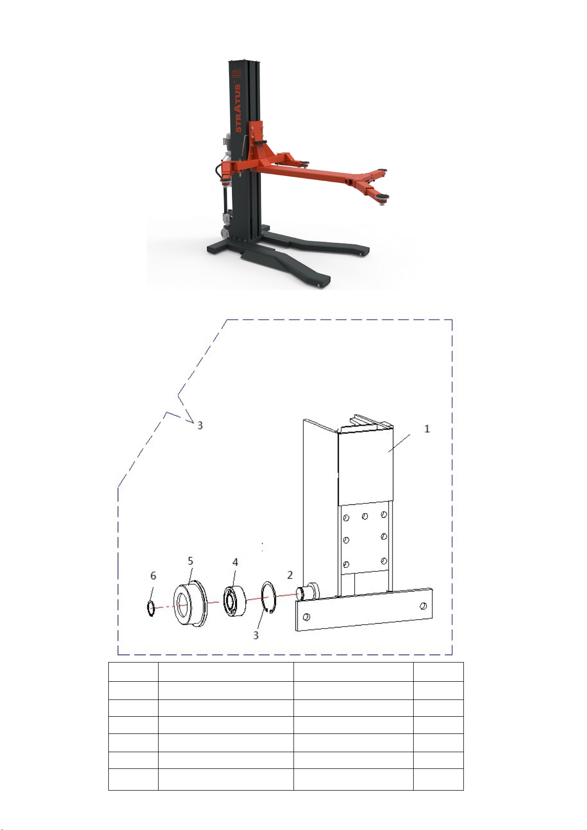
5.1-Installaon of columns and bases
5.2-Installaon of carriage and liing plaorm
1.Base
2. Column
3. Flat pad Φ20
4. Spring mat Φ20
5.Hexagon bolt M20×50
1. Carriage
2. Liing plaorm
3. Hexagon bolt M18×50
4. Spring mat Φ18
5. Flat pad Φ18
6. Rubber
7.Hexagon bolt M8×30

8
5.3-Swing arm lock sha assembly
1.Swing arm lock sha liing ring
2.CirclipΦ16
3.Small square lock spring
4.Swing arm lock sha
5.Small square lock tooth
6.Swing arm lock small sha
5.4-Arm assembly
1.Right swing arm welding
2.Le side swing arm welding
3.Front support has welding
4.Swing arm rear axle welding
5.Front arm sha welding
6.Flat head hexagon socket screwM8×10
7.Round gasket
8.Grease cup

9
5.5-Power unit installaon
5.6-Mobil kit installaon
1.Column assembly
2. Power unit
3. Hose
4.Hexagon screw M8×30
5. Spring cushionΦ8
6.Flat padΦ8
7.Hex nuts M8
1. Hydraulic liing assembly
2. Hydraulic liing sha
3. Axle clip spring Φ25

10
5.7-Wir connecon
**Important Informaon**
Pressure Valve: Clockwise adjustment increases pressure to make the power unit to have more power,
counterclockwise adjustment decreases pressure to make the power unit to have less power.
Hydraulic Oil ow valve: Clockwise adjustment to speed up, counterclockwise adjustment to slow down.

11
6-Operaon and commission of equipment
6.1-Instrucons for operang
6.1.1 Check all joints and tubing connecons. The machine can only be used if there is no oil leak.
6.1.2 If the safety device of the li fails, it must not be put into use.
6.1.3 If the center of gravity of the repaired vehicle is not located in the center of li range, Anybody can not operate
the li, otherwise the manufacturer and dealers do not bear any consequences.
6.1.4 The operator and other sta must stand in a safe area during the li’s ascent and descent.
6.1.5 When the arm is raised to the required height, the power must be turned o to avoid misoperaon by non-
operators.
6.1.6 Make sure the safety lock is in bite posion before working under the car. All personnel shall not be under the
vehicle while the li is going up and down.
6.2-Operaon Flow
To avoid damage to personal property, only trained personnel can operate the li. Before liing the vehicle, read the
operaon instrucon and teat operaon of the li to be familiar with the control of the li. Always use four liing pal-
lets to li the vehicle. Do not li only one end or end of the vehicle.
6.2.1-Li Up
1.The vehicle sops, moves the lier, moves the lier under the vehicle; or the lier does not move, the moving vehicle
passes the lier and stops to the proper posion.
2. Swing the liing arm to the car’s center of gravity is at the center of the four liing arms.
3. To turn on the power switch, gently press the up buon on the power unit unl the liing arm pad touches the sup-
port point of the car.
4. Keep going up, get the car o the ground a lile bit, and then check the car’s posion again.
5. Rise to the required height, check whether the car is safe, and then press the lock buon on the electronic control
box so that the safety lock in place, then workers can work under the car.
6.2.2-Lier down
1. Make sure there are no people or other obstacles under the car before you descend.
2. Open the power switch, press the drop buon on the power unit the machine will automacally rise about 5cm, out
of the safety, electromagnet work, li down.
3. Aer the liing arm is completely lowered, the mobile liing arm leaves the car or the retractable arm drives the car
away.

12
7-Maintenance and inspecon of equipment
No. Item Method Period
1Arm Safety lock Gear
Assembly Manually check arm safety lock teeth for occlusion and complete lock. Everyday
2Spiral base Check the li arm, clean and replace the rubber base. Everyday
3Oil Cylinder and Oil
pipe joint Before using the li, check for oil leakage Everyday
4Safety lock combina-
on
Check that the safety lock can be unlocked and unlocked synchronous-
ly. Everyday
5Limit Switch Press the up buon, when the gear limit is in eect, whether the liing
stops the up movement. Everyday
6Power unit Inspect unloading valve for leakage. If leakage occurs, clean or replace
the unloading valve. Everyday
7Slide track Lubricate the chain with N0.1 lithium based grease. No obstrucon on
the track. Every three month
8Chain and pin Lubricate the chain with N0.1 lithium based grease. Every three month
9Wholeness The amount of load or no-load lier several back and forth, lier
should run stable sound. Every three month
10 Hydraulic oil Replace Hydraulic Oil 6 months aer rst use and annually thereaer.
Check the cleanliness of the hydraulic oil, if the hydraulic oil blackened Every year

13
8-Common trouble shoong
Troubles Reason Soluon
Find out unusual sound
Any fricon marks on the inside of the cylin-
der Grease the inside of the column.
If there’s an obstrucon in the cylinder Clear the obstacle.
The Motor doesn’t turn, it
doesn't go up
Bad wire contact Check and connect the lines.
Motor broken and burnt out Replace Motor.
The limit switch is damaged Replace limit switch.
The motor turns but does not
rise
Motor reversal Correcve wiring.
Loose relief valve or obstrucon Adjust or clean the relief valve.
Gear pump damage Replacement gear pump.
The sucon pipe came loose and fell o Tighten the sucon pipe.
The lter screen of the oil sucon pipe is
blocked Clean the lter screen.
Take it down slowly as it rises
Check the tubing for leakage Replace tubing.
Poor cylinder seal Replace cylinder seal.
Poor sealing of check valve Clean up or replace.
Poor Relief Valve Clean up or replace.
Poor electromagnec relief valve Clean up or replace.
Slow ascent
Plugging of oil lter Clean up or replace.
Oil pressure mixed with air Replenishing hydraulic oil.
The overow valve is not adjusted properly Readjusng
Heang of hydraulic oil(above45°) Change hydraulic oil
Cylinder seal wear out Replaceseals
The drop throle is jammed with an obstruc-
on Clean up or replace
Slow descent
Hydraulic oil is dirty Change hydraulic oil
There is an obstrucon in the explosion-proof
throle
Replacement of explosion-proof
throle valve
There’s a blockage in the oil pipe Clean up or replace
14
9. Structures and parts list
9.1 Slide carriage exploded view
No. Name Specicaons Qty.
1Weld carriage assemble 1
2Inner hex column bolt GB/T70.1-2000 M6x16 1
3Column roller bearing GB/T283-94 NUP2308M 2
4Slide wheel 2
5A- type sha keep o ring GB/T894.1-1986 40 2
6A- type bore keep o ring GB893.1-8390 2
15
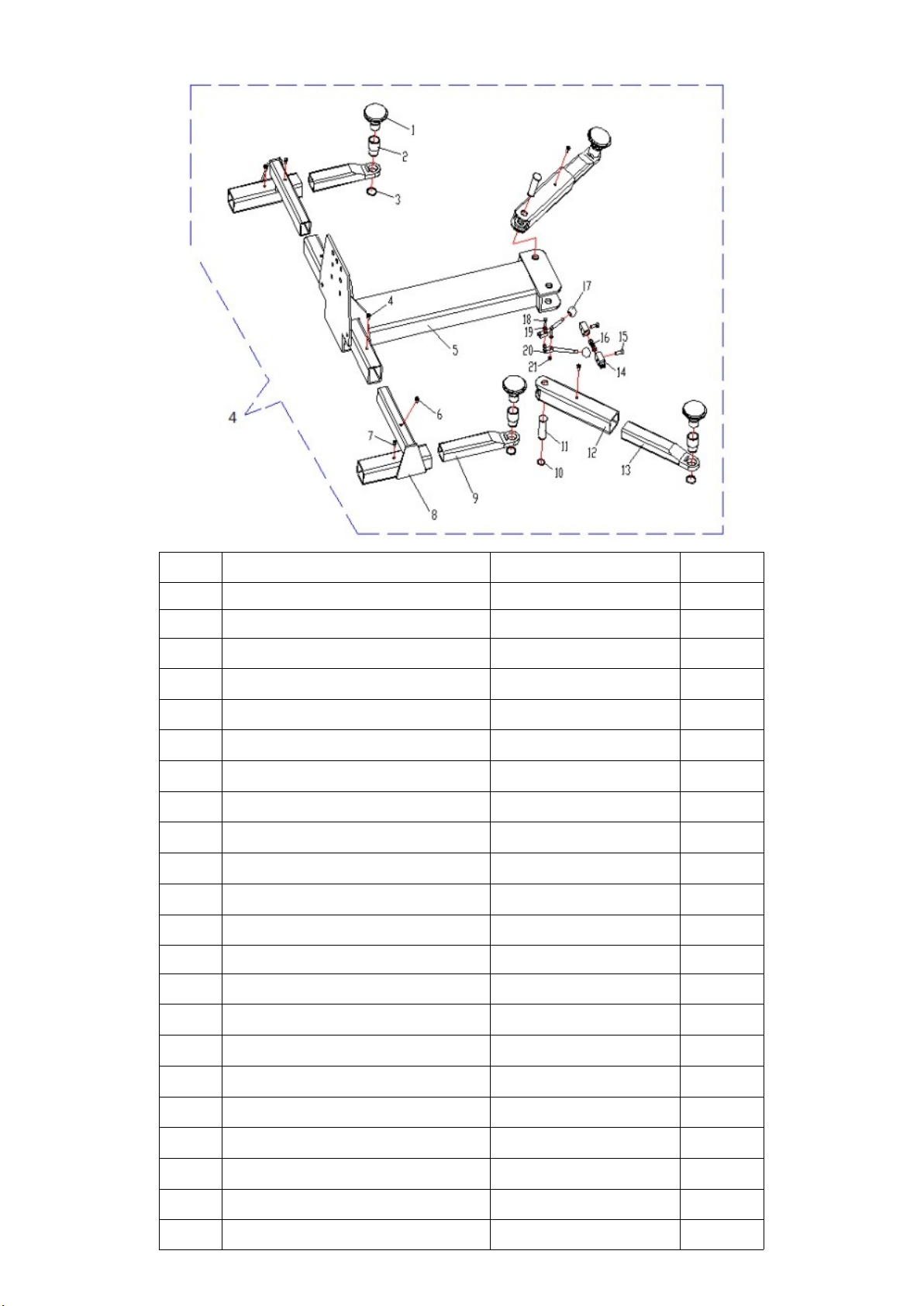
9.2 Loading supporng arm exploded view
No. Name Specicaons Qty.
1Three group screw plate φ50 4
2Height set 4
3A-type sha keep o ring GB/T894.1-1986 50 4
4Cross tray bolt GB/T 818-2000 M6X12 4
5Main supporng beam 1
6Inner hex column bolt GB/T70.1-2000 M6x12 2
7Cross tray bolt GB/T 818-2000 M6X12 2
8Rear weld assemble 2
9Rear extendable arm assembly 2
10 A-type spring keep o ring GB/T894.1-198636 2
11 Arm x sha 2
12 Arm assemble 2
13 Front extendable arm assembly 2
14 Slide gear tooth 2
15 Inner hex column bolt GB/T70.1-2000 M6x16 2
16 Spring 1
17 Handle ball M10 2
18 Hex bolt GB/T5781-2000 M8x35 2
19 Flat washer GB/T97.1-1985 8 2
20 Lock release fork assemble 2
21 Non metal embedded ghten nut GB/T 6172.2-2000 2
22 Supporng arm assembly 1

16
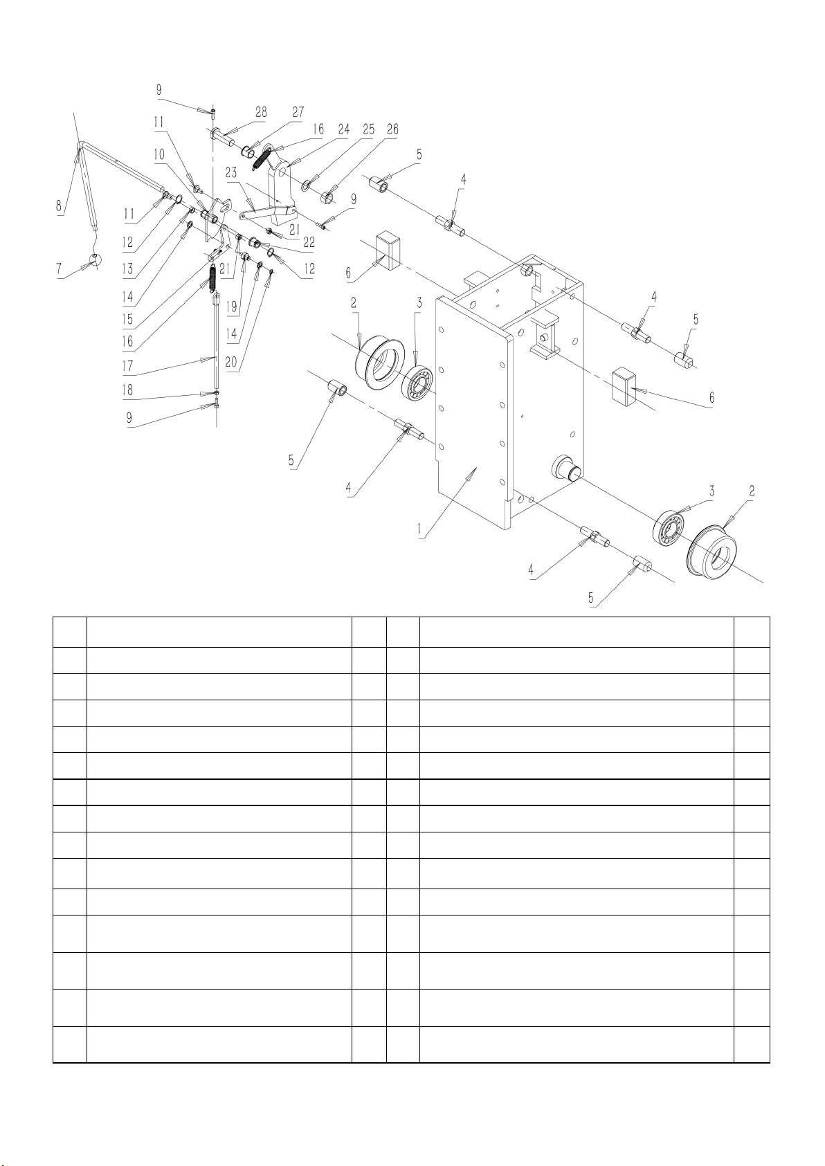
9.3-Driven system exploded view
No. Name Qty.
1Pipe connecng 1
2Cylinder 1
3Cylinder cover 1
4Cylinder guide 1
5Dust proof ring 1
6Rod 1
7Y- type seal ring 1
8Guide ring 1
9O - type ring 1
10 Rod 1
11 Trolley base 1
12 Chain wheel 1
13 Spring washer 1
14 Cross tray bolt 1
15 Welded wheel sha 1
16 Non oil bearing 1
17 Plate chain 1
18 Placket pin 4
19 Chain connecng sha 1
20 Placket pin 1
21 I - type hex nut 2
22 Drive system 1

17
No. Name Qty.
1Base welding 1
2Base roller sha 2
3Base roller 2
4Oil-free bearing 4
5Circlip 4
9.4-Base assembly
No. Name Qty.
1Cast front support arm 1
2Mobile arm welding 1
3Oil-free bearing 1
4Casng front arm crescent teeth 1
5Socket head cap screws M10×20 3
6Flat head hexagon socket screw M8×20 1
7Rubber pad 1
8Pallet welding 1
9Tray adjustment sleeve 1 1
10 Socket head cap screws 1
11 Tray adjustment sleeve 2 1
12 Socket head cap screws M10×12 1
9.5-Casng front arm assembly

18
No. Name Qty.
1Welding of le arm of swing arm 1
2Mobile arm welding 1
3Swing arm moon teeth 1
4Flat pad Φ10 3
5Spring cushion Φ10 3
6Hex bolts M10×35 3
7Socket head cap screws M10×12 1
8Flat head hexagon socket screw
M8×20 1
9Rubber pad 1
10 Pallet welding 1
11 Tray adjustment sleeve 1 1
12 Tray adjustment sleeve 2 1
13 Socket head cap screws M8×18 1
No. Name Qty.
1Welding of le arm of swing arm 1
2Swing arm welding 1
3Swing arm moon teeth 1
4Flat pad Φ10 3
5Spring cushion Φ10 3
6Hex bolts M10×35 3
7Socket head cap screws M10×12 1
8Flat head hexagon socket screw
M8×20 1
9Rubber pad 1
10 Pallet welding 1
11 Tray adjustment sleeve 1 1
12 Tray adjustment sleeve 2 1
13 Socket head cap screws M8×18 1
9.6-Swing arm le support arm assembly
9.7-Swing arm right arm assembly
19
No.Name Qty. No.Name Qty.
1Manual lock trolley welding 115 Welding of manual lock card wheel support plate 1
2Sha bowl 216 Manually unlock the tension spring 2
3Bearing-NU308E 217 Manual lock wheel connecng rod welding 1
4Nylon bushings on both sides of the trolley 418 Hex nuts M6 1
5Nylon sleeve 419 Manually unlock the card wheel support plate sha 1
6Nylon slider 220 Circlip Φ10 1
7Handball 121 Self-locking hexagon nuts M8 2
8Manual unlocking lever 122 Manual unlocking lever plus sleeve 1
9Socket head cap screws M6×20 323 Manual lock connecng plate 1
10 Manual lock fork welding 124 Lock plate welding 1
11 Manually unlock the sliding sleeve 225 Lock plate septa 1
12 Circlip Φ20 226 Hexagon nut M18 1
13 Manually unlock the sliding sleeve 127 Manual lock plate cover 1
14 Flat pad Φ10 128 Lock plate sha 1
9.8-Block assembly

20
Table of contents
Other Stratus Lifting System manuals

Stratus
Stratus SAE-UT9000 Guide

Stratus
Stratus SAE-C9P Guide

Stratus
Stratus SAE-P48 Guide

Stratus
Stratus SAE-C12X Guide

Stratus
Stratus SAE-C10C Guide

Stratus
Stratus MS9000XT User manual

Stratus
Stratus SAE-F10S Installation instructions

Stratus
Stratus SAE-C10P Guide

Stratus
Stratus SAE-F12X Guide

Stratus
Stratus SAE-P166M Guide


Popular Lifting System manuals by other brands

Arjo
Arjo Tenor Instructions for use

Hinowa
Hinowa GOLDLIFT 14.70 Manual use and maintenance

Sunrise Medical
Sunrise Medical Oxford/Hoyer Stature User instruction manual & warranty

morse
morse 515-N-110 Operator's manual

Nibotechnics
Nibotechnics Autolift electric installation instructions

Terrier
Terrier TTL owner's manual


