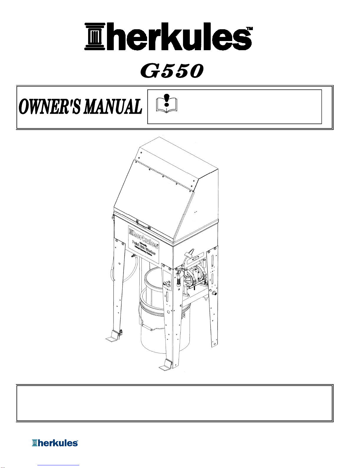
HERKULES G550 User manual
Part# 1003108-08
3/29/2010
This manual contains important information concerning the
installation and operation of the gun washers listed above.
Read manual thoroughly and keep for future reference
INSTRUCTIONS
This manual contains important information concerning the
installation and operation of the gun washers listed above.
Read manual thoroughly and keep for future reference
INSTRUCTIONS
Herkules Equipment Corporation 2760 Ridgeway Court Walled Lake, MI 48390-1662 USA
248-960-7100 800-444-4351 Fax 248 960-7109
Patents USA 7070167 4793369, 4960142, 5174317, 5193561, 5485860 Canada 1299468 & Patents Pending
website: www.herkules.us Made in the USA e-mail: info@herkules.us
Page 1 of 12
Warnings ……………………………………………………………………………………………………………………… 3-4
Model Information ……………………………………………………………………………………………………………. 5
Installation ………………………………………………………………………………………………………………….. 5
Operation ……………………………………………………………………………………………………………………. 6-7
Preventive Maintenance ………………………………………………………………………………………………………. 7
Troubleshooting ……………………………………………………………………………………………………………… 8
Drawings with part lists: …………………………………………………………………………………………………… 9-12
Table of Contents
Warning Symbol Caution Symbol
Page 2 of 12
Serial Number
Model Number
Purchase Date
Distributor
CAUTION
WARNING
This symbol alerts you to the possibility of serious
injury or death if you do not follow the instructions. This symbol alerts you to the possibility of damage to
or destruction of equipment if you do not follow the
instructions.
This product has patent protection under
one or more of the following patent numbers:
7070167, 5485860, 5193561, 5174317
4960142, 4793369, 1299468
and Patents Pending
website: www.herkules.us 1002742
PATENT NUMBERS
Page 2 of 12
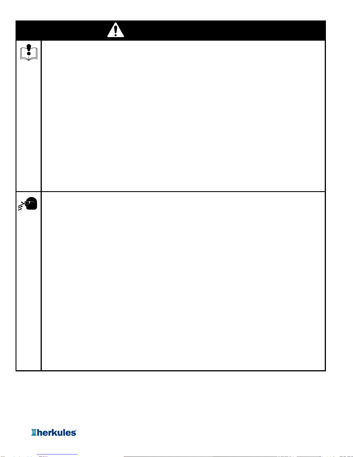
EQUIPMENT MISUSE HAZARD
Equipment misuse can cause the equipment to rupture, malfunction, or start unexpectedly
and result in serious injury.
•This equipment is for professional use only.
•Read all instruction manuals, tags, and labels before operating the equipment.
•Use the equipment only for its intended use.
•Do not alter or modify this equipment.
•Do not exceed the maximum working pressure of the lowest rated system component.
•Do not operate the gun washer at a pressure above the maximum working pressure rating of the
gun(s) being cleaned.
•Route the hoses away from traffic areas, sharp edges, moving parts, and hot surfaces.
•Do not use the hoses to pull the equipment.
•Do not move pressurized equipment.
•Comply with all applicable local, state and national fire, electrical and other safety regulation.
PRESSURIZED EQUIPMENT HAZARD
Spray from hose leaks, ruptured components, or from operating the gun washer with an open lid
can splash fluid in the eyes or on the skin and cause serious injury.
WARNING
Page 3 of 12
•Do not stop or deflect fluid leaks with your hand, body, glove, or rag.
•Tighten all fluid connections before operating the equipment.
•Replace worn, damaged, or loose parts immediately.
WARNING
Page 3 of 12
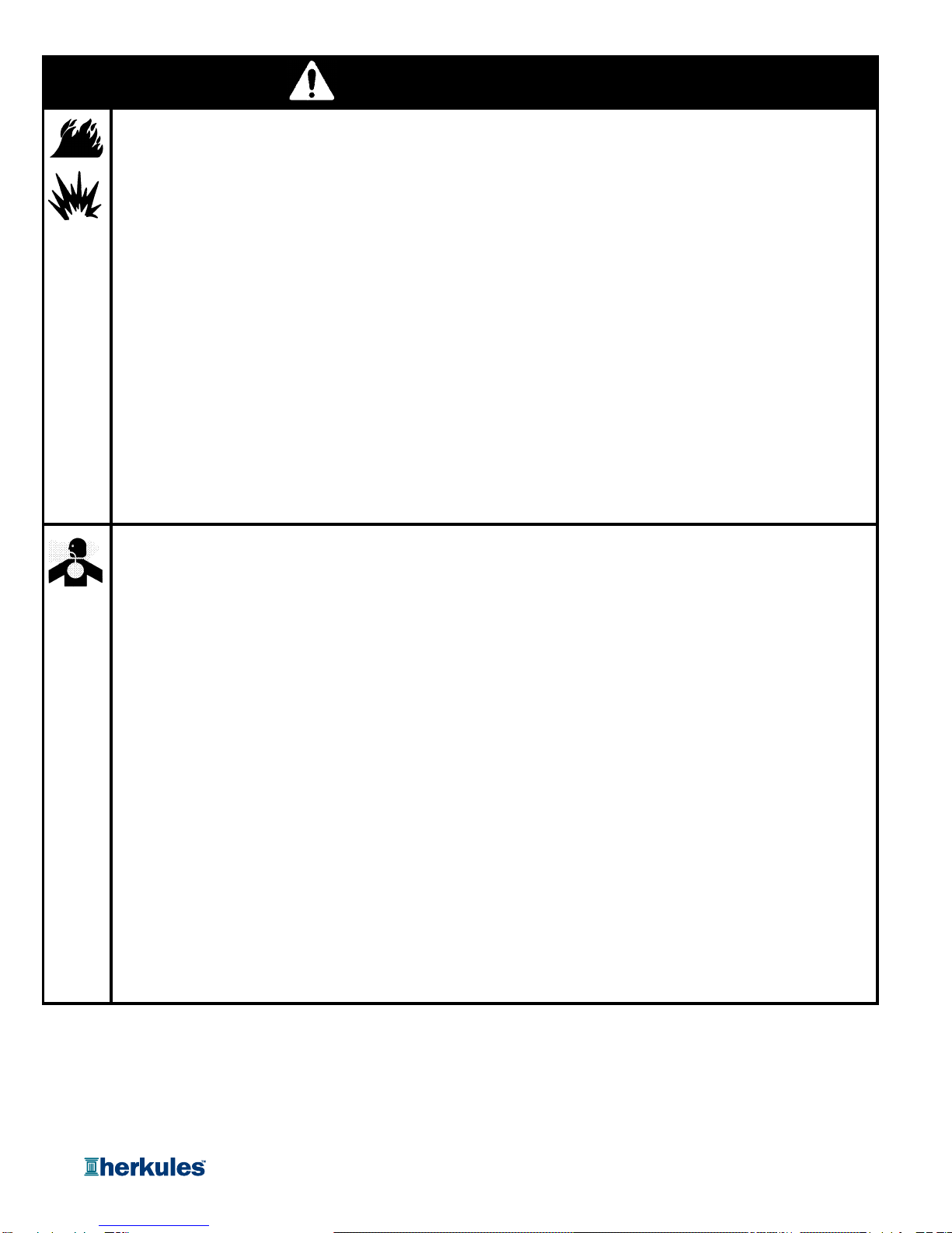
FIRE AND EXPLOSION HAZARD
Improper grounding, poor air ventilation, open flames, or sparks can cause a hazardous condition
and result in fire or explosion and serious injury.
•Ground the equipment. See Installation for grounding procedure.
•Provide fresh air ventilation to avoid the build up of fumes.
•Extinguish all open flames or pilot lights in the gun washer area.
•Disconnect all electrical equipment in the gun washer area.
•Keep the gun washer area free of debris, including cleaning solutions, rags, and gasoline.
•Do not turn on any light switch in the gun washer area while operating or if fumes are present.
•Do not smoke in the gun washer area.
•Do not operate a gasoline engine in the gun washer area.
•If there is any static sparking while using the equipment, stop operation immediately. Identify and
correct the problem.
TOXIC FLUID HAZARD
Hazardous fluids or toxic fumes can cause serious injury or death if splashed in eyes or on the
s
kin
,
s
w
a
ll
o
w
ed,
o
r inh
a
l
ed
.
WARNING
Page 4 of 12
skin
,
swallowed
,
or
inhaled
.
•Know the specific hazards of the fluid you are using. Read the fluid manufacturer's warnings.
•Store hazardous fluid in an approved container. Dispose of hazardous fluid according to all local, state
and national guidelines.
•Wear the appropriate protective clothing, gloves, eyewear and respirator.
•Pipe and dispose of the exhaust air safely. If diaphragm fails, the fluid may be exhausted along with
the air.
WARNING
Page 4 of 12

Model Information
Dimensions in./(mm)
A
BCD
Manual cleaning waterborne Gun Washer includes 56 15.5 6.5 20.38
pressure cleaning nozzle, clean rinse nozzle, flow thru (1422) (394) (165) (518)
bhditt/ lt
NOTE: Dimensions listed are overall measurements.
G550
Model
69
(31.3)
Weight
lbs/(kg)
Description
A
B
C
D
brush and agitator / accelerator.
Installing the Gun Washe
r
1) Place gun washer on a level surface in a properly
ventilated paint mixing room or paint booth.
Grounding the Gun Washe
r
1) Connect the ground wire on the gun washer’s pump to a
true earth ground.
2) Ground all equipment used or located in the gun washer
area.
Connecting the Air Line
1) Install a 1/4 in. npt male coupler, that is compatible with
the quick disconnect of your air supply line, into the air
supply port of the filter/regulator located on the back right
leg.
2) Connect air line with at least 75 psi to the coupler.
Filter/regulator is preset. Do not adjust.
Installation
A
B
C
D
Air supply
port
Page 5 of 12
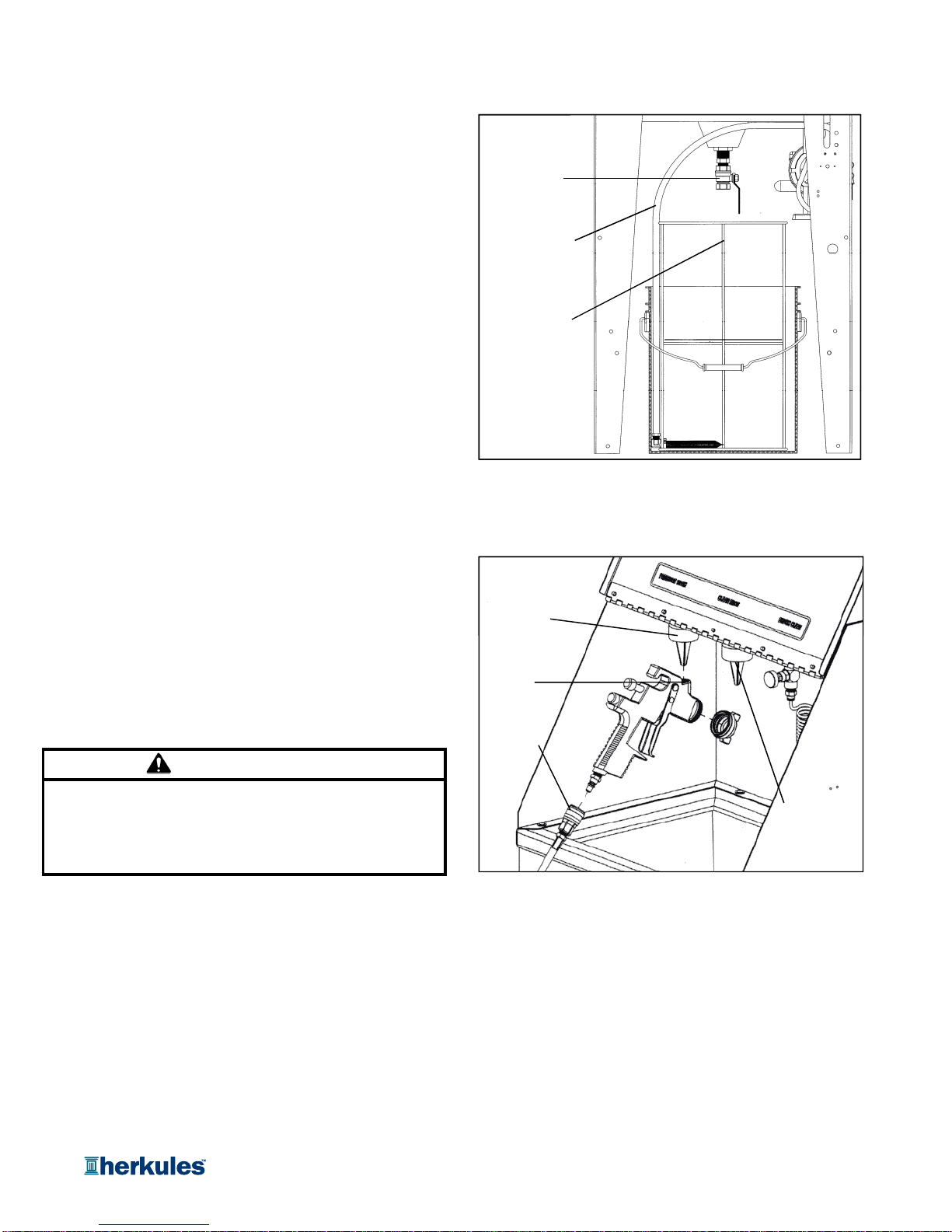
Connecting the water to the washe
r
1) Insert the filter mount frame into the bucket.
2) Fill with water until the water level reaches the bottom
of the filter support cross arms.
3) Connect the large filter bag to the filter mount frame so
that the bottom of the filter is resting on the filter
support.
4) Insert the small filter bag into the large bag and
connect to the filter mount frame.
5) Place the bucket under the Gun Washer and insert the
pick up tube between the bucket wall and the filter.
6) Close ball valve.
Preparing the Equipment to be washed
1) Remove paint cup or paint line and the air line from the
paint gun.
2) Drain excess paint from cup and gun into a separate container.
3) Remove all gauges and regulators from painting equipment.
4
)
Remove the air ca
p
/fluid ti
p
from the
p
aint
g
un.
Operation
Filter mount frame
Ball valve
Pick up tube
Pressure
clean nozzle
4)
Remove
the
air
cap/fluid
tip
from
the
paint
gun
.
5) Connect the air channel line to the spray gun using the
supplied quick disconnects or replace the supplied quick
disconnects with ones compatible with the shops equipment.
CAUTION
All pressure gauges must be removed before placing the
equipment in the gun washer to avoid damaging the
gauges.
Cleaning Equipmen
t
4) Squeeze the trigger of the spray gun and step on the
pressure clean / brush clean foot pedal to send a
1) Set the indicator on the front leg to cleaning brush. Press the pressurized flow of water through the paint channel.
foot pedal located at the bottom of the front leg to activate the
cleaning brush. Manually clean the paint cup (if present), Note: Position the spray gun so that the flow of water
the removed air cap assembly and the outside of the paint exiting the paint gun is contained within the Gun Washer
gun. tub.
2) Set the indicator on the front leg to pressure clean.
3) Position the spray gun so the pressure clean nozzle is
inserted into the paint channel of the spray gun.
Filter mount frame
Ball valve
Pick up tube
Paint
channel
Pressure
clean nozzle
Clean rinse
nozzle
Air channel
line
Page 6 of 12

Clean rinse Filtering Dirty water (optional)
1) Fill an additional bucket (not supplied) with clean water. 1) Remove the cleaning platform from inside of the tank.
2) Insert the clean rinse pick up tube located on the left side 2) Add flocculant (not supplied) to the dirty water.
of the Gun Washer in the bucket. Note: Contact local distributor to purchase flocculant.
3) Set the rinse / agitator switch on the right side of the Gun Amount of flocculant required and time required will vary
Washer to rinse. depending on the brand flocculant being used.
4) Position the spray gun so the clean rinse nozzle is 3) Start the agitator by setting the rinse / agitator switch to
inserted into the paint channel of the spray gun. agitator. Allow the dirty water / flocculant mix to agitate
for 30 to 120 seconds (dependent upon quality of
5) Squeeze the trigger of the spray gun and step on the flocclant). Stir the water for 30 seconds during agitation.
clean rinse foot pedal to send a pressurized flow of Let the water sit for 30 seconds. Return the rinse /
clean water through the paint channel. agitator switch to the neutral position.
6) Return the rinse / agitator switch to the neutral position Note: Repeat process if adequate seperation does not
when finished. occur (dependent upon quality of flocculant).
7) Use the air gun to dry off any wet components. 4) Open the ball valve to allow the dirty water to drain
through the filter bags. The filter bags capture the
Disposal paint debris, and the bucket captures the filtered water
that can be reused for cleaning.
1) Once all the water has been pumped out of the bucket
you have two options. Note: Reuse the water until it becomes tacky to the
touch then dispose of the dirty water according to
a. Remove the filters from the bucket, open the ball local, state and national regulations.
valve to allow the dirty water to return to the
Operation
Page 7 of 12
valve
to
allow
the
dirty
water
to
return
to
the
bucket without filtering. Reuse the water until it 5) Clean the inside of the tub using the cleaning brush.
becomes tacky to the touch then dispose of the Once the tub is clean, use the pressure clean nozzle
dirty water according to local, state and national to clean off the brush.
regulations. 6) Clean the filter bag by removing the paint debris.
b. Filter the water using a flocculant (not supplied)
and the filter bag supplied with the Gun Washer. Note: Allow the flocculated paint to dry before removing
from filter.
7) Dispose of all paint waste according to local, state
and national regulations.
8) Close the ball valve and return the cleaning platform
to the inside of the tub. Replace filter bags (1003348
& 1003351) as needed.
Page 7 of 12

1) Drain excess paint from cup or pot before placing in gun
washer.
2) Remove the filter bowl and check the filter inside the
regulator for excess buildup approx. every 6 months.
3) Change water completely when objects being cleaned
become tacky to the touch.
4) Clean inside of tub.
Do not change the setting of the filter/regulator. This
could damage the filter/regulator or pump.
Troubleshooting
Pump turns on but wash water 1Make sure wash bucket is not empty.
does not flow. 2Make sure the filter at the end of the pick up tube is completely submerged
in water
Possible Solution
Preventive Maintenance
CAUTION
Problem
Filter/Regulator
#T17M
Filter Bowl
Filter
#1001382
Page 8 of 12
in
water
.
3 Check all fluid connections to ensure that there are no leaks.
4 Make sure the indicator on the front leg is set to pressurized clean.
Pump does not turn on. 1 Make sure intake filter is not clogged (Clean or replace).
2 Make sure the air line is properly connected with at least 75 psi.
Air pressure is regulated at 75 psi.
3 Check all air connections to ensure that there are no leaks.
4 Make sure foot pedal valve is functioning correctly.
No flow through the manual brush. 1 Make sure wash bucket is not empty.
2Make sure the filter at the end of the pick up tube is completely submerged
in water.
3 Check all fluid connections to ensure that there are no leaks.
4 Make sure the indicator on the front leg is set to brush clean.
Page 8 of 12

G550 Parts Layout
10 20
17
26
38
40
13
19
42
14
29
22
28
27
4
23
37
24
39
31
21
30
33
32
34
35
46 44
Page 9 of 12
10 20
17
26
38
40
13
19
42
14
29
22
28
12
27
18
2
1
4
23
37
15
45
11
6
16 7
25
36
41
24
39
43
9
31
21
8
30
33
32
34
35
46
3
44
Page 9 of 12

Part
#
Description
16 Ball Valve 1 EA
262 Reducer 1/2 NPT X 3/8 NPT 1 EA
385 Lock Washer 1/4 5 EA
4T4 Hose Fitting 5/32 X 1/8 NPT 1 EA
513044 Pump Bracket 1 EA
613045 Pump Assembly 1 EA See pg. 11
713047 Leg Assembly with Regulator 1 EA See pg. 11
8318 Rinse Pump 1 EA
913053 Filter Assembly 1 EA
10 13107 Shroud assembly 1 EA
11 13109 Leg Assembly with Valve 1 EA See pg. 11
12 13117 Leg Assembly with Rinse control 1 EA
13 1001569 Screw HHMS 10-32 x 1/2 SS Type F 2 EA
14 1000563 Brush 1 EA
15 1001119 Hook Bolt 1/4-20 1 EA
16 1002378 Leg 1 EA
17 1002643 Bulkhead 3/4 - Brass 3 EA
18 1002644 Bulkhead 1 - Brass 1 EA
19 1003597 Rivet 1/4 x 1/2 Aluminum Blind 15 EA
20 1002779 Elbow 1/4 NPT 3 EA
21 1002795 Stand Frame 1 EA
22 13901 Cleaning Platform 1 EA
23 1002912 Toggle valve 1 EA
24 13800 Air Gun 1 EA
25 1002914 Bucket 1 EA
26 T25 Hose Fitting 90° 5/32 x 1/4 NPT 1 EA
27
1002953
Spring Clip 7/8 X 1
-
1/8 SS
1
EA
Quantity
G550 Parts Layout
Page 10 of 12
27
1002953
Spring
Clip
7/8
X
1 1/8
SS
1
EA
28 1002967 Filter mount frame 1 EA
29 1002968 Tube Coiled 5/32 2 EA
30 1003272 Lid 1 EA
31 1003048 Front Decal 1 EA
32 1003348 Filter - inner 1 EA
33 1003351 Filter - outer 1 EA
34 1003172 Needle valve 1/4 NPT 1 EA
35 1003459 Tube Coiled 1/4 1 EA
36 1003600 Washer Bonded 1/4 30 EA
37 002-129 Hose Fitting 90° 5/32 x 1/8 NPT 2 EA
38 002-134 Nozzle 1/4 NPT Brass 1 EA
39 002-175S Screw 10-24 x 3/4 SS 2 EA
40 002-192 Rivet 1/8 x 1/4 Aluminum 2 EA
41 008-244 Acorn nut 1/4-20 2 EA
42 1-MINI-BLUE Tub 1 EA
43 002-161 Flat Washer #10 1 EA
44 1002656 Washer Nylon #10 4 EA
45 002-118 Hose Fitting PTC 90° SVL 1/4 x 1/4 NPT 1 EA
46 13899 Deflector Block 2 EA
Note: For parts shown but not identified
refer to assembly layouts on pages 11-12
Page 10 of 12
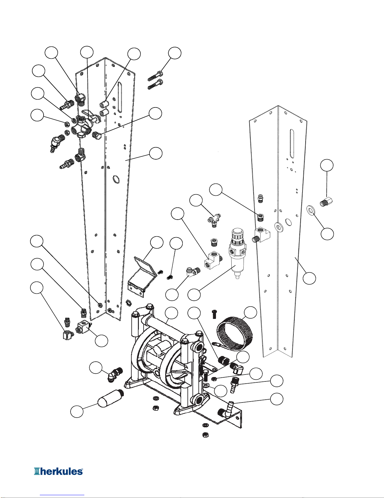
G550 Pump and Legs Layout
17
12
6
13
20
4
3
10
9
719
16
18
2
21
23
22
17
12
6
13
20
4
3
10
9
719
16
28
25
24
27
5
11
6
15
18
26
2
21
1
8
23
14
22
30
32
31
33
Page 11 of 12

Part
#
Description
166 Reducer 3/8 NPT X 1/4 NPT Brass 1 EA
267 Adaptor 1/4 NPT Brass 1 EA
384 Hex Nut 1/4-20 Zinc 4 EA
485 Lock Washer 1/4 Zinc 4 EA
5338 Pump 1 EA
6990 Hose Barb 1/4 X 1/4 NPT Brass 3 EA
712765 Foot pedal 1 EA
813042 Rear Leg 1 EA
913043 Front Leg 1 EA
10 1000818 Tee 5/32 X 1/8 NPT 1 EA
11 1002650 Hose Barb 90° 3/8 X 3/8 NPT Brass 1 EA
12 1002779 Elbow 1/4 NPT Brass 3 EA
13 1002909 Spacer 1/2 OD X .257 ID X 5/8 Nylon 2 EA
14 002-118 Hose Fitting 90° 1/4Tx1/4 NPT 1 EA
15 002-120A-72 Ground Wire 1 EA
16 002-160 Hex Nut 10-32 Zinc 2 EA
17 003-700 Hex Bolt 1/4-20 X 1-1/2 Zinc 2 EA
18 005-134 Reducer 1/4 NPTx1/8 NPT Brass 2 EA
19 005-155 Screw BHSC 10-32 X 3/8 2 EA
20 59B Hex Plug 1/4 NPT Brass 1 EA
21 85D Flat Washer 1/2 SAE Zinc 2 EA
22 C12CX Tee Street 1/4 NPT Brass 2 EA
23 C26 3-Way Valve 1/4 NPT Brass 1 EA
24 M4 Limit Valve 1 EA
25 M6 Elbow 1/8 NPT Brass 1 EA
26 T17M Filter / Regulator 1 EA
27
T25
Hose Fitting 90
°
5/32Tx1/4 NPT
2
EA
Quantity
G550 Pump and Legs Layout
Page 12 of 12
27
T25
Hose
Fitting
90
5/32Tx1/4
NPT
2
EA
28 T4 Hose Fitting 5/32 X 1/8 NPT 3 EA
29 005-131 Screw 10-24 x 1/2 - Stainless 1 EA
30 005-132 Nut Hex 10-24 - Stainless 1 EA
31 83 Bolt Hex 1/4-20 x 1 - Zinc 2 EA
32 001-705 Washer Flat 1/4 USS - Zinc 2 EA
33 1000204 Plastic Muffler 1 EA
Note: Parts are shown for reference purposes only
and are not necessarily part of a Herkules assembly.
Page 12 of 12
Other manuals for G550
1
Table of contents
Other HERKULES Washer manuals

HERKULES
HERKULES G205 User manual

HERKULES
HERKULES GW/R-T User manual

HERKULES
HERKULES G415 User manual

HERKULES
HERKULES G205 User manual

HERKULES
HERKULES G375 User manual

HERKULES
HERKULES G200 User manual

HERKULES
HERKULES G210 User manual

HERKULES
HERKULES G200 User manual

HERKULES
HERKULES G511 User manual

HERKULES
HERKULES G507 User manual


