HERKULES GW/R-T User manual

Part# GW/R-T-OM
1/12/04 TN
Models:
GW/R-T GW/R-2-T GW/R-3-T
Herkules Equipment Corporation 2760 Ridgeway Court Walled Lake, MI 48390-1662 USA
248-960-7100 800-444-4351 Fax 248 960-7109
Patents USA 4793369, 4960142, 5174317, 5193561, 5485860 Canada 1299468 Made in the USA
This manual contains important information concerning the
installation and operation of the gun washers listed above.
Read manual thoroughly and keep for future reference
INSTRUCTIONS
Page 1 of 19
…
Table of Contents
Warnings …………………………………………………………………………………………………………………. 3-4
Model Information (List of models with descriptions and data) ……………………………………………… 5
Installation ……………………………………………………………………………………………………………….. 5
Operation ………………………………………………………………………………………………………………… 6-8
Preventive Maintenance ……………………………………………………………………………………………… 8
Troubleshooting …………………………………………………………………………………………………………. 9
Notes …………………………………………………………………………………………………………………….. 10-11
Timed Diaphragm Pump Assembly Instructions ………………………………………………………………. 12
Timed Diaphragm Pump Assembly Drawings ……………. …………………………………………………. 13
Drawings with part lists:
GW/R-T ……………………………………………………………………………………………………… 14-15
GW/R-2-T …………………………………………………………………………………………………… 16-17
GW/R-3-T …………………………………………………………………………………………………… 18-19
Warning Symbol Caution Symbol
Serial Number
Model Number
Purchase Date
Distributor
CAUTION
WARNING
This symbol alerts you to the possibility of
serious injury or death if you do not follow
the instructions.
This symbol alerts you to the possibility of
damage to or destruction of equipment if you
do not follow the instructions.
Page 2 of 19

EQUIPMENT MISUSE HAZARD
Equipment misuse can cause the equipment to rupture, malfunction, or start unexpectedly
and result in serious injury.
•This equipment is for professional use only.
•Read all instruction manuals, tags, and labels before operating the equipment.
•Use the equipment only for its intended use.
•Do not alter or modify this equipment.
•Do not exceed the maximum working pressure of the lowest rated system component.
•Do not operate the gun washer at a pressure above the maximum working pressure rating of the
gun(s) being cleaned.
•Route the hoses away from traffic areas, sharp edges, moving parts, and hot surfaces.
•Do not use the hoses to pull the equipment.
•Do not move pressurized equipment.
•Use fluids or solvents that are compatible with the equipment wetted parts. Read the fluid and
solvent manufactures warnings
•Comply with all applicable local, state and national fire, electrical and other safety regulation.
PRESSURIZED EQUIPMENT HAZARD
Spray from hose leaks, ruptured components, or from operating the gun washer with an open lid
can splash fluid in the eyes or on the skin and cause serious injury.
•A safety device has been installed to shut off the pump when the gun washer lid is opened.
Do not tamper with or alter this device.
•Open the gun washer lid slowly.
•Do not prop the gun washer lid open with an object or by any other means.
•Do not stop or deflect fluid leaks with your hand, body, glove, or rag.
•Tighten all fluid connections before operating the equipment.
•Replace worn, damaged, or loose parts immediately.
WARNING
Page 3 of 19
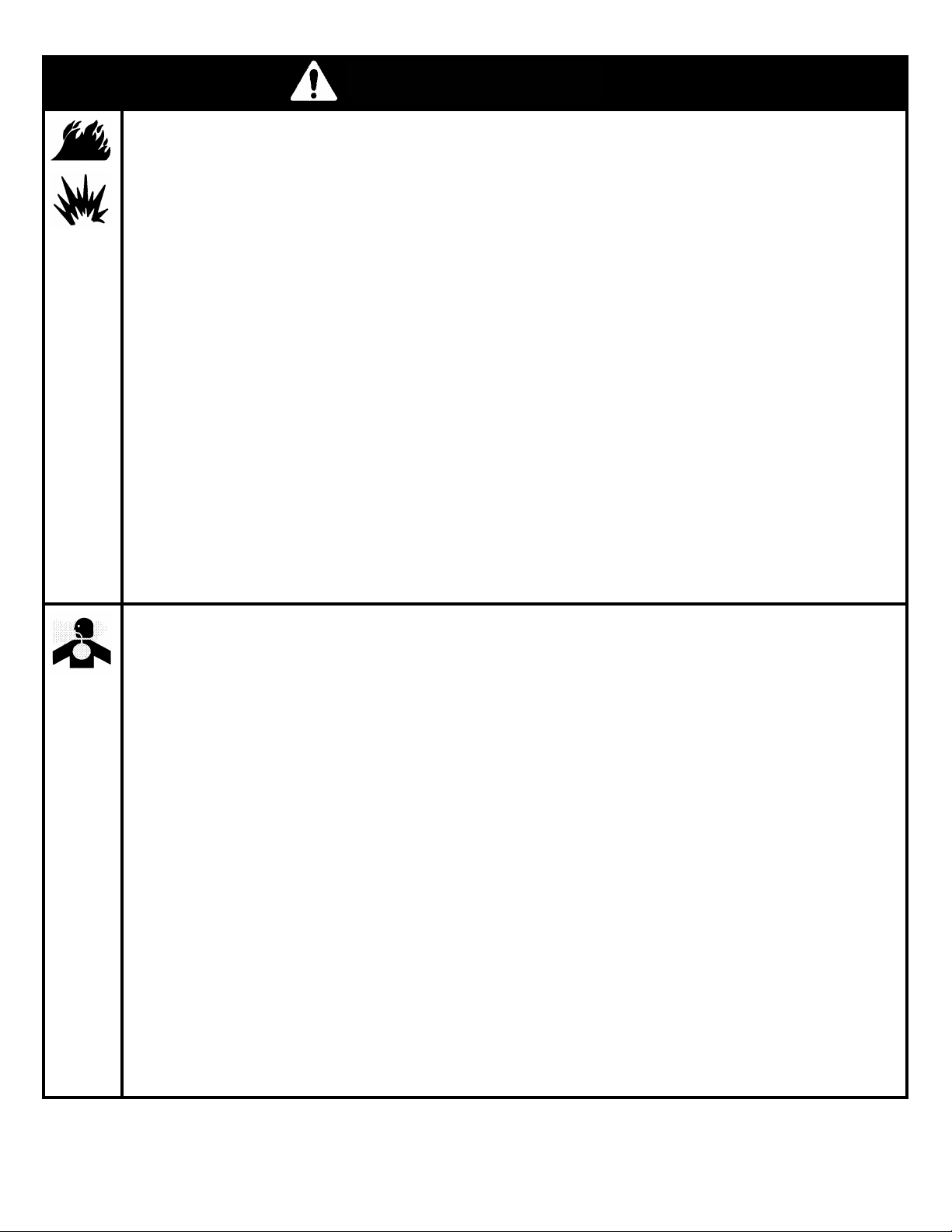
FIRE AND EXPLOSION HAZARD
Improper grounding, poor air ventilation, open flames, or sparks can cause a hazardous condition
and result in fire or explosion and serious injury.
•Ground the equipment. See Installation for grounding procedure.
•Provide fresh air ventilation to avoid the build up of flammable fumes from the solvent.
•Extinguish all open flames or pilot lights in gun washer area.
•Electrically disconnect all equipment in the gun washer area.
•Keep the gun washer area free of debris, including solvent, rags, and gasoline.
•Do not turn on any light switch in the gun washer area while operating or if fumes are present.
•Do not smoke in the gun washer area.
•Do not operate a gasoline engine in the gun washer area.
•Follow the gun manufactures solvent and other cleaning recommendations.
•Use solvent with the highest possible flash point.
•If there is any static sparking while using the equipment, stop operation immediately. Identify and
correct the problem.
•Drain the solvent into a proper storage container when gun washer(s) is not in use.
TOXIC FLUID HAZARD
Hazardous fluids or toxic fumes can cause serious injury or death if splashed in eyes or on the
skin, swallowed, or inhaled.
•Know the specific hazards of the fluid you are using. Read the fluid manufactures warnings.
•Store hazardous fluid in an approved container. Dispose of hazardous fluid according to all local, state
and national guidelines.
•Wear the appropriate protective clothing, gloves, eyewear and respirator.
•Pipe and dispose of the exhaust air safely. If diaphragm fails, the fluid may be exhausted along with
the air.
WARNING
Page 4 of 19

Model Information
NOTE: Dimensions listed are overall measurements. Model shown: GW/R-T
Model Description Weight Dimensions in. (mm)
(kg.)
A
BCD
GW/R-T Two gun, two cup paint gun washer/recycler equipped 74 41.625 20.5 24.375 30.75
with diaphragm pump, filter-regulator and timer. (33.6) (1057) (521) (619) (781)
GW/R-2-T GW/R-T for use with water based cleaning solutions or 74 41.625 20.5 24.375 30.75
standard lacquer thinner solvents. (33.6) (1057) (521) (619) (781)
GW/R-3-T GW/R-T adapted for pressure feed systems, paint 75 41.625 20.5 24.375 30.75
hoses, and cans up to 5 gallons. (34) (1057) (521) (619) (781)
Installation
Installing the Gun Washer 2 Ground all equipment used or located in the
gun washer area.
1 Connect diaphragm pump housing to Gun
Washer. (See page 12) Connecting the Air Line
2 Place gun washer on a level surface in a properly 1 Install a 1/4 in. npt male coupler, that is
ventilated paint mixing room or paint booth. compatible with the quick disconnect of your
air supply line, into the open port of the
Grounding the Gun Washer filter/regulator located at the back of the pump
housing.
1 Connect the ground wire on the gun washer’s
pump to a true earth ground. 2 Connect air line with 90-120 psi to the coupler.
Filter/regulator is preset. Do not adjust.
A
BC
01981000(100)
D
Page 5 of 19

Operation
Filling the Gun Washer with Fluid Placing Equipment in the Gun Washer
1 Close ball valve located on the bottom of the tank. To clean guns not mentioned here, use the long or short
stem supports as needed (see Fig. 2). For questions or
2 Pour five gallons (18.9 liters) of high quality slow adapter kits contact your paint gun washer distributor.
evaporating solvent into the tank. DuPont 3661S or
equivalent is recommended. Siphon Feed Guns
Place the gun siphon tube on the short stem support.
Preparing the Equipment to be washed Gravity Feed Guns
1 Remove paint cup or paint line and the air line from Place long stem support over one of the short stem
the paint gun. supports. Place paint inlet of gun on long stem support.
2 Drain excess paint from cup and gun. *For Gravity Feed, High Volume Low Pressure Guns an
adapter kit (part number 23K) is available for best
3 Remove all gauges and regulators. cleaning.
4 Lock the gun trigger in the open position by placing Pressure Feed Guns
the trigger lock around the gun handle and trigger Place long stem support over one of the shorter stem
(see Fig. 2). supports. Place paint inlet of gun on long stem support.
CAUTION Pots and Cups
All pressure gauges must be removed before placing the Place pots and/or cups on divider platform over front
equipment in the gun washer to avoid damaging the spray nozzles.
gauges.
Figure 2
Trigger Lock
Long Stem Support
Short Stem Support
HVLP Gun Adapter
(Sold Separately)
01001245(206)
Siphon Feed Gun
Paint Cup
Page 6 of 19
Operation
Additional Washing Features of Model
GW/R-3-T
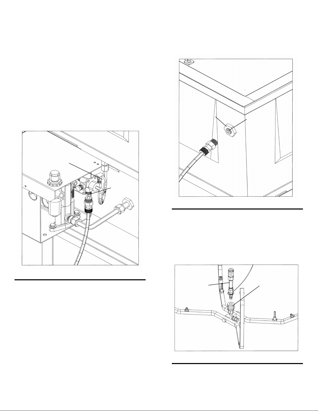
Internal Washing of Paint Lines
Remove the brass plugs from the bottom of the 3-way valve
and the internal wash bulkhead (see Fig. 3 & 4). Install
a female fluid quick coupler with 1/4 in. npt male threads
(suitable for lacquer thinner) into the bottom of the 3-way
valve. Install a female fluid quick coupler with 3/8 in. npt
male threads (suitable for lacquer thinner) into the internal
wash bulkhead. Connect the paint line to the couplers.
Face the pointer of the 3-way valve down and operate the
gun washer.
Figure 4 01981002(105)
Washing Five Gallon Cans
Insert the spray nozzle assembly, hanging on the back
of the manifold, into the Q.D. coupler in the center of
the manifold (See figure 5). Place five gallon can over
spray nozzle.
Operate gun washer.
Figure 3 01981004(104)
Internal Washing of Paint Lines with Guns Attached
Remove the brass hex plug from the bottom of the 3-way valve.
Install a female fluid quick coupler with 1/4 in. npt male
threads (suitable for lacquer thinner). Connect paint line
with gun attached, to the coupler. Face the pointer of the
3-way valve down and operate the gun washer. To “bleed”
the paint (into a container) hold the trigger of the gun open
until clean thinner begins to flow.
Washing Pressure Pot and Lid
Insert the spray nozzle assembly, hanging on the back of the
manifold, into the Q.D. coupler in the center of the manifold Figure 5 01981002(98)
(See figure 6). Place pot over spray nozzle. Place pickup tube
of lid over one of the short stem supports (remove gauges).
Operate gun washer.
Socket plug
#61A
Internal wash
bulkhead
3-way valve
pointer
Hex plug
Spray nozzle
assembly
Q.D. Coupler
Page 7 of 19
Operation
Operating the Gun Washer
1 Make sure all wire trigger locks and other accessories are inside the gun washer tank.
2 If washing only one set of equipment, place empty cans over the unused nozzles and/or stem supports to prevent
solvent spray from hitting the underside of the gun washer lid.
3 Close the gun washer lid.
4 Turn the timer knob clockwise 90 degrees to start the gun washer. The gun washer will run for 90 seconds. Turning
the timer knob less than 90 degrees will reduce the timing cycle. Paint equipment will clean in 60 to 90 seconds.
5 If the lid is opened prior to the end of the timing cycle, the safety air cutoff switch will stop the gun washer. The gun
washer will start again when the lid is closed if time remains on the timer.
Note: Open the lid slowly to minimize solvent vapor escape.
6 Remove the equipment from the gun washer and wipe off any remaining solvent. The gun hanger on the front of the
stand can be used to dry the guns.
Preventive Maintenance
1 Drain excess paint from cup or pot before placing in gun washer.
2 Drain paint sludge from gun washer tank weekly. Do this after a weekend so that it has settled. Open ball valve and
drain until clear solvent flows. Add solvent to 1” above intake filter.
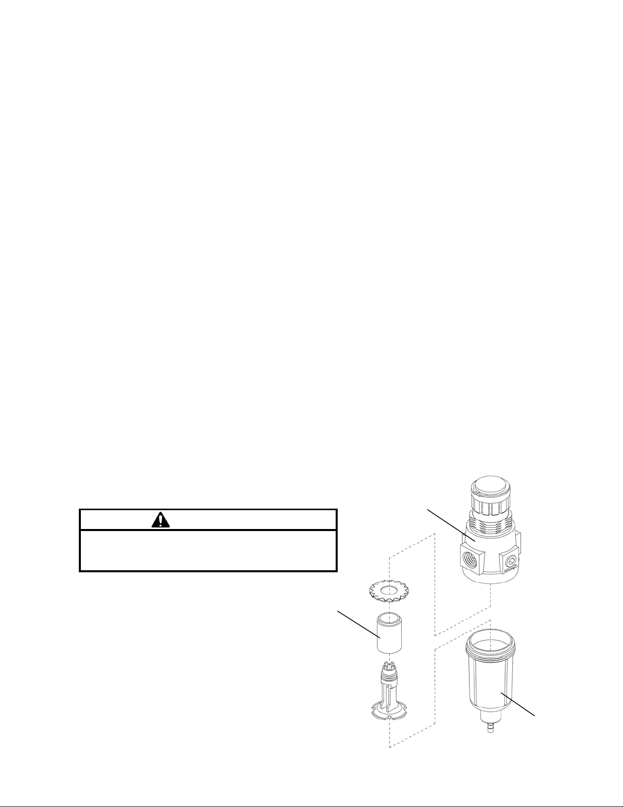
3 Remove the filter bowl and check the filter inside the regulator for excess buildup approx. every 6 months.
4 Change solvent completely when objects being cleaned become tacky to the touch.
5 Clean inside of tub and intake filter before filling with solvent.
CAUTION
Do not change the setting of the filter/regulator.This could
damage the filter/regulator or pump
Filter/Regulato
r
#T17M
Filte
r
#1001382
Filter Bowl
Page 8 of 19

Troubleshooting
Problem Possible Solution
Gun washer will not turn on. 1Make sure the air line is properly connected with 90-120 psi.
2Make sure lid is fully closed. Make sure the limit valve (#M1C) on
the valve bracket (#M1SA) is closed in the downward position.
3 Check all air connections to ensure that there are no leaks.
4 Make sure timer cam is engaging the limit valve (#M1C) on the
pump housing assembly.
5 Make sure timer is on and functioning correctly.
Gun washer turns on but 1 Make sure intake filter (#70) is not clogged (Clean or replace).
pumps slowly or not at all. 2 Make sure the air line is properly connected with 90-120 psi.
3 Check all air connections to ensure that there are no leaks.
4 Drain filter/regulator of water. See number 3 of PREVENTIVE
MAINTENANCE.
5 Make sure there is 5 gallons of clean solvent in the gun washer.
The solvent should be an inch above the intake filter (#70).
6 Make sure lid is fully closed. Make sure the limit valve (#M1C) on
the valve bracket (M1SA) is closed in the downward position.
7 Make sure manifold nozzles and stem supports are not clogged.
Gun washer will not shut off 1 Make sure timer cam (#M230-001A) is moving. If its not, slightly
loosen the nuts holding the limit valve (#M1C) on the top panel of the
pump housing assembly. Reposition valve and tighten nuts.
2Make sure limit valve (#M1C) located on the lid valve bracket assembly
or the pump housing is not stuck in closed position.
Page 9 of 19

Notes
Page 10 of 19

Notes
Page 11 of 19

Diaphragm pump housing assembly instructions
1 Place the two nylon spacers over the housing bolts 3 Tighten the diaphragm pump housing to the
and insert into the gun washer frame holes. Place upper stand.
flat washer, then lock washer, then nut onto the 1”
bolt and finger tighten. 4 Connect air tubing between pump housing
and lid valve bracket.
Note: The timer knob is at the front of the housing
and the air tubing lines are at the rear. a. Connect the blue plastic air tubing running
from the air cut off switch on the pump housing
2 Connect the two metal solvent tubes between the to the in port of the air cut off switch on the lid
pump and the tub. valve bracket. See drawings pages 12-13. The
hose must bottom out in the switch. Pull firmly
Note: Some adjustment of the pump fittings may be to test for tight connection.
necessary. b. Connect the black plastic air tubing running
a. Connect the 3/8” diameter tube between the from the pump housing to the out port of the
“Material Outlet” of the pump and the top outlet of air cut off switch on the lid valve bracket. See
the tub. Finger tighten. drawings pages 12-13. Again the hose must
bottom out in the switch. Pull firmly to test for
b. Connect the 1/2” diameter tube between the tight connection
“Material Inlet” of the pump and the lower outlet of
the tub. Some alignment may be necessary for
proper fitting of all four flare connections. Finger
tighten.
c. When the housing and the solvent tubes are
aligned, tighten the four flare nuts.
Note: When tightening the 1/2” solvent tube, use
a 13/16” open end wrench to hold the flare
fitting in the pump while tightening the 7/8”
flare nut on the solvent tube. This will prevent
pump damage when tightening. Air cut off switch
OUT PORT
01981000(13)
IN PORT
Lid Valve Bracket Assembly
#M1SA
Page 12 of 19
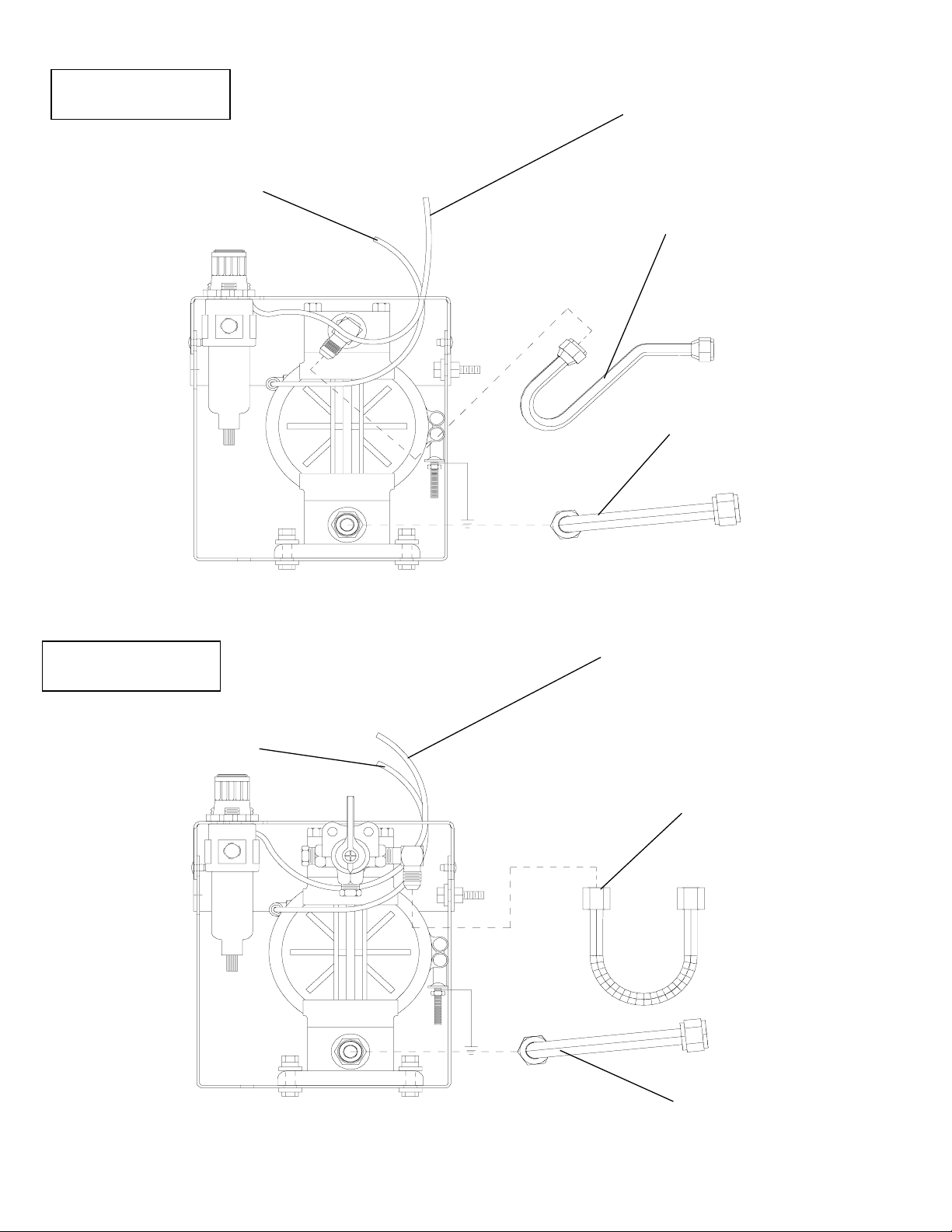
Diaphragm Pump Kit
#10305
Diaphragm Pump Kit
#338DT
1/2” Material Inlet Tube
connect to lower outlet of tub
3/8” Material Outlet Tube
connect to upper outlet of tub
Blue Air Tubing
connect to lid air cut off switch
in port
Black Air Tubing
connect to lid air cut
off switch out port
3/8” Material Outlet Tube
connect to upper outlet of tub
1/2” Material Inlet Tube
connect to lower outlet of tub
Black Air Tubing
connect to lid air cut
off switch out port
Blue Air Tubing
connect to lid air cut off switch
in port
Page 13 of 19
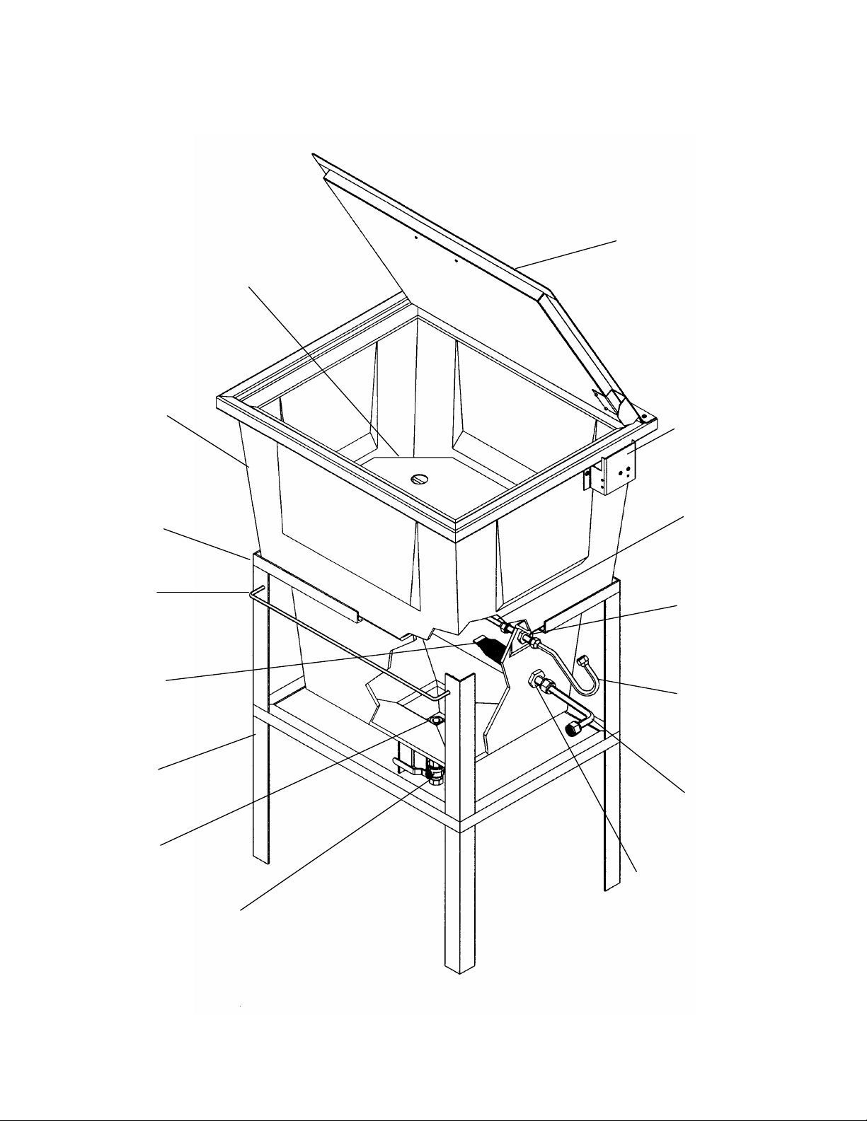
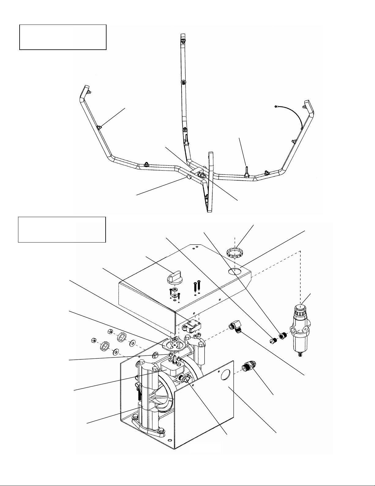
Parts layout for GW/R-T
Divide
r
#25D
Manifold tube
#64A
Tank
#1-BLUE
Ball valve
#6
Inlet tube
#314-003
Outlet tube
#338-006
Intake filter
#70
Gun hange
r
#10045
Lid valve bracket
#M1SA
Lid assembly
#002-096SA
Lower stand
#93DA
Upper stand
#93BA
Bulkhead
#43
Bulkhead
#42
Bulkhead
#41
01981001(75)
Page 14 of 19
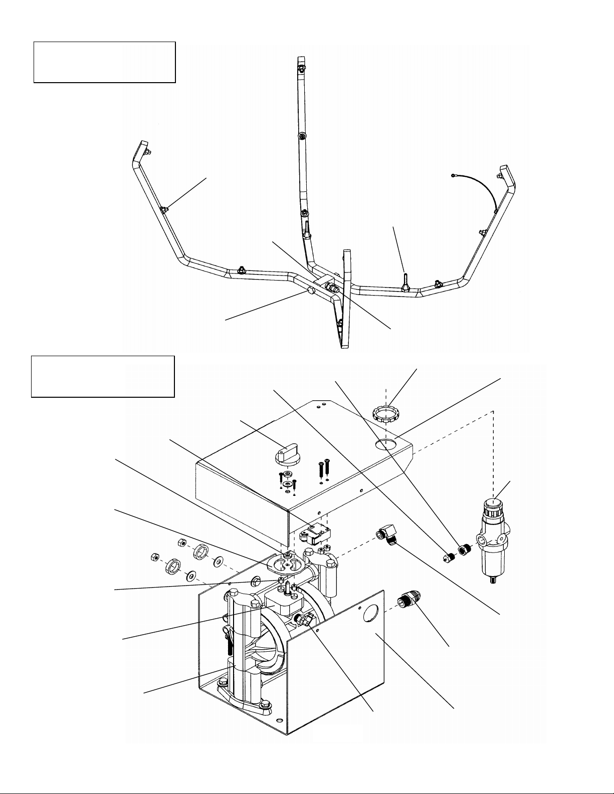
Nozzle
#54P1
Flare fitting
#77
Stem support
#53A
Manifold block
#002-137
Manifold bolt
#002-136
Manifold Assembly
#55A Note:
Parts called out are not necessarily
contained in the assemblies. All parts
are not necessarily shown or called out.
01960510(254)
Timer cam
#M230-003
Pump/Timer Assembly
# 338DT
Filter/Regulator
#T17M
Timer knob
#M230-002
Limit valve
#M1C
Flare fitting
#005-105
Tube fitting
#T25
Lower panel
#11211
Hose barb
#T24
Time
r
#M230-001A
Note:
The following tubing is not shown.
5/32” plastic tubingPart# M5
Regulator nut
#1000215
Reduce
r
#005-134
Flare fitting
#77A
Nylon space
r
#M230-005
Nylon space
r
#M230-004
01981003(200)
Upper panel
#11212
Diaphragm pump 3/8”
#338
Page 15 of 19
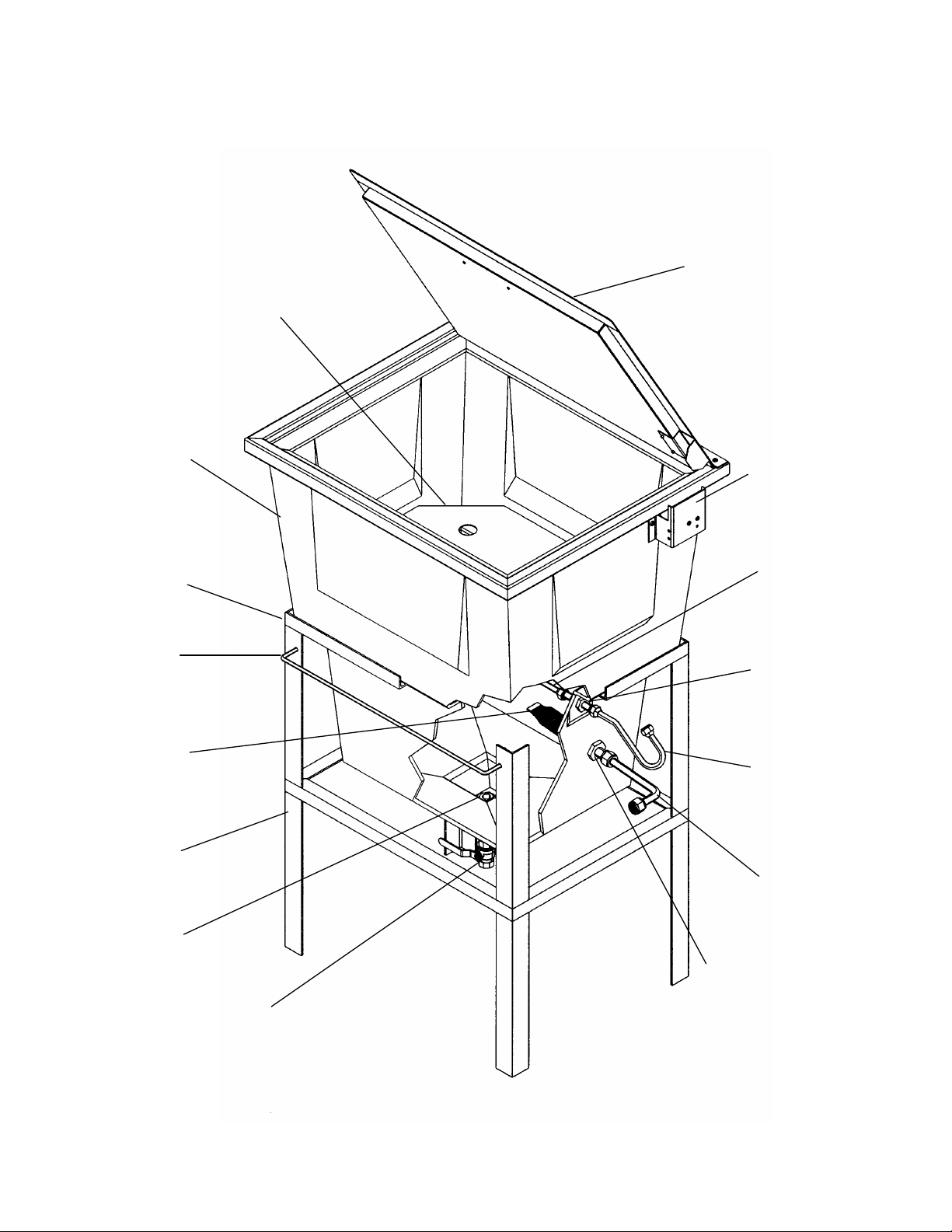
Parts layout for GW/R-2-T
Divide
r
#25D
Manifold tube
#64A
Tank
#1-BLUE
Ball valve
#6
Inlet tube
#314-003
Outlet tube
#338-006
Intake filter
#70
Gun hange
r
#10045
Lid valve bracket
#M1SA
Lid assembly
#002-096SA
Lower stand
#93DA
Upper stand
#93BA
Bulkhead
#43
Bulkhead
#42
Bulkhead
#41
01981001(75)
Page 16 of 19
Nozzle
#54P1
Flare fitting
#1000134
Stem support
#53A
Manifold block
#002-137
Manifold bolt
#002-136S
Manifold Assembly
#55A2 Note:
Parts called out are not necessarily
contained in the assemblies. All parts
are not necessarily shown or called out.
01960510(254)
Timer cam
#M230-003
Filter/Regulator
#T17M
Timer knob
#M230-002
Limit valve
#M1C
Flare fitting
#005-105
Tube fitting
#T25
Lower panel
#11211
Hose barb
#T24
Time
r
#M230-001A
Note:
The following tubing is not shown.
5/32” plastic tubingPart# M5
Regulator nut
#1000215
Reduce
r
#005-134
Flare fitting
#77A
Nylon space
r
#M230-005
Nylon space
r
#M230-004
01981003(200)
Upper panel
#11212
Diaphragm pump 3/8”
#338
Pump/Timer Assembly
# 338DT
Page 17 of 19

Parts layout for GW/R-3-T
Divide
r
#25D
Manifold tube
#64A
Tank
#1-BLUE
Ball valve
#6
Inlet tube
#314-003
Flexible tube
#1000523
Intake filter
#70
Gun hange
r
#10045
01981002(157)
Lid valve bracket
#M1SA
Lid assembly
#002-096SA
Lower stand
#93DA
Upper stand
#93BA
Bulkhead
#11A
Bulkhead
#42
Bulkhead
#41
Bulkhead
#1000135
Plug
#61A
Elbow
#005-105
Page 18 of 19

Nozzle
#54P1
Flare fitting
#77
Stem support
#53A
Manifold block
#002-137D
Manifold bolt
#002-136
Note:
Parts called out are not necessarily
contained in the assemblies. All
parts are not necessarily shown or
called out.
01960414(254)
Adapto
r
#1001107
Hex plug
#59
Manifold Assembly
#10170
Diaphragm pump 3/8”
#338
Timer knob
#M230-002
Timer cam
#M230-003
Limit valve
#M1C
3 way valve
#C26
Tube fitting
#T25
Lower panel
#11211
Hose barb
#T24
Pump/Timer Assembly
# 10305
Time
r
#M230-001A
Note:
The following tubing is not shown.
5/32” plastic tubingPart# M5
Regulator nut
#1000215
Elbo
w
#005-105
Flare fitting
#77A
Nylon space
r
#M230-005
Nylon space
r
#M230-004
01981003(202)
Upper panel
#11212
Reduce
r
#005-134
Filter/Regulator
#T17M
Page 19 of 19
This manual suits for next models
2
Table of contents
Other HERKULES Washer manuals

HERKULES
HERKULES G375 User manual

HERKULES
HERKULES G100 User manual

HERKULES
HERKULES G200 User manual

HERKULES
HERKULES G507 User manual

HERKULES
HERKULES G415 User manual

HERKULES
HERKULES G210 User manual

HERKULES
HERKULES G200 User manual

HERKULES
HERKULES G550 User manual

HERKULES
HERKULES G205 User manual

HERKULES
HERKULES G511 User manual


