HERKULES G205 User manual

Part# 1002531
12/12/2005
Herkules Equipment Corporation 2760 Ridgeway Court Walled Lake, MI 48390-1662 USA
248-960-7100 800-444-4351 Fax 248 960-7109
Patents USA 4793369, 4960142, 5174317, 5193561, 5485860 Canada 1299468 Made in the USA
This manual contains important information concerning the
installation and operation of the gun washers listed above.
Read manual thoroughly and keep for future reference
INSTRUCTIONS
Page 1 of 20
Table of Contents
Warnings ……………………………………………………………………………………………………………………… 3-4
Assembly Instructions ……………………………………………………………………………………………………….. 5-7
Model Information ……………………………………………………………………………………………………………. 8
Installation ………………………………………………………………………………………………………………….. 8
Operation ……………………………………………………………………………………………………………………. 9-10
Preventive Maintenance ………………………………………………………………………………………………………. 10
Troubleshooting ……………………………………………………………………………………………………………… 11
Drawings with part lists: …………………………………………………………………………………………………… 12-20
Warning Symbol Caution Symbol
Serial Number
Model Number
Purchase Date
Distributor
CAUTION
WARNING
This symbol alerts you to the possibility of serious
injury or death if you do not follow the instructions. This symbol alerts you to the possibility of damage to
or destruction of equipment if you do not follow the
instructions.
Page 2 of 20
EQUIPMENT MISUSE HAZARD
Equipment misuse can cause the equipment to rupture, malfunction, or start unexpectedly
and result in serious injury.
•This equipment is for professional use only.
•Read all instruction manuals, tags, and labels before operating the equipment.
•Use the equipment only for its intended use.
•Do not alter or modify this equipment.
•Do not exceed the maximum working pressure of the lowest rated system component.
•Do not operate the gun washer at a pressure above the maximum working pressure rating of the
gun(s) being cleaned.
•Route the hoses away from traffic areas, sharp edges, moving parts, and hot surfaces.
•Do not use the hoses to pull the equipment.
•Do not move pressurized equipment.
•Use fluids or solvents that are compatible with the equipment wetted parts. Read the fluid and
solvent manufacturer's warnings
•Comply with all applicable local, state and national fire, electrical and other safety regulation.
PRESSURIZED EQUIPMENT HAZARD
Spray from hose leaks, ruptured components, or from operating the gun washer with an open lid
can splash fluid in the eyes or on the skin and cause serious injury.
•A safety device has been installed to shut off the pump when the gun washer lid is opened.
Do not tamper with or alter this device.
•Open the gun washer lid slowly.
•Do not prop the gun washer lid open with an object or by any other means.
•Do not stop or deflect fluid leaks with your hand, body, glove, or rag.
•Tighten all fluid connections before operating the equipment.
•Replace worn, damaged, or loose parts immediately.
WARNING
Page 3 of 20
FIRE AND EXPLOSION HAZARD
Improper grounding, poor air ventilation, open flames, or sparks can cause a hazardous condition
and result in fire or explosion and serious injury.
•Ground the equipment. See Installation for grounding procedure.
•Provide fresh air ventilation to avoid the build up of flammable fumes from the solvent.
•Extinguish all open flames or pilot lights in the gun washer area.
•Keep the gun washer area free of debris, including solvent, rags, and gasoline.
•Do not turn on any light switch in the gun washer area while operating or if fumes are present.
•Do not smoke in the gun washer area.
•Do not operate a gasoline engine in the gun washer area.
•Follow the gun manufacturer's solvent and other cleaning recommendations.
•Use solvent with the highest possible flash point.
•If there is any static sparking while using the equipment, stop operation immediately. Identify and
•correct the problem.
Drain the solvent into a proper storage container when gun washer(s) is not in use.
TOXIC FLUID HAZARD
Hazardous fluids or toxic fumes can cause serious injury or death if splashed in eyes or on the
skin, swallowed, or inhaled.
•Know the specific hazards of the fluid you are using. Read the fluid manufacturer's warnings.
•Store hazardous fluid in an approved container. Dispose of hazardous fluid according to all local, state
and national guidelines.
•Wear the appropriate protective clothing, gloves, eyewear and respirator.
•Pipe and dispose of the exhaust air safely. If diaphragm fails, the fluid may be exhausted along with
the air.
WARNING
Page 4 of 20

Assembly
Stand and tub connections
STEP 1
Attach the four legs to the frame using (4) 1/4-20 x 1/2"
hex bolts, (4) #10 flat washers, (4) 1/4" lock washers
and (4) 1/4" acorn nuts per leg (see fig.1). Hand tighten
(2) 1/4-20 x 5/8" hex bolts where noted in fig.1.
Note: The leg assembly containing the timer and the
leg assembly containing the filter/regulator must be
positioned as shown in fig.1 .
STEP 2
Position the pump mount bracket between the timer
leg assembly and the filter/regulator leg assembly.
Attach the pump mount bracket to the stand using (2)
1/4-20 x 3/4 hex bolts, (2) #10 flat washers, (2)
1/4" lock washers and (2) 1/4" acorn nuts per leg
(see fig.1).
STEP 3
Attach the pump to the stand using the (2) 1/4-20 x 1
hex bolts, (2) 1/4" flat washers, (2) 1/4" lock washers
and (2) 1/4" hex nuts per leg (see fig.2).
STEP 4
Attach the ball valve to the lower bulkhead on the
bottom of the tub (see fig.3).
STEP 5
Attach the white plastic muffler to the exhaust
port of the pump (see fig.3).
STEP 6
Slide (1) #10 flat washer then (1) 1/8" nylon spacer
then the timer knob over the shaft protruding from
the timer leg assembly (see fig.3)
fig.3
Ball valve
Muffler
Hex bolt
1/4-20 x 1
1/4" Hex nut
1/4" Lock washer
Flat washer 1/4
fig.2
fig.1
Hex bolt
1/4-20 x 1/2
Flat washer #10
1/4" Acorn nut
1/4" Lock
washer
Hex bolt
1/4-20 x 1/2
Flat washer #10
1/4" Acorn nut
1/4" Lock
washer
Timer Leg
Filter/Regulator
Leg
Hex bolt
1/4-20 x 5/8
Page 5 of 20

Assembly
Connecting fluid and air hoses
STEP 7
Connect the black 5/32" air hose between the regulator
and the air in port of the limit valve located on the rear leg
of the gun washer. Press tubing in through the collar until
seated. Pull firmly on hose to test for a tight connection.
(see fig.4).
Note: Air in port of limit valve is the port opposite the roller.
STEP 8
Connect the blue 5/32" air hose between the air in port of
limit valve located on the front leg and the air out port of the
limit valve located on the rear leg of the gun washer.
Press tubing in through the collar until seated. Pull firmly on
hose to test for a tight connection (see fig.4).
STEP 9
Connect the clear 5/32" air hose between the pump and
the air out port of the limit valve located on the front leg
of the gun washer. Press tubing in through the collar until
seated. Pull firmly on hose to test for a tight connection, then
place the tub in the stand, bulkheads near the pump (see fig.4).
STEP 10
Connect the solvent tubes from the solvent transfer panel
to the gun washer as shown in fig. 6.
STEP 11
Attach the panel to the stand using (2) 10-24 x 3/4 screws
(2) 10-24 lock nuts, (2) 1/4" lock washers and (2) 1/4" acorn
nuts (see fig.5).
Note: 1/4" acorn nuts and 1/4" lock washers were installed
in step 1.
STEP 12
Insert the hose hanger into 1/4" slot in the panel (see fig. 5).
Limit valve
Limit
valve
Clear air
hose
Upper bulkhead
Lower
bulkhead
fig.4
Black air
hose
Blue air
hose
Connect to upper
pump fitting
Connect to lower
pump fitting
Connect to upper tub
bulkhead
Connect to lower tub
bulkhead
Solvent fill hose
Connect to recycler
outlet (or new
solvent container) Solvent drain hose
Connect to recycler
inlet (or old solvent
container)
fig.5
1/4" Acorn nut
1/4" Lock
Washer
10-24 X 3/4
Screw
Hose hanger
fig.6
Page 6 of 20

Assembly
Connecting lid rod and actuator linkage
STEP 12
Slide the actuator over the lid rod opposite the drilled end and
hand tighten approx. 4" from the end of the rod. Insert the
actuator into the large slot in the right rear leg (see fig 8).
STEP 13
Attach the lid rod to the lid bracket using the 1/4" clevis pin
and circular cotter pin supplied (see fig. 7).
STEP 14
To adjust the actuator, close the lid and loosen the set
screw on the actuator. Slide the actuator down until it
completely closes the limit valve and retighten the set
screw (see fig. 8).
Grounding the lid
STEP 15
Using an 1/8" allen wrench, remove the back right lid screw.
Connect the ground wire (with the aluminum terminal
attached) from the pump to the lid screw and reconnect it
to the tub (see fig. 7).
fig.7
Lid screw
Ground wire
Lid rod
Cotter pin
Lid bracket
Clevis pin
fig.8
Lid rod
Actuator
Set screw
Page 7 of 20

Model Information
Parts bag contents
001-600A S-hook 1 ea.
001-705 Flat washer 1/4 2 ea.
001-702 Hex bolt 1/4-20 x 1/2 16 ea.
002-161 Flat washer #10 19 ea.
002-175 Bolt BHSC 10-24 x 3/4 2 ea.
005-137 Nut hex 10-24 - nylock 2 ea.
008-244 Acorn nut 1/4-20 18 ea.
6 Ball valve 1 ea.
83 Hex bolt 1/4-20 x 1 2 ea.
84 Hex nut 1/4-20 2 ea.
85 Lock Washer 1/4 20 ea.
1000652 Clevis pin 1/4 dia. 1 ea.
1000252 Cotter pin 1 ea.
1000116 Hex bolt 1/4-20 x 5/8 2 ea.
11957 Actuator 1 ea.
C9A Nipple 1/8 NPT X 4-1/2 2 ea.
53B Stem support female 2 ea.
M5 Tube 5/32 blue plastic 30 in.
M5-BLACK Tube 5/32 black plastic 9 in.
M5-NEUTRAL Tube 5/32 clear plastic 13 in.
NOTE: Dimensions listed are overall measurements.
Model Description Weight Dimensions in. (mm)
(kg.)
A
BCD
G205 Two gun, two cup paint gun washer equipped with 68 46 20.625 24.5 21.25
a solvent transfer system (31) (1168) (524) (622) (540)
Installation
Installing the Gun Washer
1) Place gun washer on a level surface in a properly
ventilated paint mixing room or paint booth.
Grounding the Gun Washer
1) Connect the ground wire on the gun washer’s pump to a
true earth ground.
2) Ground all equipment used or located in the gun washer
area.
Connecting the Air Line
1) Install a 1/4 in. npt male coupler, that is compatible with
the quick disconnect of your air supply line, into the air
supply port of the filter/regulator located on the right rear
leg (see fig. 9).
2) Connect air line with at least 75 psi to the coupler.
Filter/regulator is preset. Do not adjust.
Air supply
port
fig.9
A
BC
D
Page 8 of 20

Operation
Filling the Gun Washer with Fluid Placing Equipment in the Gun Washer
1) Close ball valve located on the bottom of the tank. To clean guns not mentioned here, use the long or short
stem supports as needed (see Fig. 10). For questions or
2) Connect the solvent fill hose to the clean solvent container. adapter kits contact your paint gun washer distributor.
Note: If using a solvent recycling system, connect the solvent Siphon Feed Guns
fill hose to the recycler outlet. Place the gun siphon tube on the short stem support.
3) Position both valves on the side panel to fill. Turn the timer Gravity Feed Guns (HVLP)
to the on position. Pump five gallons (18.9 liters) of high Place long stem support over one of the short stem
quality solvent into the tub. This requires approx. 1-1/2 timer supports. Place paint inlet of gun on long stem support.
cycles. Place the air cap assembly over the air inlet of the gun to
keep solvent out.
Preparing the Equipment to be washed Pressure Feed Guns
1) Remove paint cup or paint line and the air line from the Place long stem support over one of the shorter stem
paint gun. supports. Place paint inlet of gun on long stem support.
2) Drain excess paint from cup and gun. Pots and Cups
3) Remove all gauges and regulators. Place pots and/or cups on divider platform over front
spray nozzles.
4) Lock the gun trigger in the open position by placing the
trigger lock around the gun handle and trigger (see fig. 10).
CAUTION
All pressure gauges must be removed before placing the
equipment in the gun washer to avoid damaging the
gauges.
Trigger Lock
Long Stem Support
Short Stem Support
Gravity Feed
Gun (HVLP)
Siphon Feed Gun
Paint Cup
Pressure Feed Gun
A
ir Cap
A
ssembly
fig. 10
Page 9 of 20
Operation
Operating the Gun Washer 7) Remove the equipment from the gun washer and wipe off
any remaining solvent.
1) Make sure all wire trigger locks and other accessories
are inside the gun washer tub. Draining the Gun Washer
2) If washing only one set of equipment, place empty cans over 1) Place a 5-gallon bucket underneath the gun washer
the unused nozzles and/or stem supports to prevent
solvent spray from hitting the underside of the gun washer lid. 2) Place the filtered intake hose into the bucket.
3) Close the gun washer lid. 3) Open the ball valve located on the bottom of the tank and
drain the used solvent into the bucket.
4) Position both valves on the side panel to clean.
4) Connect the solvent drain hose to the used solvent
5) Turn the timer knob clockwise 90 degrees to start the gun container.
washer. The gun washer will run for 90 seconds. Turning
the timer knob less than 90 degrees will reduce the timing Note: If using a solvent recycling system, connect the
cycle. Paint equipment will clean in 60 to 90 seconds. solvent drain hose to the recycler inlet.
6) If the lid is opened prior to the end of the timing cycle, the Position both valves on the side panel to drain. Turn the
safety air cutoff switch will stop the gun washer. The timer to the on position.
gun washer will start again when the lid is closed if time
remains on the timer.
Note: Open the lid slowly to minimize solvent vapor escape.
Preventive Maintenance
1) Drain excess paint from cup or pot before placing in gun
washer.
2) Drain paint sludge from gun washer tank weekly. Do this
after a weekend so that it has settled. Open ball valve
and drain until clear solvent flows. Add solvent to 1” above
intake filter.
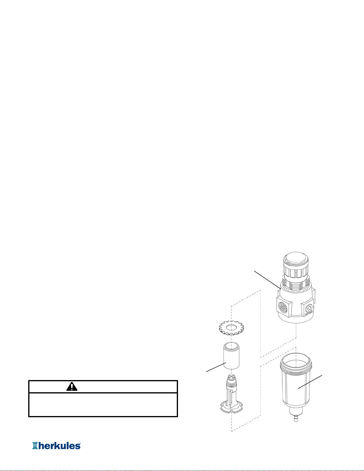
3) Remove the filter bowl and check the filter inside the
regulator for excess buildup approx. every 6 months.
4) Change solvent completely when objects being cleaned
become tacky to the touch.
5) Clean inside of tub and intake filter before filling with solvent.
CAUTION
Do not change the setting of the filter/regulator.This could
damage the filter/regulator or pump
Filter/Regulato
r
#T17M
Filte
r
#1001382 Filter Bowl
Page 10 of 20

Troubleshooting
Problem Possible Solution
Gun washer will not turn on. 1Make sure the air line is properly connected with at least 75 psi.
Air pressure is regulated at 75 psi.
2Make sure lid is fully closed. Make sure the lid rod actuator is making
full contact with the limit valve on the right rear leg.
3 Check all air connections to ensure that there are no leaks.
4 Make sure timer cam is engaging the limit valve on the right front leg.
5 Make sure timer is on and functioning correctly.
Gun washer turns on but 1 Make sure intake filter is not clogged (Clean or replace).
pumps slowly or not at all. 2 Make sure the air line is properly connected with at least 75 psi.
Air pressure is regulated at 75 psi.
3 Check all air connections to ensure that there are no leaks.
4 Make sure there is 5 gallons of clean solvent in the gun washer.
The solvent should be an inch above the intake filter.
5Make sure lid is fully closed. Make sure the lid rod actuator is making
full contact with the limit valve on the right rear leg.
6 Make sure manifold nozzles and stem supports are not clogged.
Gun washer will not shut off 1 Make sure timer cam is moving. If its not, slightly loosen the nuts
holding the limit valve on the right front leg of the stand. Reposition
valve and tighten nuts.
2Make sure limit valves located on the right front leg or right rear leg
of the stand are not stuck in closed position.
Page 11 of 20
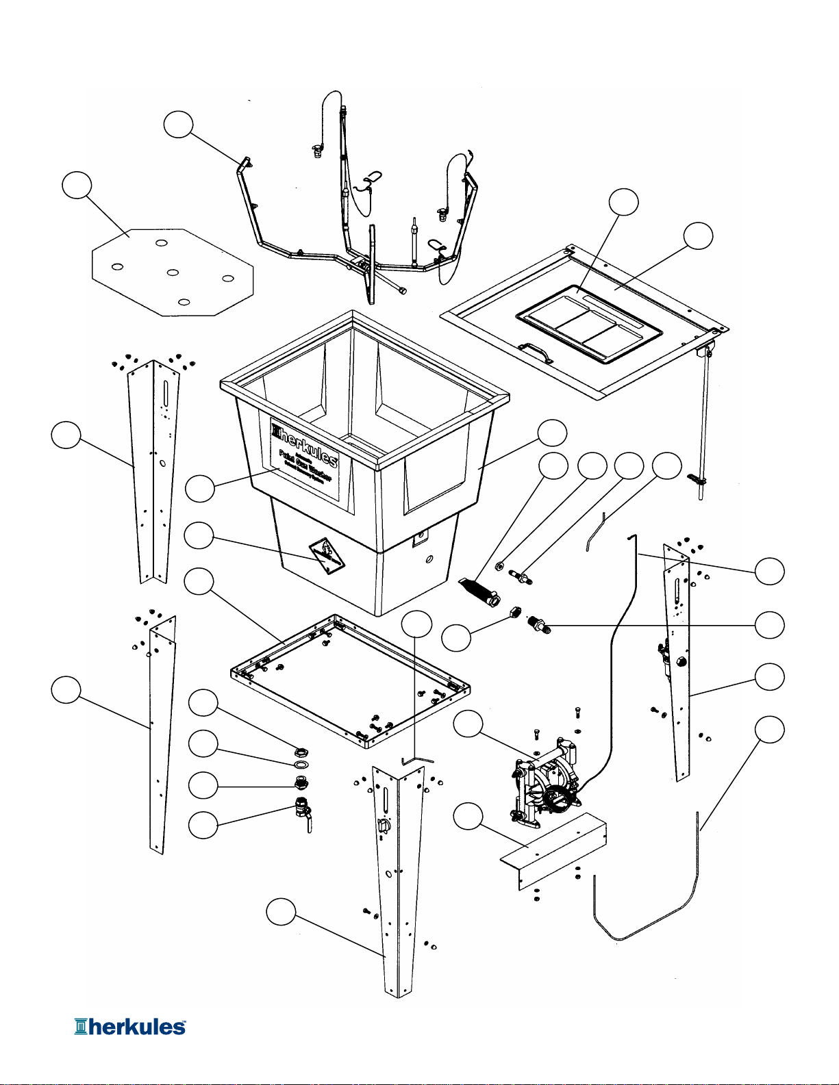
G205 Parts Layout
1
2
3
4
5
6
7
8
9
10
11
12
13
14
15
16
17
18
19 20 22 25
21 23
24
26
27
Page 12 of 20

G205 Parts Layout
Part # Description Quantity
155A Manifold Assembly 1 EA. See pg. 15
225D Divider - Stainless 1 EA.
31001706 Front Decal 1 EA.
41000651 Flammable Caution Sticker 1 EA.
511418 Stand Frame 1 EA.
644 Nut Hex 1-14 UNS - Brass 2 EA.
785B Washer 1-1/2 x 1 - Nylon 1 EA.
841 Bulkhead 1-14 UNS x 1/2 NPT - Brass 1 EA.
96 Ball Valve 1 EA.
10 1002378 Leg 1 EA.
11 1002378 Leg 1 EA.
12 12211 Timer Leg Assembly 1 EA. See pg. 16
13 12210 Filter Leg Assembly 1 EA. See pg. 16
14 11958 Pump Mounting Bracket 1 EA.
15 11962 Pump Assembly 1 EA. See pg. 16
16 1-BLUE Tub 1 EA.
17 11961 Lid Assembly 1 EA. See pg. 16
18 1001708 Lid Sticker 1 EA.
19 70 Filter for Pump Inlet 1 EA.
20 45 Nut Hex 9/16 - 18 UNF - Brass 1 EA.
21 44 Nut Hex 1-14 UNS - Brass 2 EA.
22 43 Bulkhead 3/8 T x 3/8 T - Brass 1 EA.
23 42 Bulkhead 1-14 UNS x 1/2 T - Brass 1 EA.
24 M5 Tube 5/32 Plastic - Blue 30 IN.
25 M5-BLACK Tube 5/32 Plastic - Black 9 IN.
26 M5-NEUTRAL Tube 5/32 Plastic - Neutral 13 IN.
27 002-120A-72 Ground Wire 2 EA.
Note: For parts shown but not identified
refer to assembly layouts on pages 13-17.
Page 13 of 20

G205 Lid Layout
Part # Description Quantity
11002546 Screw 10-24 x 1/2 4 EA.
21000252 Actuator Clip Ring 1 EA.
31000652 Actuator Pin 1 EA.
41001708 Lid Sticker 1 EA.
510A Handle 1 EA.
611219 Lid 1 EA.
711232 Lid Stop 1 EA.
811957 Actuator Bracket Notched 1 EA.
911963 Actuator rod 1 EA.
10 12025 Lid Bracket 1 EA.
11 14C Rivet 3/16 x 1/2 - Aluminum 4 EA.
12 17 Rivet 3/16 x 1/4 - Stainless 2 EA.
13 39C Hinge 2 EA.
Note: Parts are shown for reference purposes only
and are not necessarily part of a Herkules assembly.
3271
5
8
9
11 13 12
1064
Page 14 of 20
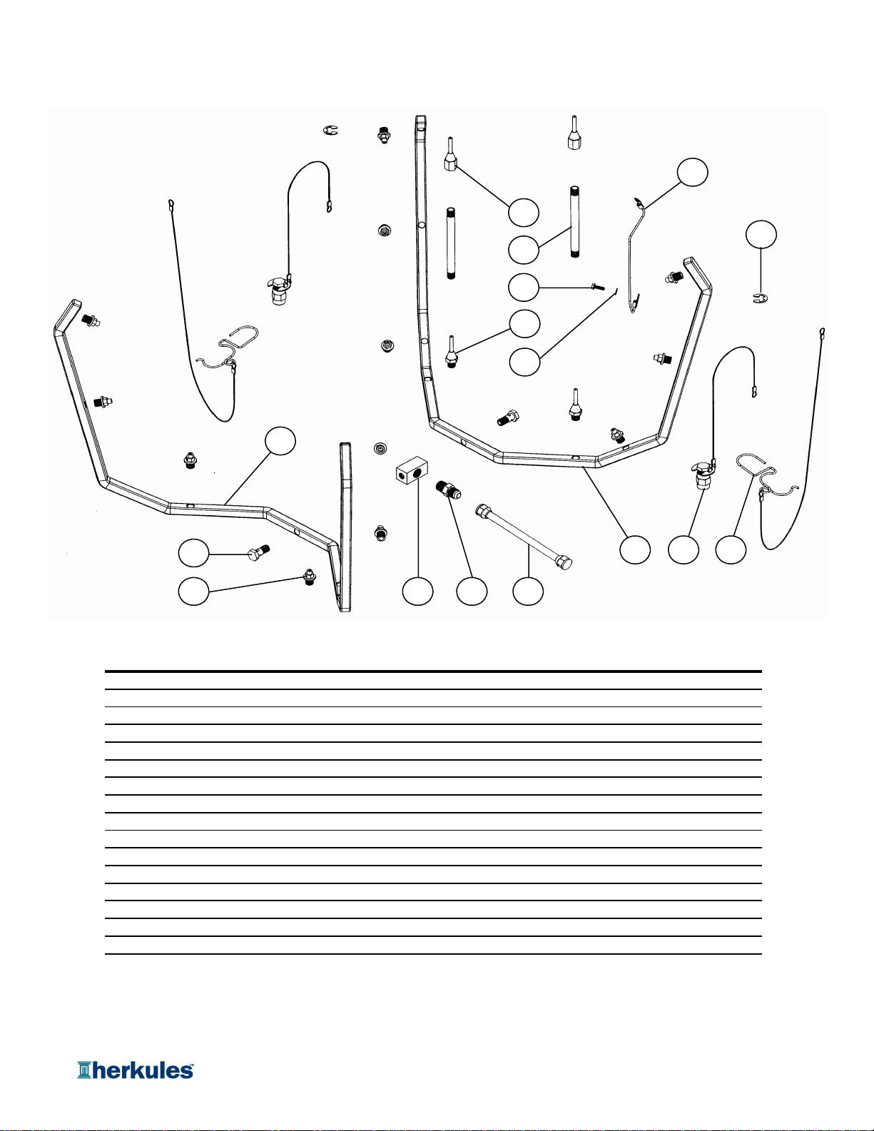
G205 Manifold Layout
Part # Description Quantity
1002-109 E-ring 2 EA.
2002-113B Internal Tube with Nuts - Stainless 1 EA.
3002-121A-6 Manifold Ground Wire 1 EA.
4002-136S Manifold Bolt 2 EA.
5002-137 Manifold Block 1 EA.
6005-119 Manifold Ground Wire Screw 1 EA.
710612 Air Cap Assembly 2 EA
81000134 Fitting 3/8 T x 1/4 NPT - Nickel 1 EA.
922BA Trigger Lock Assembly 2 EA.
10 24E Ground Wire Lock Washer 1 EA.
11 53A Stem Support Male 2 EA.
12 53B Stem Support Female 2 EA
13 54P1 Full jet Nozzle - White 12 EA.
14 55SB Manifold Half B - Stainless 1 EA.
15 55SR Manifold Half A - Stainless 1 EA.
16 C9A Nipple 4-1/2" - Brass 2 EA.
Note: Parts are shown for reference purposes only
and are not necessarily part of a Herkules assembly.
12
14
13 8 2
11
7 9
5
3
6
16
10
15
1
4
Page 15 of 20
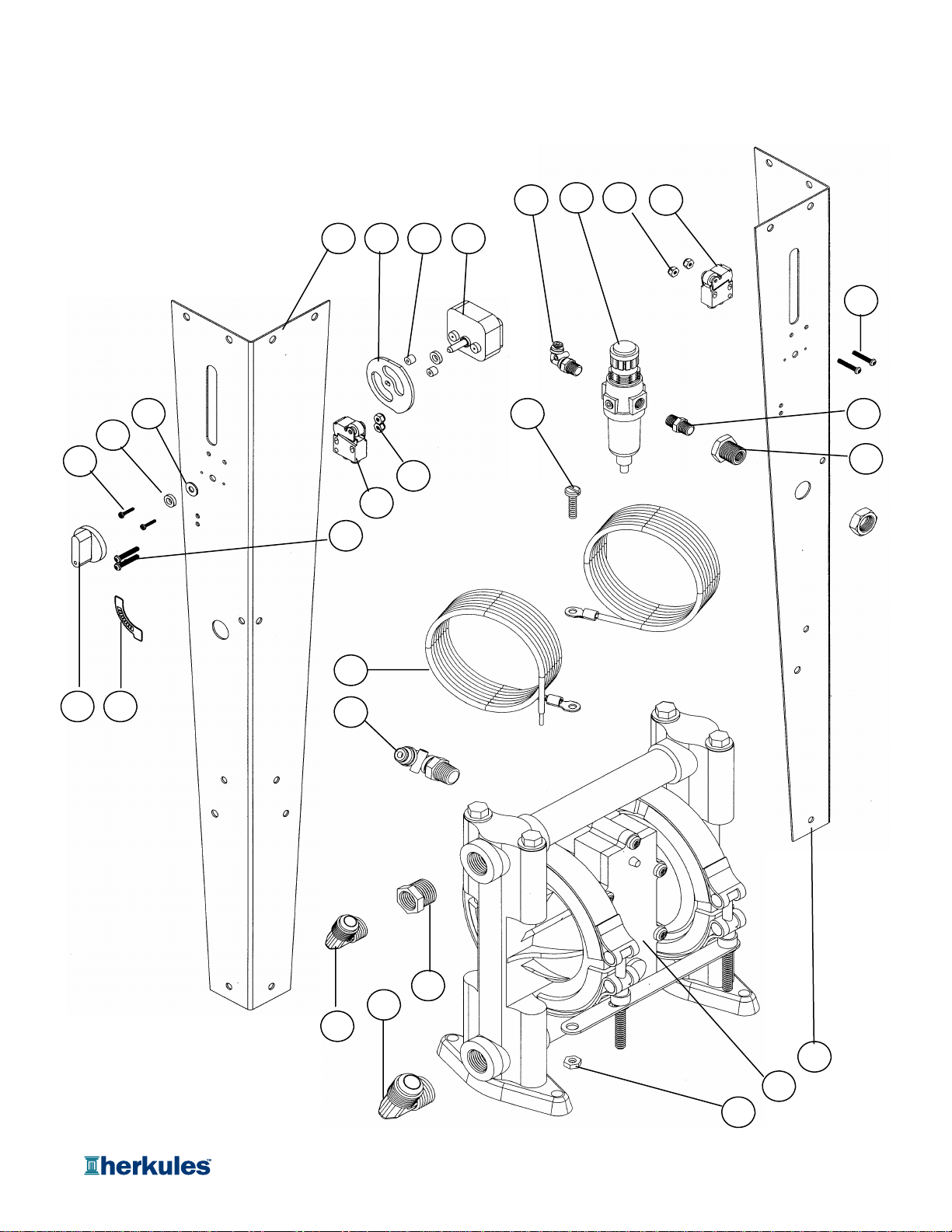
G205 Pump and Legs Layout
2
24
27
5
28 25 6
3
23 10 79
11
1
12
21
4
26
22
8
17
18
13
20
19
15
14
16
Page 16 of 20

G205 Pump and Legs Layout
Part # Description Quantity
1002-161 Washer Flat #10 USS - Zinc 1 EA.
2002-171 Screw 8-32 x 1 - Black 2 EA.
3002-172 Nut Nylock 8-32 - Zinc 2 EA.
41002414 ON/OFF Sticker 1 EA.
51002378 Leg 1 EA.
6M1C Limit Valve - Gold 1 EA.
7M230-001A Timer 1 EA.
8M230-002 Knob for Timer 1 EA.
9M230-003 Cam For Timer 1 EA.
10 M230-004 Spacer 1/4" Thick - Nylon 2 EA.
11 M230-005 Spacer 1/8" Thick - Nylon 1 EA.
12 M230-006 Timer Screw #4 x 5/8 2 EA.
13 002-120A-72 Ground Wire 2 EA.
14 005-105 Elbow 3/8 T x 1/4 NPT - Zinc 1 EA.
15 005-106 Elbow 1/2 T x 3/8 NPT - Brass 1 EA.
16 005-131 Screw 10-24 x 1/2 - Stainless 1 EA.
17 005-132 Nut Hex 10-24 - Stainless 1 EA.
18 338 Pump 1 EA.
19 66 Reducing Bsh. 3/8 NPT x 1/4 NPT 1 EA.
20 T25 5/32 Hose fitting 90° Swivel 1 EA.
21 002-171 Screw 8-32 x 1 - Black 2 EA.
22 002-172 Nut Nylock 8-32 - Zinc 2 EA.
23 1002378 Leg 1 EA.
24 11A Filter Bulkhead with Nut 1 EA.
25 T17M Filter / Regulator 1 EA.
26 M1C Limit Valve - Gold 1 EA.
27 M25 Hex Nipple 1/4 NPT - Brass 1 EA.
28 T25 5/32 Hose Fitting 90° Swivel 1 EA.
Note: Parts are shown for reference purposes only
and are not necessarily part of a Herkules assembly.
Page 17 of 20
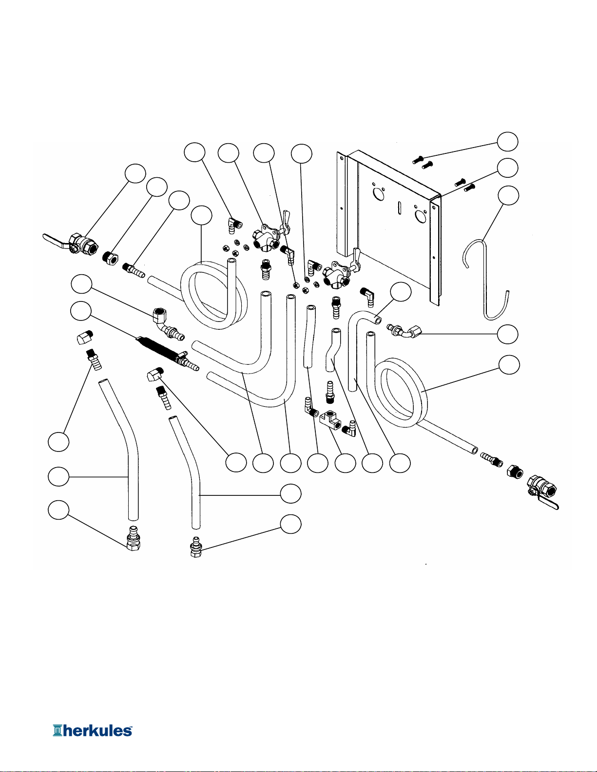
G205 Panel Layout
15
9
16
24 23
17
10
20
11
21
27
26
3
25
1
19
7
22
12
18
5
13
8
14
13
62 4
Page 18 of 20

G205 Panel Layout
Part # Description Quantity
1C26 Valve 4-Way 1/4 npt Brass 2 EA.
2C12BX Tee 1/4 npt Brass 1 EA.
366B Reducer 1/2 npt x 1/4 npt Brass 2 EA.
4100-084 Hose 3/8 ID Blue 3.63 IN.
5100-084 Hose 3/8 ID Blue 5.63 IN.
6100-084 Hose 3/8 ID Blue 9 IN.
7100-084 Hose 3/8 ID Blue 29 IN.
8100-084 Hose 3/8 ID Blue 96 IN.
9100-084 Hose 3/8 ID Blue 96 IN.
10 100-084 Hose 3/8 ID Blue 12 IN.
11 100-083 Hose 1/2 ID Blue 18 IN.
12 100-083 Hose 1/2 ID Blue 18 IN.
13 002-131 Elbow 1/4 npt Brass 2 EA.
14 1002467 Hose Barb 1/2 X 1/4 npt Brass 2 EA
15 1002466 Panel 1 EA
16 1000981 Hose Barb 3/8 npt x # 6 Flare 1 EA.
17 1000967 Hose Barb 90 Deg 3/8 X 1/4 npt Brass 6 EA.
18 1000869 Hose Barb 1/2 npt x # 8 Flare 1 EA.
19 1000841 Hose Barb 90 Deg 3/8 x # 6 Flare 1 EA.
20 1000840 Hose Barb 90 Deg 1/2 x # 8 Flare 1 EA.
21 1000767 Bolt BHSC 1/4-20 X 3/4 Black 4 EA.
22 11243 Filter Assembly 1 EA
23 85 Washer Lock 1/4 Zinc 4 EA.
24 84 Nut Hex 1/4 Zinc 4 EA.
25 57 Hose Barb 3/8 X 1/4 npt Brass 5 EA
26 6 Ball Valve 1/2 npt Brass 2 EA
27 001-600A S-Hook 1 EA
Note: Parts are shown for reference purposes only
and are not necessarily part of a Herkules assembly.
Page 19 of 20

G205 Hardware Layout
Part # Description Quantity
1001-702 Bolt Hex 1/4-20 x 1/2 - Zinc 16 EA.
2001-705 Washer Flat 1/4 USS - Zinc 2 EA.
3002-161 Washer Flat #10 USS - Zinc 18 EA.
4008-244 Acorn Nut 1/4-20 - Nickel 18 EA.
583 Bolt Hex 1/4-20 x 1 - Zinc 2 EA.
684 Nut Hex 1/4-20 - Zinc 2 EA.
785 Washer Lock 1/4 - Zinc 20 EA.
81000116 Bolt Hex 1/4-20 x 5/8 - Zinc 2 EA.
5
2
4
3
4
76
7
4
31
8
Page 20 of 20
Other manuals for G205
1
Table of contents
Other HERKULES Washer manuals

HERKULES
HERKULES G200 User manual

HERKULES
HERKULES G507 User manual

HERKULES
HERKULES G200 User manual

HERKULES
HERKULES G415 User manual

HERKULES
HERKULES GW/R-T User manual

HERKULES
HERKULES G210 User manual

HERKULES
HERKULES G550 User manual

HERKULES
HERKULES G375 User manual

HERKULES
HERKULES G205 User manual

HERKULES
HERKULES G511 User manual


