Herr little extra User manual

We used and recommend the Hitec™HS-55 Feather Servos for
this model. Of course you can use different brands of servos but
make sure they are the same size, weight, and output as the
HS-55 units.
IMPORTANT SERVO NOTE: The Hitec™HS-55 servos we used
in this kit all had off-the-shelf servo lead lengths of 10-1/2". This
meant that we did not have to add servo extensions to these
servos to reach the center of the wing. If you are using servos with
shorter leads, you will likely have to add servo lead extensions.
For receivers, we have used the Hitec™#555, the Hitec™Electron
6 and the FMA M5 units. All three of these receivers are dual
conversion types. These receivers are light, have excellent range
and, because they are dual conversion types, they are perfect for
use at any typical R/C flying field. We do not recommend using
single conversion receivers for this model.
We used a Hitec™270 mAh NiCad airborne battery pack for our
Little Extra models. In actual use, we found that after being fully
charged, we could fly for an honest 40 minutes or so before
needing to be recharged. The Y-harness is used to join the two
aileron servos and the 6" servo extension is required to connect
the ailerons to the receiver. We used the small Hitec™On/Off
switch assembly in the interest of weight and size.
Finally, the transmitter you use for this model is important. For our
Little Extra ARF models, we used both the Hitec™Flash 4 and the
Airtronics®RD-6000 transmitters. Both of these affordable
systems offer multi-model memory and a host of easy-to-use
computer features that make radio set-up and flying a whole
easier and much more fun. If you do not use these transmitters or
similar units, the set-up and flying of your model is going to be
more difficult.
ENGINE SELECTION:
As previously mentioned, the Little Extra ARF was specifically
designed to fly very nicely using the Norvel™.074 BigMig R/C
engine. The use of this recommended engine provides really
1
INTRODUCTION
Congratulations on the purchase of the HERR ENGINEERING
Little Extra ARF kit! The Little Extra is one of the first true high
performance 1/2A fun-fly R/C type models to be available in an
Almost Ready to Fly format. Like larger fun-fly type sport models,
the Little Extra is loaded with a lot of features and truly
exhilarating performance potential. The airframe is very light,
beautifully built and engineered to last a long time. The covering
has been professionally applied and the trim scheme is just about
perfect for this type of model. The assembly process is very quick
and further enhanced by the completeness of the kit.
Properly powered and flown, the Little Extra is a very capable
fun-fly type model! The airplane itself has been specifically
designed around the powerful little Norvel .074 BigMig R/C
engine. The kit includes a custom-cut motor mount assembly
specifically for this engine and even includes a custom aluminum
spinner insert for the spinner, designed to fit the .074 prop shaft.
In the air you will find it hard to believe that such a small model can
fly so "big". The Little Extra is fully capable of just about any R/C
maneuver you care to throw at it - point rolls, snaps, knife-edge,
inverted flight, lomcevaks, etc. Who knew flying small gas
powered models could be so fun! Herr Engineering, that’s who.
To take full advantage of the Little Extra’s potential flight envelope,
we urge you to carefully review this Assembly Manual, paying
particular attention to the radio and battery equipment
suggestions. These suggestions are based upon a lot of
experience with this design and should be heeded. The success
of this model is based upon its light ready-to-fly weight, so you
want to be sure your airborne equipment is as light as possible.
Finally, the Little Extra ARF design is not intended as a beginner's
R/C model. The design assumes that you are a proficient R/C
pilot, capable of flying relatively high-performance model aircraft.
RADIO EQUIPMENT
As mentioned previously, it is very important to select the correct
airborne radio equipment for your Little Extra ARF model. This
Assembly Manual will show the use of the following equipment.
This equipment is what we have used and can highly recommend
for the Little Extra ARF:
• 5 Micro Servos (Hitec™HS-55 Servos used, (Hitec™P/N 31055*)
• 1 Micro Receiver (see suggested receivers below)
• 1 270-300 mAh Airborne Battery Pack (Hitec™P/N 57405*)
• 1 Hitec™Miniature Switch Harness (Hitec™P/N 54403*)
• 1 Hitec™6" Y-Harness (Hitec™P/N 57351*)
• 1 Hitec™6" Servo Extension (Hitec™P/N 57344*)
(*With these part numbers you must specify the connector type for your radio system)

good power margins and excellent high speed-low speed
characteristics. Using larger engines is not recommended. Larger
engines weigh more and will cause CG problems.
COVERING MATERIAL:
Your Little Extra ARF has been professionally covered using
SIG AEROKOTE-LITE™iron-on covering film. This is a low
temperature covering film that is both very tough and light,
weighing only 5.9 grams per square foot. For reference, the
AEROKOTE-LITE™colors used on this model are:
#SIGSGX204 Cream and #SIGSGX241 Turquoise or
#SIGSGX100 Brilliant White and #SIGSGX360 Violet
If you live in a drier climate, you may notice that some wrinkles
might develop after removing the covered parts from their plastic
bags. This is does not mean that the covering is defective! Your
model was built and covered in a part of the world with relatively
high humidity and therefore the wood was likely carrying a fair
amount of moisture. When exposed to drier air, wood typically
loses this moisture, dimensionally "shrinking" in the process. In
turn this may cause some wrinkles. However, wrinkles are easy to
remove by just using a hobby type heat iron. Remember that with
thin structures, such as the tail group and ailerons, excess heat
will warp them. Therefore, be careful when applying heat to
remove a wrinkle - a Trim Seal tool, with a small shoe is always
best for these kinds of surfaces - be sure to use the low heat
setting on this tool.
For reshrinking AEROKOTE-LITE™set your iron temperature
to approximately 140O-180OF (60O-82OC).
Use the iron to go completely over all seams and color joints,
making sure they are all well sealed and secure. If a wrinkle is
found, hold the hot iron over the wrinkle to lightly shrink the
material - do not press on it. Once the covering is tight, lightly iron
it back down to the wood. Be careful with the iron when working
around any seams. Overheating a seam may cause the covering
to creep, exposing the wood beneath. Also, use caution when
working with heat around the canopy area - heat will distort this
clear plastic material.
REQUIRED TOOLS:
For proper assembly, we suggest you have the following tools and
materials available:
A selection of glues - SIG Thin and Thick CA
and SIG Kwik-Set 5-Minute Epoxy
Threadlock Compound, Such as Loctite®#242 Non-
Permanent Blue
Screwdriver Assortment
Pliers - Needle Nose and Flat Nose
Diagonal Wire Cutters
Small Allen Wrench Assortment
Small Power Drill With Selection of Bits
Pin Vise for Small Dia. Drill Bits
Hobby Knife With Sharp #11 Blades
Scissors
Heat Iron and Trim Seal Tool
Masking Tape
Paper Towels
COMPLETE KIT PARTS LIST:
The following is a complete list of all parts contained in this kit.
Before beginning assembly, we suggest that you take the time to
inventory the parts in your kit.
AIRCRAFT PARTS:
Bag #1 Vertical Fin and Rudder Assembly (with 3 unglued hinges
in place)
Bag #2 Horizontal Stabilizer and Elevator Assembly (with 6 unglued
hinges in place)
Bag #3 Wing Assembly with Ailerons (with 4 unglued hinges in
place for each aileron)
Bag #4 Fuselage Assembly (with rudder & elevator pushrod tubes
installed and canopy installed)
Bag #5 2 1mm x 126mm
Aileron Pushrods Z-Bend
1 1mm x 325mm
Throttle Pushrod with Z-Bend
1 1mm x 495mm
Rudder & Elevator Pushrods with Z-Bend
1 Sub Bag (a) 1 4-40 x 1" Nylon Wing Bolt
4 Control Horns
5 Pushrod Keepers
Bag #6 2 42mm x 58mm Plastic Aileron Hatch/Mount Covers
4 7.2mm x 10.2mm Hardwood Aileron Servo Mounting
Blocks
1 Plywood Aileron Positioning Guide (APG)
1 6mm x 12mm x 63mm Balsa Fuel Tank Retainer
2
MODELER'S TIP: A method to avoid damaging seams and
joints when reshrinking the covering is to protect them with
paper towels soaked in cold tap water and rolled into strips.
These are then arranged directly onto the joints or seams and
their coolness protects the seam from shifting or "crawling"
under heat.

3
4 M2.6 x 12mm PWA Engine Mounting Screws
1 Sub Bag (a) 8 M2 x 5mm PWA Aileron Hatch
Cover Screws
Bag #7 1 Pre-Bent Aluminum Main Landing Gear
1 Sub Bag (a) 2 2" Dia. Main Wheels
1 Sub Bag (b) 2 M3 x 25mm Wheel Axle Bolts
4 M3 Hex Nuts
2 M3 Lock Nuts
4 M3 Flat Washers
2 9mm PWA Screws
2 M3 x 10mm PWA Bolts
2 M3 Split Ring Lock Washers
1 Sub Bag (c) 1 Tail Wheel Wire
1 Brass Tail Wheel Mounting Bracket
2 M2 x 6mm PWA Screws
1 15mm Dia.Tail Wheel
Bag #8 1 1-1/2" Dia. SIG Spinner Assembly
1 Sub Bag (a) 2 2.6mm x 10mm Assembly Screws
1
4mm Prop Shaft Adaptor
(Norvel
™
.074)
Bag #9 2 Wheel Pants, 1 Left, 1 Right, Factory Painted
Bag #10 1 Fuel Tank Assembly
1 Sub Bag (a) 1 Metal Clunk
3 Metal Fuel Tank Lines
1 Rubber Tank Stopper
With Mounting Hardware
Little Extra Decal Sheet
Little Extra Assembly Manual
ASSEMBLY:
To avoid unnecessary "dings", dents, or scratches, we suggest
covering your workbench with a sheet of light foam or an old
blanket to protect the pre-covered parts. We also suggest that you
fully charge the transmitter and airborne battery pack for use in the
following assembly steps.
WINGS:
The wing in your Little Extra ARF kit is fully assembled and ready
to use. Note that the aileron hinges are in place, but are NOTyet
glued in place.
❑1)
The ailerons are now hinged to the trailing edge of the wing.
The supplied hinges are the CA type. Remove the ailerons from
each wing panel, keeping the left aileron with the left wing panel
and the right aileron with the right panel. Remove the eight (8)
hinges. Note that the method used for hinging the ailerons is the
same method that will be used to hinge the rudder and elevators.
The hinges have a die-cut center in them that can be used to
accurately place and center the hinge equally into both the wing
panel and the aileron. To do this, use a business card and a pair
of scissors to cut eight or so "wedges". These should be wide
enough at the top so as to not pass through the cut out in the
center of the hinge. Press the hinges into the pre-cut hinge
slots in the wing panel up to the hinge slot cut out. Place a card
wedge into each hinge center and then press the aileron in place
onto each exposed hinge half, up to the card wedges. Align the
outer tip of the aileron with the wing panel tip. The hinges are now
in proper position for permanently gluing in place with thin CA
glue.
Flex the aileron downward about 30Oor so, exposing both sides
of each hinge between the wing and aileron. Use a piece of
masking tape to hold the aileron in this position. For CA hinges,
we always suggest using a fine-tipped applicator on the glue
bottle to have better control of the flow. Remove the wedge from
one of the hinges and apply four small drops of thin CA glue to
each hinge edge. Remove the wedge from the next hinge and
again apply four drops of glue to each hinge edge. Repeat this
process for the remaining two hinges. Remove the tape holding
the flexed aileron to the wing panel and flex the aileron in the
opposite direction, again taping it to the wing to hold it in position.
Turn the wing over and apply four drops of thin CA glue to each
edge of the exposed hinges. Remove the tape and return the
aileron to its neutral position. It takes about 10 minutes for the CA
glue to fully wick its way across the surface of the hinge. Clean off
any spilled glue with SIG Debonder.
After sufficient time has passed, flex the aileron firmly up and
down on the wing panel to create free and easy movement. We
also suggest pulling on the aileron at each hinge location to be
sure that they are firmly in place. Repeat this procedure to hinge
the opposite aileron in place.
❑2) Each aileron has two pre-drilled control horn mounting
holes at their leading edges, directly behind the aileron servo
openings. From the kit contents, locate the two plastic control
horns. Note that the control horns are to be mounted on the
bottom of each aileron, facing forward to the aileron servo
openings. Use thick CA glue for this step. Apply a small amount
of glue to each of the two "spikes" on the control horn. Apply an
additional dab of glue to the base of the control horn, between the
two "spikes". Press the two control horn spikes into the two

4
pre-drilled holes and against the bottom of the aileron. Repeat this
procedure to attach the opposite aileron control horn. The
exposed "spike" ends on the top of each aileron can be easily
trimmed using a single edge razor blade.
❑3) From the kit contents, locate the following parts:
2 Plastic Aileron Hatch/Mount Covers
4 Hardwood Aileron Servo Mounting Blocks
8 M2 x 5mm PWA Hatch Mounting Screws
(For this step you will also need both of your aileron servos.)
Note that the aileron servo mount hatches are oriented on the
bottom of the wing with their output arm slots on the wingtip side
and closest to the aileron control horns, as shown.
The bottom surfaces of both aileron hatch/mount covers are now
lightly sanded, using 220-grit sandpaper. Move the servo output
arm to position it at 90Oto the servo body. Hold the aileron servo
in place on the sanded side of one of the aileron hatch covers.
Move the servo to center the servo arm within the slot, leaving
equal clearance on both sides, as shown. This is the position that
the servo is mounted.
Hold the servo to the tray in the correct position with a small piece
of tape. Apply some thick CA glue to one end of one of the
hardwood mounting blocks and press it in place next to the servo,
beneath its mounting lug and use CA accelerator to set the glue.
Apply glue to the end of another mounting block and press it in
place on the opposite side of the servo, beneath the mounting lug.
Remove the tape and the remove the servo.
Use a small diameter drill to make pilot holes in the hardwood
mounting blocks, using the servo itself as a hole guide. Mount the
servo to the hardwood blocks using the screws provided with your
servos. Repeat this process with the remaining servo tray to make
a "mirror image" servo mount for the opposite wing panel.
❑4) In this step the aileron servo leads will be routed from the
aileron servo bay, through the wing and out through the two
center holes in the top center of the wing. Carefully note the
pre-installed string in the wing for this purpose. In each servo
opening you will see a small scrap of balsa with string tied to it.
This scrap balsa piece has been lightly glued into the bay and is
easily broken loose.
Once the string is loose, remove the scrap balsa piece. Carefully
tie and tape the aileron servo lead to the end of the string.
From the top center of the wing, begin to pull the string and servo
lead through the wing. Do this gently, using a little back and forth

5
movement if the connector hangs up anywhere within the wing.
Once the lead is out of the center hole, remove the string from the
connector. Leave a little slack in the lead and tape it temporarily
to the top of the wing. Turn the wing over and carefully position
each servo into its opening in the bottom of the wing.
The hatch covers are now mounted in place. From the kit
contents, locate the two Aileron Pushrod Wires - 1mm dia. x
126mm long. Attach one of the pushrods to the outermost hole in
the servo output arm, using the end with the Z-bend. Hold the
hatch in place in the wing and align the opposite end of the
pushrod with one side or the other of the control horn. Slide the
hatch left or right in the wing opening until the pushrod wire is at,
or close to 90Oto the trailing edge. This is the position the hatch
should be mounted to the wing. Use a piece of masking tape to
hold the servo tray to the surface of the wing. Use a pointed dowel
or sharp pencil to carefully mark the position of the four hatch
mounting holes onto the surface of the wing.
Use a pin vise or power tool to drill small diameter pilot holes
through the surface of the wing for the mounting screws (Note:
The wing has plywood plates installed beneath the hatch mount
area to accept and hold the mounting screws). Mount the
hatches to the bottom of the wing using the eight provided
M2 x 5mm PWA screws - do not over-tighten these screws, just
cinch them in place to establish the threads. Now remove all of the
hatch screws and set them aside for now.
❑5) Remove the output arm retaining screws from both aileron
servos and then remove the output arms. Connect both servo
leads to theY-harness and plug theY-harness lead into the aileron
channel in your receiver. Connect your On/Off switch lead into the
receiver and the battery pack to the switch. Turn on your
transmitter and make sure the aileron trim lever is in dead neutral.
Turn on the airborne system with the switch and move the
transmitter aileron stick to confirm that he servos are both moving.
Reinstall both of the servo output arms to the aileron servos,
making sure they are at 90Oto the servo body.
Next, move the transmitter stick to confirm that the servos are
moving in the correct direction to produce right and left movement
to the ailerons. If they are not moving in the correct directions, use
the servo reversing feature on your transmitter to reverse their
movement - this may require that you will again have to reposition
the output arms to 90O. After you confirm that the servos are
moving in the correct direction and that the output arms are in the
correct position, secure the output arms to the servos with their
retaining screws.
The servos/servo hatches are now installed into each wing panel
and their mounting screws secured. Turn off the airborne radio
system and disconnect the switch and the Y-harness from the
receiver and the battery from the switch. Turn off your transmitter.
❑6) The aileron pushrods are now connected to the aileron
servos and the aileron control horns. For this step you will need
the 2 Aileron Pushrods, 2 plastic Pushrod Keepers, and the
plywood Aileron Positioning Guide (APG).
a) In order to correctly size and install the pushrods, the
ailerons themselves must be placed and held in the neutral
position. To do this, have a couple of pieces of masking tape
handy, about 3" long. Hold the APG in place to the wing and
aileron as shown. Use a piece of tape along the hinge line to hold
the aileron in this position.

Remove the tape holding the ailerons in neutral. You can now test
the operation of the ailerons with your radio system. The ailerons
should move smoothly with transmitter stick movements and the
ailerons should be moving in the correct directions (right aileron
movement raises the right aileron and lowers the left aileron).
Recheck the centering of the ailerons using the APG tool. If some
adjustment is needed, use a pair of needle nose pliers to open or
close the "V"-bend in the pushrod. Finally, we suggest you put the
APG tool in your field box in case you need it again in the future.
With the exception of adding the decals, the wing is now complete
and ready to use.
MOUNTING THE TAIL GROUP:
❑1) The elevators are now hinged to the horizontal stabilizer,
using the same hinging method as the ailerons. NOTE: The right
elevator half has two pre-drilled holes, near its inboard leading
edge, to accept the control horn. Make sure when hinging the
elevators to the stabilizer, it is with these holes on the right side.
❑2) The horizontal stabilizer and elevator assembly is now
glued in place to the fuselage. First mount the wing to the
fuselage with the provided 4-40 x 1" nylon wing-mounting bolt.
Trial fit the stabilizer in place into the slot at the rear of the
fuselage. Visually center the stabilizer in top view. Use a tape
measure or ruler to measure the distance from the tip of the
aileron to the tip of the stabilizer and note the measurement. Take
the same measurement on the other side of the model - the two
measurements should be the same or within 1/16" or so of each
other. Also make sure the slot in the center of the stabilizer is
aligned directly beneath the vertical fin slot at the top rear of the
fuselage. Use the vertical fin to check that it fits in place without
leaning one way or the other.
Turn the wing over and use another piece of tape along the hinge
line to temporarily "lock" the aileron in this neutral position.
Repeat this process with the opposite aileron. When viewing the
wing from the side, the two ailerons should now be aligned with
each other and in the neutral position to the wing.
b) Attach the "Z"-bend end of the pushrod to the exposed servo
output arm, making sure the "V"-bend is facing away from the
wings surface. Attach opposite pushrod in the same manner. Slip
a plastic Pushrod Keeper onto each pushrod, with its arm facing
to the control horn, as shown.
c) Hold the pushrod end against the control horn, at its
outermost hole location. Use a fine tipped marker to mark the
pushrod wire at the control horn hole location.
Remove the pushrod from the servo output arm and use a good
pair of pliers to now bend the wire to a 90Oangle at the mark just
made. Trim the bent end of the wire to a length of 3/16" and
lightly sand off any burrs on the cut end. Reinstall the pushrod to
the servo output arm and press the bend end of the pushrod
through the control horn hole. Slide the Pushrod Keeper back to
the control horn and flex its arm over the wire end. Press the
keeper in place over the wire and against the control horn. Repeat
this process on the opposite aileron.
6
X
X = SAME DIMENSION
X

With a hobby knife and a sharp #11 blade, carefully cut a "V" notch
in the leading edge of the rudder, from the hole just drilled, down
to the bottom of the rudder. This notch has to be deep enough to
fully accept the .046 dia.tail wheel wire. Test fit the tail wheel wire
in place into the hole and notch in the rudder. Adjust the notch as
needed to fully "nest" the wire into the rudders leading edge.
Mix a small amount of 5-minute epoxy. Slide the tail wheel
mounting plate out of the way, down to the tail wheel itself. Use a
pin or thin object to apply glue into the drilled hole and into the "V"
notch. Press the tail wheel wire into the rudder. Wipe of any
excess glue with alcohol and allow the glue to set.
❑5) The rudder is now hinged to the vertical fin. Slip the three
rudder hinges into the two hinge slots in the trailing edge of the
vertical fin and the hinge slot at the rear of the fuselage. Center
the hinges and slip the card stock wedges into their center slots.
Press the rudder in place to the exposed ends of the three hinges,
all the up to the fin and fuselage. Make sure the top of the rudder
is aligned with the top of the fin. Use a piece of masking tape to
hold the rudder hard over to elevators. Turn the fuselage over,
remove one of the card wedges and use thin CA glue to apply 3
or 4 drops of glue to each edge of the exposed hinge at the hinge
line. Move to the next hinge and repeat this process to glue the
remaining hinges in place. Remove the tape, and hold the rudder
7
Remove the stabilizer from the fuselage and mix a small amount
of 5-minute epoxy. Apply a thin layer of glue to the top and bottom
of the stabilizer slot - very little is actually needed. Slide the
stabilizer/elevator assembly carefully back in place into the
fuselage. Once again, align the stabilizer squarely to the fuselage
per the above instructions. With everything aligned, set the model
on a flat surface and stand back a few feet to view it directly from
the front. The stabilizer should be parallel with the wing in front
view. If it is tilting one way or the other, use tape or small weights
to pull it back into alignment. Clean any excess glue with a fresh
paper towel and alcohol and allow the glue to set.
❑3) The vertical fin is now glued in place into the slot at the top
rear of the fuselage. Mix a small amount of 5-minute epoxy and
apply a thin layer of glue to the inside of the fuselage slot and to
the exposed wood on both sides of the bottom of the vertical fin.
Press the fin carefully in place all the way. Wipe off any excess
glue with alcohol and a fresh paper towel. Again place the model
on a flat surface and view it head on in front view from a few feet
away. The fin must be at 90Oto the fuselage and horizontal
stabilizer. This can be easily checked with a small 90Osquare, as
shown. Use a piece of tape from the top of the fin to the tip of the
stabilizer to hold the fin in this position and allow the glue to set.
When the epoxy has cured, remove the wing from the fuselage.
❑4) Before hinging the rudder to the vertical fin and fuselage,
the wire tailwheel assembly is installed. From the kit contents,
locate the Tail Wheel Assembly bag. Use a ruler to measure a
point 7/16" from the very bottom of the rudder, at its leading edge
- mark this point with a fine tip marker.
At the mark, use a pointed "punch" to poke a small guide hole in
the center of the rudder hinge line, at 90Oto the leading edge. This
small hole is now drilled to a depth of about 3/8" into the leading
edge of the rudder, again, at 90Oto the leading edge, using a .046"
dia. drill bit and a pin vise.

body and check to see if the bent end of the tubing is close to the
top of the tank. Pull the stopper out and adjust the tubing as
required. Keep checking the fit of the tubing inside the tank until it
is right. We always make it a habit to chamfer the bent end of the
overflow line to eliminate any blockage of air.
❑2) Use the shortest piece of aluminum tubing for the fuel
pick-up line. Insert the tubing through the rubber stopper. Fit the
smaller diameter rear metal clamping plate over the vent and fuel
pick-up tubes at the rear of the stopper. Adjust the two tubes as
needed to bring them close to the rear of this plate, leaving 3/16"
of tubing exposed for the fuel pick-up line.
Slip the larger diameter front clamping plate over the two tube
ends at the front of the rubber stopper. Insert the clamping bolt
through the front clamping plate and through the rubber stopper
back to the rear clamping plate. With a screwdriver, thread the bolt
through the rear plate, bringing both plates in contact with the
stopper - do not tighten yet.
Insert the stopper assembly into the tank body. Adjust the stopper
to align the two tubes toward the top, in line with each other. Twist
the vent tube to align its inner bent end to the top center of the
tank body. This is the position that the tubes need to be in when
tightening the clamping bolt.
At the front of the stopper,
measure a point on both
aluminum tubes about
3/16" away from the front
face of the clamping plate.
Remove the stopper
assembly and cut the two
tubes at the marks just
made. Clean up their ends
with a sharp #11 blade and
sandpaper to remove any
burrs.
in position to the opposite side, against the elevators. As before,
apply 3 or 4 drops of thin CA glue to each exposed hinge edge.
Remove the tape and return the rudder to its neutral position.
Allow about 10 minutes for the glue to fully wick its way through
the surface of each hinge. Flex the rudder firmly in both directions
to free up its movement.
The bottom rudder hinge will likely interfere with the bottom
control horn hole – use a pointed object or small diameter drill bit
to clear out this hole to allow clearance for the rudder control horn
mounting "spikes".
❑6) The tail wheel mounting plate is now secured to the bottom
rear of the fuselage with the two M2 x 6mm PWA screws included
with the tail wheel assembly. Slide the mounting bracket up to the
fuselage and hold it - centered in place - to the bottom of the
fuselage. Use a marking pen or pointed punch to mark the two
mounting-hole locations onto the fuselage. Drill two pilot holes at
the marks just made using a small drill bit. Attach the bracket to
the fuselage with the two PWA mounting screws.
FUEL TANK ASSEMBLY:
❑1) The 2-ounce (60cc) fuel tank supplied with this kit is now
assembled. We suggest using a simple two-line system in this
airplane. One fuel line is connected to the "clunk" or fuel pick-up
line and the engine's carburetor. This line is also used to fill
the tank. The second line is the overflow or vent line and is
connected to the muffler pressure nipple, providing pressure to the
tank when the engine is running. This same line is also used
during fueling as the overflow line. Note that the correct
orientation of the this tank, when installed in the fuselage, is the
"rounded" sides are the 'top' and "bottom" and the offset opening
at the front is toward the "top" of the tank body. The rubber
stopper for the tank has two holes all the way through it. Use
these two holes for the two aluminum tubes through the rubber
stopper.
Since the carburetor fuel nipple on the Norvel™.074 engine is
located on the right side of the engine, it is most convenient to
locate the fuel pick-up line on the right side of the fuel tank
stopper and the vent line on the left side of the stopper. NOTE:
The small diameter silicon fuel tubing pick-up line is inside the
tank body and should be removed now.
Inside the tank body, the vent line must reach up to - but not touch
- the top of the tank. To do this, the aluminum vent line is now
bent. Use the longest piece of aluminum tubing for the vent line.
Gently bend one end of the tubing up to about an 80Oto 90Oangle
- a Harry Higley Tubing Bender is perfect for this task. Insert the
unbent end of the tubing through the back of the rubber stopper
up to the bend just made. Insert the rubber stopper into the tank 8

❑3) Slip one end of the silicon fuel pick-up tubing over the
nipple on the metal fuel-pick-up weight. Trim the opposite end of
the silicon tubing to a length that allows the fuel pick-up weight to
just clear the rear of the tank body, no matter what position the fuel
tank is in. It should be able to move freely at the rear of the tank
to pick-up fuel in any attitude. Once the tubing length is
established, slip the free end of the tubing over the straight
aluminum tube fuel pick-up at the rear of the stopper.
Insert the tank stopper completely into the neck of the tank body.
Use a screwdriver to firmly tighten the assembly in place into the
tank. Tightening the clamping bolt compresses the rubber
stopper, forming a tight seal. The fuel tank is now complete and
ready for installation.
ENGINE AND TANK INSTALLATION:
In the following instructions, you will install the fuel tank and the
engine of your choice. We will show the installation of the Norvel™
.074 R/C engine in the following steps. Please note that we have
also included a FINAL ENGINE SET-UP section in this manual. In
this section you will be informed about propellers, engine idle tips,
etc.
❑1) From the kit contents, locate the 6mm x 12mm x 63mm
balsa Fuel Tank Retainer. You will also need a single 8" length of
small diameter silicon fuel tubing (not included).
Slip one end of the fuel tubing onto one of the fuel tank lines. Slip
the opposite end of the fuel tubing onto the remaining fuel tank
line. Route a length of common string through the fuel tank
opening in the fuselage firewall, back and out of the wing opening.
Loop the string through the fuel line on the tank.
Apply a generous bead of silicon sealer (bath and tub type works
well) around the stopper assembly at the front of the fuel tank.
While pulling on the string from the front, guide the tank through
the fuselage wing saddle and into the tank former. Continue
pulling the string until the stopper assembly fits into the round cut
out in the front face of the firewall. From the rear, push the tank
firmly into position as far forward as it will go. The silicon sealer
will form a very nice gasket, protecting the inside of the fuselage
from fuel.
❑2) The balsa Fuel Tank Retainer is now installed at the back
of the tank, between the two fuselage side doublers. Press the
retainer firmly in place against the back of the fuel tank. Use thin
CA glue with an applicator tip to apply a drop or two of glue to
each side of the retainer where it contacts the fuselage sides - this
will secure it firmly and also allows it to be easily removed if ever
necessary.
❑3) Remove the needle valve and the muffler from the engine.
Set these parts aside for now. Place the engine onto the plywood
engine mounting plate. Use a screwdriver to mount the engine to
the plate, using the four supplied M2.6 x 12mm PWA screws - do
not over tighten the screws, just cinch them in place. Remove the
screws and engine from the mounting plate. Place a small drop of
thin CA glue into each engine-mounting hole and allow the glue to
set. Re-insert the screws and use a screwdriver to establish the
now hardened threads.
OPTIONAL:
As mentioned earlier, the engine compartment and engine
mounting plate have been fuel-proofed at the factory and are
ready to use. However, some modelers may wish to use paint in
the engine compartment and the mounting plate to make their
Little Extra ARF models look a bit more "custom". We also like this
look and decided to use gray fuel-proof paint. If you also want to
achieve this look, now is the time to do it.
❑4) Cut the 8" length of small diameter silicon fuel tubing used
earlier, into two 4" lengths. Install two pieces of tubing onto the
two exposed fuel tank lines. The engine is now installed onto the
plywood mounting plate, using the four PWA screws. Tighten the
screws firmly.
9

transmitter throttle stick in the "full throttle" position (with Norvel™
.074 engine, the full throttle position has the output arm moving to
the rear of the fuselage). Install the output arm onto the servo in
this position. Now move the transmitter throttle stick to the low
throttle position, moving the throttle pushrod full forward. Do not
install the throttle servo output arm retaining screw yet.
Place the fuselage right side up on your workbench to give you
easy access to the engine. Slide a Pushrod Keeper onto the
throttle pushrod, all the way back to the tube. Pull the engine
throttle lever all the way forward and use a fine tip marker pen to
mark the location of the lower throttle lever hole onto the throttle
pushrod wire.
Use a pair of needle nose pliers to make a 90Obend in the pushrod
wire, at the mark just made. Trim the bent end of the wire to about
3/16". Slip the bent end into the bottom hole in the throttle lever
and slide the pushrod retainer forward. Lift the retainer arm over
the end of the pushrod wire and press it in place.
Test the action of the throttle with the transmitter. If your radio
system has an EPA (End Point Adjustment) feature, use it to adjust
the movement of the throttle servo to match the movement of the
throttle lever. Turn off the airborne system and the transmitter.
For now, leave the muffler, needle valve, propeller and spinner off
of the engine. These parts will be re-installed after the throttle
servo and throttle pushrod are in place and functioning with the
radio system.
RADIO INSTALLATION:
❑1) Install the rudder, elevator, and throttle pushrods into the
fuselage. From the open wing saddle, insert the unbent ends of
each wire pushrod into the appropriate tubes.
The rudder, elevator, and throttle servos are now installed onto the
fuselage servo tray, as shown. We installed the rear rudder and
elevator servos first and the throttle servo last. We also found it
helpful to first label the servo connectors for later identification
when connecting them to the receiver. As shown, position each
servo's output arm to approximately line-up with the appropriate
pushrod. Install the servos using the mounting screws that came
with them.
❑2) Connect the rudder, elevator, and throttle servos to the
correct receptacles in the receiver. Connect the switch to the
receiver and connect the battery pack to the switch. Turn on your
transmitter. Check that the transmitter trims are all in neutral. Turn
on the airborne radio system. The first thing to check is that all
three of the servos are moving in the correct directions. Check
each servo, one at a time. Use the servo-reversing feature on your
transmitter to make any needed corrections.
Now that you know the servos are moving in the correction
directions, remove the output arm retaining screws in all three
servos. Install the "Z"-bend end of the rudder pushrod into the
rudder output arm and install the output arm back onto the rudder
servo, positioning it at 90Oto the servo body, as shown. Repeat
this procedure with the elevator pushrod. Re-install the output arm
retaining screws back into the two servos.
Remove the output arm from the throttle servo. Connect the "Z"-
bend end of the throttle pushrod to the output arm. Place the 10

As mentioned earlier, we used the Hitec™#54403 after-market
micro switch assembly for this model. You can certainly use a
standard switch assembly but these are typically much bulkier and
weigh more - your call.
❑6) The battery pack is installed into the fuselage through the
wing saddle and placed into the space directly beneath the fuel
tank. In order to make the pack a little more easily removable, we
first wrapped it with a little filament tape, forming a "tab" at one
end. When the pack is inserted into the space beneath the tank,
the tab is left hanging out of the opening. This allows you to
remove the pack if ever necessary.
❑7) The receiver is now installed into the fuselage. First make
each of the servo connections to the appropriate receptacles in
the receiver. Also plug the switch connector into the receiver.
Wrap the receiver in foam and place it into the forward
compartment, just behind the fuel tank. For battery charging
purposes, leave the switch connection to the battery pack
accessible within the fuselage. Likewise, leave the 6" aileron
servo extension lead out and accessible within the fuselage for
easy connection to the aileron "Y"-harness. Use additional small
pieces of foam to wedge the receiver within the compartment.
The receiver antenna is now routed out of the fuselage and back
to the rear of the airplane. To do this, drill a small hole in the side
of the fuselage to exit the antenna. Secure it at the rear of the
fuselage with a small hook and a rubber band.
Re-install the output arm retaining screw in the throttle servo.
Reassemble the muffler and needle valve back onto the engine.
Trim the silicon fuel tubes to fit onto the carburetor and muffler
pressure nipple. Be sure to leave enough slack to easily grip
these tubes for fueling purposes.
❑3) From the kit contents, locate the two remaining nylon
control horns. These are now mounted to the rudder and elevator.
Apply thick CA glue to the two spikes on one of the horns. Apply
another dab of glue to the bottom of the control horn base. Press
the horn in place, into the holes in the bottom of the right elevator
half. Use the same method to mount the rudder control horn in
place to the bottom left side of the rudder.
❑4) The elevator pushrod is now connected to the elevator
control horn. Start by using pieces masking tape to hold
the elevators in neutral to the horizontal stabilizer. Turn the
transmitter on, followed by the airborne radio system. Make sure
the transmitter elevator trim is in neutral. Turn the fuselage over
for easy access to the bottom of the horizontal stabilizer.
Slide one of the plastic pushrod keepers in place onto the pushrod
- with its arm facing to the rear - and move it back toward the
fuselage, getting it out of the way for now. Line the wire elevator
pushrod up with the bottom hole in the elevator control horn. Use
a fine tip marker to mark the wire exactly where it intersects this
hole. Use a pair of pliers to now bend the pushrod wire to a 90O
angle, exactly at the mark just made. Trim the bent end of the
pushrod wire to within 3/16" and use a little sandpaper to clean up
and burrs at its cut end. Press the bent end into the bottom hole
in the elevator control horn. Slide the pushrod keeper back to the
control horn and flex its arm up and over the exposed pushrod end
and press it in place, securing the pushrod to the horn. Remove
the tape holding the elevators in neutral.
The rudder pushrod is now connected to the rudder control horn,
using the same method just used for the elevator pushrod.
Use the transmitter to now test the action of the rudder and
elevators. If necessary, make small bends in the pushrods, at the
rear of the fuselage, to free their movement. You do not want any
undue pressure on the servos in their movement. Finally, the "V"
bends in each of the wire pushrods allow you to make small
adjustments in the length of the pushrods itself. For example,
opening the "V" a little makes the pushrod a little longer and
conversely, closing the "V" a little shortens its length. Each time
this is done, needle nose pliers should be used to re-straighten the
wire on each side of the "V".
❑5) The On/Off airborne radio switch is now installed into the
fuselage. Because both the Norvel™.074 engine has its exhaust
on the right side of the fuselage, the switch mount doubler and its
switch lever hole have been located on the left fuselage side. As 11
MODELER'S TIP: A common problem with many smaller R/C
models is the typical length of the receiver antenna.These are
often 30" to 36" long and therefore leave a lot of their length
hanging off the rear of a small model, such as the Little Extra.
Because the antenna should never be cut, the only other way to
shorten its length is to use a "bobbin". We have used this
technique with our own Little Extra models with excellent
results.
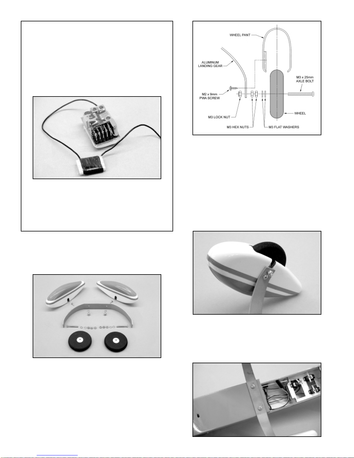
❑2) The Wheel Pants are now installed to the aluminum main
landing gear. Note that in side view, the landing gear is tapered
on one edge. The front or leading edge of the landing gear is the
untapered edge. Prepare the mounting holes in each wheel pant
by drilling a small diameter pilot hole (.052, #55 bit) through the
factory mark in the pant and the plywood pad inside. Mount the
pant to the landing gear using a 9mm PWA screw. Mount the
remaining pant in the same manner. After establishing the threads
with the mounting screws, we suggest removing the screws and
"hardening" the threads in each wheel pant with a small drop of
thin CA glue. After the glue sets, re-establish the threads once
again with the screws. This protects the threads from fuel damage
and makes them more resistant to stripping.
❑3) The main landing gear assembly is now mounted to the
bottom of the fuselage, using the two M3 x 10mm PWA bolts
and the two M3 Split Ring washers provided. It is highly
recommended that you first apply a small amount of non-
permanent thread locking compound, such as Loctite®#242
"Blue", to the bolt threads.
LANDING GEAR AND WHEEL PANTS:
From the kit contents, locate the bag containing the two Wheel
Pants and the bag containing the aluminum Main Landing Gear,
the Main Wheels, and the smaller bag of Mounting Hardware.
❑1) Slide one of the M3 x 2mm Axle Bolts through one of the
main wheels. One the other side of the wheel, slide two M3 Flat
Washers in place. Thread one of the M3 Hex Nuts in place almost
up to the wheel hub. Thread a second M3 Hex Nut in place up to
the first nut. Use pliers or a metric box end wrench to hold one of
the M3 nuts while firmly tightening the second nut to it - make sure
the wheel turns freely. Slide the exposed end of the M3 Axle Bolt
through the bottom hole in the aluminum Main Landing Gear.
Start to thread one of the M3 Lock Nuts onto the Axle Bolt. Hold
the nut firmly with pliers or a wrench and use a screwdriver to
tighten the axle bolt assembly firmly in place to the landing gear.
Repeat this process with the remaining wheel. 12
MODELER'S TIP (continued): We made our "bobbin" from a
piece of 3/32" x 3/4" x 1-1/4" balsawood. From the receiver,
measure the antenna out to 4-1/2" - no closer. This is the point
to start neatly wrapping the antenna wire around the bobbin. Do
not cross the wrapped antenna wire, simply lay it neatly next to
each strand. Wrapping the antenna wire 12 - 14 times around
a bobbin this size shortens its overall length by about 11". Hold
the now wrapped antenna wire to the bobbin with a length of
clear tape. Now when you install the receiver into the fuselage,
you will have a much more reasonable length of antenna wire to
work with at the rear.
What will this procedure do to the range of your receiver? The
answer is that you will lose some amount of range but not
enough to effect the overall safe operation of the model. This is
because a small R/C model is rarely flown to extreme distances
for the simple reason that you can no longer see it. Since you
would never do this, some loss of range is more than acceptable
for a small model.

allowing enough of the prop shaft threads to engage securely into
the engine. We replaced the stock prop/spinner with three Du-Bro
#8 Flat Washers. This allows the spinner to fit perfectly.
❑4) Before mounting the propeller to the engine, take the time
to make sure it is balanced. NEVER use an unbalanced propeller
on this or any model. Also, NEVER use a propeller that has been
previously damaged in any way.
The Spinner Assembly bag includes an aluminum adaptor ring,
specifically made for the Norvel™.074 engine. This adaptor ring
fits into the molded recess in the back face of the spinner base.
Insert the propeller shaft bolt - with the three washers in place -
through the propeller and the spinner back plate. Tighten the prop
bolt firmly to the engine, aligning the propeller with the upright
orientation spikes.
Press the spinner cone in place to the backplate, aligning it into
the recesses in the backplate. Secure the spinner in place firmly
using the two provided screws.
FINAL ENGINE SET-UP:
❑1) The Norvel™.074 R/C engine has an offset head idle stop
bolt installed into the left side of the carburetor body, just behind
the needle valve. This bolt is in place to limit the travel of the
throttle arm at low throttle.
We have found that if this bolt is completely removed, the throttle
lever is free to move further forward in low throttle movement with
the throttle servo. This means that an even lower idle speed can
be obtained. However, you must experiment a little to obtain the
lowest possible reliable idle speed, without killing the engine. Our
experience with this simple modification has given us very reliable
low speed idle characteristics and - after adjusting the trims on our
transmitter - even the ability to use the "Throttle Cut" feature,
available with some transmitters.
❑2) Now is the time to give some thought to the propeller that
you will use on your engine. We have used a variety of propellers
on our own Little Extra ARF models and have learned that
different brands all seem to have different prop shaft hole
diameters. For reference, the Norvel™.074 engine has a prop
shaft diameter of .157". Typical prop sizes for the Norvel™.074 are
6 x 4, 7 x 3, and 7 x 4. APC produces great props in these sizes
but they are produced with large diameter shaft holes. For
example, the APC 7 x 3 prop has a shaft hole measuring .185" in
diameter. Therefore, in order to use an APC 7 x 3 prop on our .074
engine, we used a 5/16" length of K&S 3/16" o.d. aluminum tubing
to "sleeve" the prop shaft hole down to the diameter that fits onto
the engine's prop shaft bolt.
Finally, some propeller brands come with shaft holes that are
smaller than the prop bolt. This requires that they be drilled out to
fit. For accuracy, always use a drill press.
❑3) With the Norvel™.074 engine, we found that in order to
mount both the propeller and the provided spinner onto the
engine, the aluminum prop/spinner that comes with these
engines, must be replaced. This is because it is too deep, not 13
Idle Limiting Bolt

place on the model. The liquid cleaner allows the decal to slide
easily into the desired position – do not press down on the decal.
Once in position, hold the decal lightly in place with your finger and
use a paper towel to gently dab the excess liquid away. Use a
small squeegee to now set the decal in place, removing all excess
liquid and any air bubbles. The SIG 4" Epoxy Spreader -
#SIGSH678 - is perfect for this job. Mop up any excess cleaner
with a dry cloth and allow the decals to set overnight. They will be
solidly adhered to the model without any air bubbles.
SETTING THE CONTROL SURFACE MOVEMENTS:
The following control movement information is provided for initial
set-up and test-flying purposes. After you have test-flown your
Little Extra and get a feel for how effective these movements are,
you can increase or decrease the movements as desired.
Ailerons: 1/2" Up - 1/2" Down
Elevators: 3/4" Up - 3/4" Down
Rudder: 1-1/8" Right - 1/1/8" Left
CENTER OF BALANCE:
IMPORTANT: The model is always balanced fully assembled with
the prop and spinner in place, the complete radio system installed,
and the fuel tank empty. As shown, we use a simple CG stand to
balance the model upside down, shifting as needed to get the
airplane level. The recommended starting CG for this model is
2-5/8" back from the leading edge of the wing at the fuselage side.
If needed, shift the battery pack to achieve the correct CG
location.
PRE-FLIGHT:
Before flying your Little Extra ARF, we strongly suggest that you
take the time to break-in your engine and adjust the idle for the
lowest possible reliable rpm's. The high quality of the piston-to-
cylinder fit on Norvel™engines makes break-in a must before
attempting to fly the model. Break the engine in per the factory
instructions and DO NOT use the molded plastic spinner provided
in this kit during break-in. We recommend that you use an electric
starter to start the engine the first few times, using the propeller
spinner/thrust washer provided with the engine. This avoids
burning the spinner with the electric starter during the break-in
process.
We use and highly recommend either SIG "Champion" 15% or
25% fuel for the Norvel™.074 R/C engines. These fuels both
contain generous oil content, absolutely essential for high-revving
smaller 1/2A engines.
❑5) The Norvel™.074 engine has an exhaust outlet that can be
positioned to any desired angle. We positioned ours to aim the
exhaust directly out of the right side of the fuselage and then
added a short length of large diameter fuel tubing to carry the
exhaust past the fuselage side. In actual practice, this works quite
well in keeping much of the exhaust residue off the model.
DECAL APPLICATION:
The decals supplied with your Little Extra ARF kit are high quality
Mylar®with an extremely aggressive adhesive. These are not
die-cut and must be individually removed from the sheet with a
hobby knife and a sharp #11 blade or with sharp scissors. For
placement, refer to the box art and various other photos. Note that
we have provided multiple "N" numbers that allow you to
personalize your model with your AMA number, etc.
We suggest the following method to accurately apply these
decals. Carefully cut out the decal with a hobby knife. Lift it
carefully off its sheet with tweezers. Use a product like SIG Pure
Magic Model Airplane Cleaner, Fantastic®, or Windex®to spray the
area of the model that will receive the decal. Then spray the
adhesive side of the decal as well. Lightly position the decal in
14

throttled back just enough to see a very slight descent. Smoothly
make the 180Oturn to set-up the upwind final approach to the
runway. Continue to throttle back as needed to land exactly where
you want. Again, the rudder is quite effective and should be used
to maintain the model's heading in relationship to the runway.
We sincerely hope that you will enjoy your Little Extra ARF model
for a long time to come. Please fly your model safely, with respect
to other flyers, spectators and property.
WARNING! THIS IS NOT A TOY!
Flying machines of any form, either model-size or full-size, are not toys!
Because of the speeds that airplanes must achieve in order to fly, they are
capable of causing serious bodily harm and property damage if they crash.
IT IS YOUR RESPONSIBILITY AND YOURS ALONE to assemble this
model airplane correctly according to the plans and instructions, to ground
test the finished model before each flight to make sure it is completely
airworthy, and to always fly your model in a safe location and in a safe
manner. The first test flights should only be made by an experienced R/C
flyer, familiar with high performance R/C aircraft.
The governing body for radio-control model airplanes in the United States
is the ACADEMY OF MODEL AERONAUTICS, commonly called the AMA.
The AMA SAFETY CODE provides guidelines for the safe operation of R/C
model airplanes. While AMA membership is not necessarily mandatory, it
is required by most R/C flying clubs in the U.S. and provides you with
important liability insurance in case your R/C model should ever cause
serious property damage or personal injury to someone else.
For more information contact:
ACADEMY OF MODEL AERONAUTICS
5161 East Memorial Drive
Muncie, IN 47302
Telephone: (765) 287-1256
AMA WEB SITE: www.modelaircraft.org
CUSTOMER SERVICE
SIG MANUFACTURING COMPANY, INC. is committed to your success in
both assembling and flying the Herr Little Extra ARF. Should you
encounter any problem building this kit or discover any missing or
damaged parts, please feel free to contact us by mail or telephone.
SIG MANUFACTURING COMPANY, INC.
401-7 South Front Street
Montezuma, IA 50171-0520
SIG MODELER’S ORDERLINE: 1-800-247-5008
(to order parts)
SIG MODELER’S HOTLINE: 1-641-623-0215
(for technical support)
SIG WEB SITE: www.sigmfg.com
LIMIT OF LIABILITY
The craftsmanship, attention to detail and actions of the builder/flyer of this
model airplane kit will ultimately determine the airworthiness, flight
performance, and safety of the finished model. SIG MFG. CO.’s obligation
shall be to replace those parts of the kit proven to be defective or missing.
The user shall determine the suitability of the product for his or her
intended use and shall assume all risk and liability in connection therewith.
15
Finally, always make sure your transmitter and airborne battery
packs are fully charged before heading to the flying field!
FLYING:
If you have followed the instructions in this manual carefully, flying
your Little Extra ARF should be a lot of fun! We suggest choosing
a calm day for test-flying this model. Such conditions are always
best for evaluating and trimming R/C aircraft, especially smaller
models. We also strongly suggest that you perform a complete
range check of your radio system - with and without the engine
running. Radio system problems will not magically disappear
once you're in the air!
We suggest that you take this model off from the ground (Rise Off
Ground). While it might be possible to hand-launch this design, its
low wing configuration makes this awkward. This is a small model
and therefore has small wheels. So it is obviously best to take off
and land from a relatively smooth surface, such as asphalt,
concrete, or smooth dirt. Taking off of a grass field may be doable
but it would have to be very close-cut grass to allow this to
happen.
Before starting your engine, carefully check all control movements
with you transmitter. Start the engine and adjust the needle valve
for peak rpm's. Taxi the airplane out to the runway and turn it
directly into the wind. Throttle up the engine slowly, while gaining
speed, keeping it pointed into the wind with small amounts of
rudder input as needed. Flying speed will be very quickly reached
and only a small amount of elevator will be needed to become
airborne. Climb to a reasonable altitude before beginning to trim
the model. This airplane has a fully symmetrical airfoil and should
therefore be trimmed for straight and level flight while at full
throttle.
After trimming the airplane, start making a few turns to become
comfortable with the way the airplane responds. This is NOT a
beginner's airplane and was specifically designed to respond
quickly to control inputs - keep this in mind, especially at lower
altitudes! Climb back up to altitude and throttle back the engine to
become familiar with the airplane's low speed characteristics. You
should find that it will fly very slowly at low throttle settings,
especially if you keep the nose level or slightly up with a little up
elevator input. This is also a good time to become familiar with the
stall characteristics. Our Little Extra ARF prototypes have all
displayed a straight-forward stall with almost instant recovery to
controlled flight. All of this is great information to have when it
comes time to set up your first landing.
Once you're more comfortable with the airplane and how it
responds at various throttle settings, you can begin to explore the
flight envelope of this great little model. Start with a simple loop or
two. Next, try a little inverted flight. You should find that the Little
Extra is comfortable in inverted flight, needing only a small amount
of up elevator to keep the nose up. Try a few aileron rolls to get a
feel for the roll rate. Remember that you have likely set your
airplane up with the suggested initial control throw movements -
these can be changed later to suit your particular preferences.
You will also find that the Little Extra spins very nicely and will exit
the spin almost instantaneously after releasing the controls. We
have managed some very respectable "flat spins" with this model
as well.
When it comes time to land, you should find that it is almost a
non-event with the Little Extra! To set-up a proper landing, use the
standard downwind leg approach to the end of the runway,

16
HERR LITTLE EXTRA LOG BOOK
Date of first flight:
Comments:
Table of contents


