Herrmidifier Herrtronic RDU-D Owner's manual
Engineered Humidification Systems
Herrmidifier®| www.herrmidifier-hvac.com
Herrtronic®RDU-D
Supplemental Manual

Herrtronic®RDU-D Supplement
Installation, Operation, & Maintenance Manual
2www.herrmidifier-hvac.com
TABLE OF CONTENTS
I. Warranty Information................................................................................................................................3
II. General Description..................................................................................................................................3
Mounting Option ..................................................................................................................................3
Accessory Bag Contents .....................................................................................................................4
RDU-D Dimensions .............................................................................................................................4
III. Installation Preparation.............................................................................................................................4
Unit Clearances...................................................................................................................................4
IV. Direct Mount Option ..................................................................................................................................5
MDS with Direct Mount RDU...............................................................................................................5
MDD with Direct Mount RDU...............................................................................................................5
V. Remote Mount Option ................................................................................................................................6
MDS with Remote RDU.......................................................................................................................6
MDD with Remote RDU.......................................................................................................................7
VI. RDU Operation..........................................................................................................................................7
Steam Plume Chart .............................................................................................................................7
VII. Troubleshooting Chart...............................................................................................................................8
VIII. Parts List...................................................................................................................................................9
Exploded View.......................................................................................................................................9
IX. Wiring Diagrams........................................................................................................................................10
RDU-D with Transformer 460/600V. ....................................................................................................10
RDU-D with Transformer 380V. ...........................................................................................................11
RDU-D without Transformer ................................................................................................................12
MDS/MDM Control to (2) RDU-D Units ...............................................................................................13

Herrtronic®RDU-D Supplement
Installation, Operation, & Maintenance Manual
3
www.herrmidifier-hvac.com
I. LIMITED WARRANTY
Seller warrants the equipment of its manufacturing to
be free from defects in workmanship and material for a
period of 24 months after shipment. This warranty is
limited, however, to the repair or replacement of defective
equipment, which is returned, freight prepaid, to Seller’s
factory.
This limited warranty does not apply to any part or
component that is damaged in transit or when handling,
has been subject to misuse, negligence or accident, has
not been installed, operated or serviced according to
Seller’s instructions, or has been operated beyond the
factory-rated capacity or has been altered in any way.
Seller’s liability is limited to replacement of defective parts
or components and does not include any cost of labor
(including, but not limited to, labor required to remove and/
or reinstall any defective part) other than Trion/Herrmidier
factory labor.
Trion/Herrmidier shall not be responsible for loss of use
of any product, loss of time, inconvenience, or damage
to other equipment, or any other indirect or consequential
damage with respect to property whether as a result of
breach of warranty, neglect, or otherwise.
THE WARRANTIES AND LIABILITIES SET FORTH ARE
IN LIEU OF ALL OTHER WARRANTIES AND
LIABILITIES, EXPRESSED OR IMPLIED, IN LAW OR
IN FACT, INCLUDING IMPLIED WARRANTIES OF
MERCHANTABILITY AND FITNESS FORPARTICULAR
PURPOSE.
The foregoing shall constitute the total liability of seller
in the case of defective performance of all or any of the
equipment or services provided to Buyer. Buyer agrees
to accept and hereby accepts the foregoing as the sole
and exclusive remedy for any breach or alleged breach of
warranty by Seller.
II. GENERAL DESCRIPTION
The RDU-D Series Room Distribution Units are designed
as a companion module for all MD Series Herrtronic
humidiers.
The RDU may be directly mounted on top of the Herrtronic
cabinet or mounted remotely. The RDU consists of a fan,
controls, & steam hose to distribute the steam directly into
the space. RDU-D must he remotely mounted when used
with an MDM series humidier.
Figure 1 - Mounting Options
Model No Electrical
Characteristics Capacity
RDU-D-1 208-240-1-50/60 5-50 lbs/hr.
RDU-D-1T 480-600-1-50/60
RDU-D-2 208-240-1-50/60 60-100 lbs/hr.
RDU-D-2T 480-600-1-50/60
RDU-D-2R 208-240-1-50/60
110-250 lbs/hr.
RDU-D-2L 208-240-1-50/60
RDU-D-2TR 480-600-1-50/60
RDU-D-2TL 480-600-1-50/60
Note: 1T & 2T models include a transformer to provide
208/230 single phase power to the RDU.
Note: MDD Units require two RDU units. For Direct
Mount you must use a specic right and left mount unit.
For remote mount, two Identical units may be used.
For remote mounting applications, the plumbing and
electrical connections may be routed through the bottom
or back of the RDU. There are two electrical knockouts,
two steam supply knockouts and one condensate return
knockout on both the bottom and back to facilitate
installation.
Herrtronic®RDU-D Supplement
Installation, Operation, & Maintenance Manual
4www.herrmidifier-hvac.com
As shipped, the RDU is set up for direct unit mounting.
Longer wiring and condensate return tubing (supplied) will
be required for remote mounting. Be sure to use 18 gauge
(minimum) copper conductor wire with insulation rated for
600 VAC. Supply power may originate from the Herrtronic
humidier or a separate supply. If a separate source is
used, be sure to install a dedicated power disconnect.
All hardware and accessory components required for
installation are included as listed below:
Accessory Bag Contents
Item Quantity
¾” I.D. Plastic bushing 2
3” Diameter plastic hole plug 2
5/16” I.D. Plastic bushing 1
Steam inlet union 1*
2 ½” Stainless steel hose clamp 1*
¼” x 2” Lag screw 2
#8–32 x 3/8” Stainless steel machine screw 4
Wiring Kit 1
¼” O.D. Condensate return tubing 10’
*-Double quantity for RDU-D-2 series units
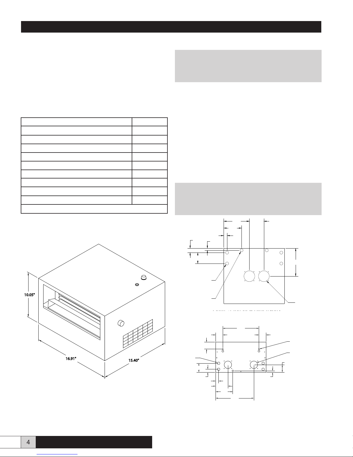
Figure 2 - Overall Dimensions
III. INSTALLATION PREPARATION
! WARNING !
Disconnect power to the humidier while
installing RDU.
The RDU unit must either be placed higher than the
Herrtronic unit or provisions for handling the condensate
via an external drain must be made. The following chart
details the physical clearances around the cabinet for
servicing the unit. Figure 13 details the clearances required
due to the steam plume.
MINIMUM CLEARANCES AROUND CABINET
LEFT - 15”
RIGHT - 15”
TOP* - 2”
BOTTOM - 0”
* Subject to output, fan speed and room conditions
NOTE:
The steam plume should not impinge on walls,
ceilings or other objects. Supply air registers, if
present, must be directed away from RDU.
Figure 3 - Bottom View Dimensions
Figure 4 - Back View Dimensions
10.05"
16.91" 15.40"
Figure 3 Top View Dimensions
.99"
4.99"
7.13" 4.00"
7.70"
1.20"
3.00"
.56"
(4) 7/8" Holes
Power Access
(2) 7/8" Holes
Optional Condensate Drain
(2) 3" Holes
Steam Hose Inlet
Figure 4 - Bottom View
Front of Unit
2.45"
12.00"
2.45"
2.30"
(4) 7/8" Knockouts
Power Access
3.00"
1.00"
.99"
5.77"
.50"
2.50"
(2) 2 1/2" Holes
Optional Steam Inlets
(2) 5/16 X 5/8 Dia.
Keyhole Mounting Slots
Figure 5 - Back View
4.14"
12.76"

Herrtronic®RDU-D Supplement
Installation, Operation, & Maintenance Manual
5
www.herrmidifier-hvac.com
REMOVE THE COVER FROM THE RDU
1. Loosen the two hex socket head set screws on the fan
speed control knob and remove knob (Figure 5).
2. Remove the phillips head screws which fasten the
cover to the housing.
IV. DIRECT MOUNT OPTION (MDS, MDD)(Figure 6 & 7)
! WARNING!
Be sure to disconnect power to the Herrtronic
Humidier before beginning installation.
1. Assure that the mounting for the Herrtronic unit will
support the additional 40 pound load of each RDU
unit.
2. Remove the knock-out from the top of the Herrtronic
cabinet and install the 5/16” I.D. plastic bushing for the
condensate return.
3. Remove the rearmost 7/8” knockout from the top of
the Herrtronic cabinet.
4. Install one 3/4” plasitc bushing from the inside into the
rearmost 7/8” hole in the bottom of the RDU.
5. Place the RDU on the Herrtronic cabinet, guiding the
steam hose(s) into the tank compartment.
6. Feed the wires (total of seven) through the 3/4” bushing
and condensate tubing through the 5/16” bushing into
the Herrtronic unit.
7. Fasten the RDU in place using four #8-32 self-tapping
screws installed from inside the Herrtronic cabinet.
8. Replace the RDU cover & fan speed control knob.
9. Insert the condensate return tubing into the grey
plastic ll tee. It will extend I” into the tee.
10. Connect wires # 1 -6 to the 6 pole RDU terminal strip
located near the top of the Herrtronic high voltage
electrical compartment. Connect the ground wire #24
to the Herrtronic ground terminal located near the
bottom of the high voltage compartment.
NOTE
See Figure 15, 16 & 17 for standard electrical hookup
for MDM and MDS.
11. Remove jumper wire #39 from the Herrtronic 12
pole controls terminal strip located in the low voltage
electrical compartment between poles #1 and #2.
Installation is now complete. Proceed to the RDU Operation
section of this manual then to the Start-Up section of the
Herrtronic Installation and Operation Manual OM-93.
Figure 6 - MDS Direct Mount
Figure 7 - MDD Direct Mount
ENTERFAULTS
HERRTRONIC MD
ON/OFF
CYL FULL
BACK
FAULTPOWER
HERRMIDIFIER
HERRMIDIFIER
HERRMIDIFIER
HERRMIDIFIER
HERRMIDIFIER
SLAVE
FAULTPOWER
BACK
ENTER
FAULTS
ON/OFF
CYL FULL
MASTER
FAULTPOWER
BACK
ENTER
ON/OFF
FAULTS
CYL FULL
HERRTRONIC MD
PHILLIPS HEAD SCREWS
(6) PER SIDE
(1) ON FRONT
SIDE
Fan Speed Control Knob
Figure 5

Herrtronic®RDU-D Supplement
Installation, Operation, & Maintenance Manual
6www.herrmidifier-hvac.com
V. REMOTE MOUNT OPTION (MDM, MDS, MDD)
1. The RDU may hang directly on a wall using the two
1/4” x 2” lag screws included. There are two key-hole
slots on the back of the cabinet which engage these
screws. Be certain that: 1) the screws are fastened
securely enough to the wall to support the 40 lbs.
weight of each RDU unit, and 2) the screws are level.
Turn the screws in until the heads are 1/8” away from
the mounting surface.
2. Hang the unit on the wall and tighten the two lag
screws.
3. The steam hose(s) is to be connected using the steam
inlet union(s) (Figure 8).
4. Trim the steam hose(s) which is connected to the RDU
manifold so that it ts properly onto the union(s) and
secure connections with a hose clamp(s).
5. Fasten steam inlet union(s) to bottom or back of RDU
cabinet with screws.
6. Remove the knockout from the top of the Herrtronic
cabinet and install the 5/16” I.D. plastic bushing
(included).
7. Remove the 18” piece of condensate return tubing
connected to the manifold elbow.
8. Uncoil the 10’ piece of condensate return tubing (drain
line), feed into the RDU cabinet, from the bottom or
back, and connect to the manifold elbow.
9. Run the condensate return tubing down into the
Herrtronic cabinet through the 5/16” I.D. plastic
bushing.
10. The condensate tubing can be attached to the steam
hose or electrical conduit interconnecting the RDU
and Herrtronic with cable ties or equivalent.
11. After the condensate tubing is secured, insuring that
there are no kinks or low spots, the length should be
trimmed so that it can extend 1” into the grey plastic ll
tee in the Herrtronic unit.
12. National, state or local electrical codes may require
the use of two separate conduits - one for high voltage
supply power and one for control wiring.
13. There are a total of seven wires which are to be
connected between the RDU and the Herrtronic unit.
The RDU receives all of its power and control from the
Herrtronic unit. Use the two 7/8” holes or knockouts
on the bottom or back of the RDU cabinet and the two
7/8” knockouts on the top of the Herrtronic cabinet for
wiring conduit.
14. Wires #3 and #4 are the high voltage power supply
and should be run in one conduit.
15. Along with the ground wire #24, wires #1, #2, #5, and
#6 should be run in the second conduit.
16. Connect wires # 1-6 to the 6 pole RDU terminal strip
located near the top of the Herrtronic high voltage
electrical compartment. Connect the ground wire #24
to the Herrtronic ground terminal located near the
bottom of the high voltage compartment.
NOTE
See Figure 15, 16 & 17 for standard electrical hookup
for MDM and MDS.
17. Remove jumper wire #39 from the Herrtronic 12
pole controls terminal strip located in the low voltage
electrical compartment between poles #1 and #2.
18. Replace the RDU cover and the fan speed control
knob.
Installation is now complete. Proceed to the RDU operation
section then to the start-up section of the Herrtronic
Installation, Operations and Service Manual OM-93.
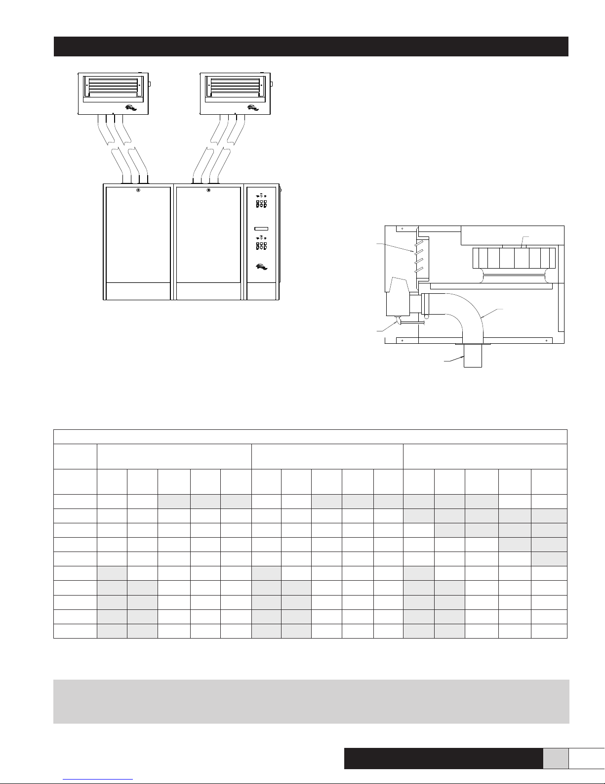
Figure 8 - Steam Connections (Side View)
Figure 9 - Drain Line (Front View)
Figure 10 - MDS Remote Mount
BLOWER
DRAIN
LINE
STEAM HOSE
STEAM INLET UNION
(REMOTE MOUNT)
STEAM INLET UNION
(ALTERNATE LOCATION)
DRAIN
LINE
GRILL
>50 lb/hr requires second hose
CYLFULL POWER FAULT
BACK
ON/OFF
FAULTS ENTER
HERRTRONIC MD
Figure 10 - Front View
Herrtronic®RDU-D Supplement
Installation, Operation, & Maintenance Manual
7
www.herrmidifier-hvac.com
Figure 11 - MDD Remote Mount
VI. RDU OPERATION
Upon starting the Herrtronic unit, the RDU fan will be
energized. If airow is not sensed within ten seconds, the
Herrtronic unit will shutdown and a fault will be registered.
Depress ‘”Fault” button to conrm fault condition and clear
fault by pressing “Enter” and then “Back” button to return
to Menu 1.
Once operating, the fan speed can be adjusted continuously
from 1—5 (slow—fast) by turning the fan speed control
knob. Refer to the chart below for the optimum fan speed
setting for your application.
When the Herrtronic unit is turned “off”, either by switch
or controller, the RDU fan will continue to operate for 15
minutes to prevent the formation of condensate inside the
cabinet. The steam plume direction can be controlled both
horizontally and vertically by adjusting the louvers on the
air discharge grille.Louvers adjusted as shown in Figure
12 produce the most consistent and shortest evaporation
distance.
Figure 12 - Louver Details
Figure 11 - MDD Remote Mount
HERRTRONIC MD
STEAM INLET UNION
(REMOTE MOUNT)
STEAM HOSE
DRAIN
LINE
BLOWER
OPTIMUM LOUVER
DIRECTION, DOWN 30°
Figure 14 - Optimum Louver Placement
Figure 13 - Steam Plume Characteristics
! WARNING!
To avoid potential contact with steam, be certain to shut off the Herrtronic unit BEFORE
adjusting the louvers.
STEAM PLUME (@75° F, 55% R.H.)
Output
lbs./Hr
Throw (in.)
Blower Speed (CFM)
Breadth (in.)
Blower Speed (CFM)
Rise (in.)
Blower Speed (CFM)
1
(210)
2
(240)
3
(280)
4
(320)
5
(365)
1
(210)
2
(240)
3
(280)
4
(320)
5
(365)
1
(210)
2
(240)
3
(280)
4
(320)
5
(365)
10 20 15 15 15
20 50 35 30 35 35 20 20 18 18 18
30 90 80 75 70 60 28 26 24 24 24 10
40 98 92 90 94 100 36 36 36 32 26 18 12 6
50 112 112 116 120 120 40 36 36 36 30 36 22 12 6
60 120 126 130 134 36 34 28 28 58 30 14 6
70 126 132 138 42 40 36 36 20 12
80 130 138 156 48 42 40 52 24 16
90 136 144 156 58 52 46 72 36 20
100 126 138 156 60 60 48 120 50 25

Herrtronic®RDU-D Supplement
Installation, Operation, & Maintenance Manual
8www.herrmidifier-hvac.com
VII. TROUBLESHOOTING
Problem/Symptom Reason / Correction
Steam Condensing on RDU sheetmetal or other objects. 1. Adjust louvers per gure 12
2. Fan not running. Check pressure switch for fail closed
condition. Herrtronic unit should not operate if fan is not
running.
3. Too little airow. Increase fan speed.
4. Room is very cold, very humid, or objects are cold.
Decrease humidity setpoint at Herrtronic unit or humidity
controller.
Fan not energizing 1. Check that the fan rotates freely.
2. Check fuses in RDU.
3. Check wiring to fan.
4. Check voltage to fan - should be 220 VAC +/- 10%.
5. Replace fan and capacitor.
Fan speed adjustment not working. 1. Replace rheostat.
Water spitting out of manifold 1. Check condensate drain hose. If it is clogged, clean.
2. Make sure condensate drain hose is sloped properly
and there are no low spots or kinks.
Fan does not continue to operate for 15 minutes after
Herrtronic unit shuts down.
1. Check wiring to relay/timer.
2. Check that the 24 VAC is present between terminal #2
and #3 on relay timer. If so, replace timer.
Air pressure switch not closing. 1. Fan speed setting too low. Increase fan speed.
2. Check tubing on switch for clogging or out of position.
3. Faulty air pressure switch. Replace.
Blown fuses in RDU 1. Check fan for short circuit.
2. Check RDU wiring for short circuit.
Herrtronic®RDU-D Supplement
Installation, Operation, & Maintenance Manual
9
www.herrmidifier-hvac.com
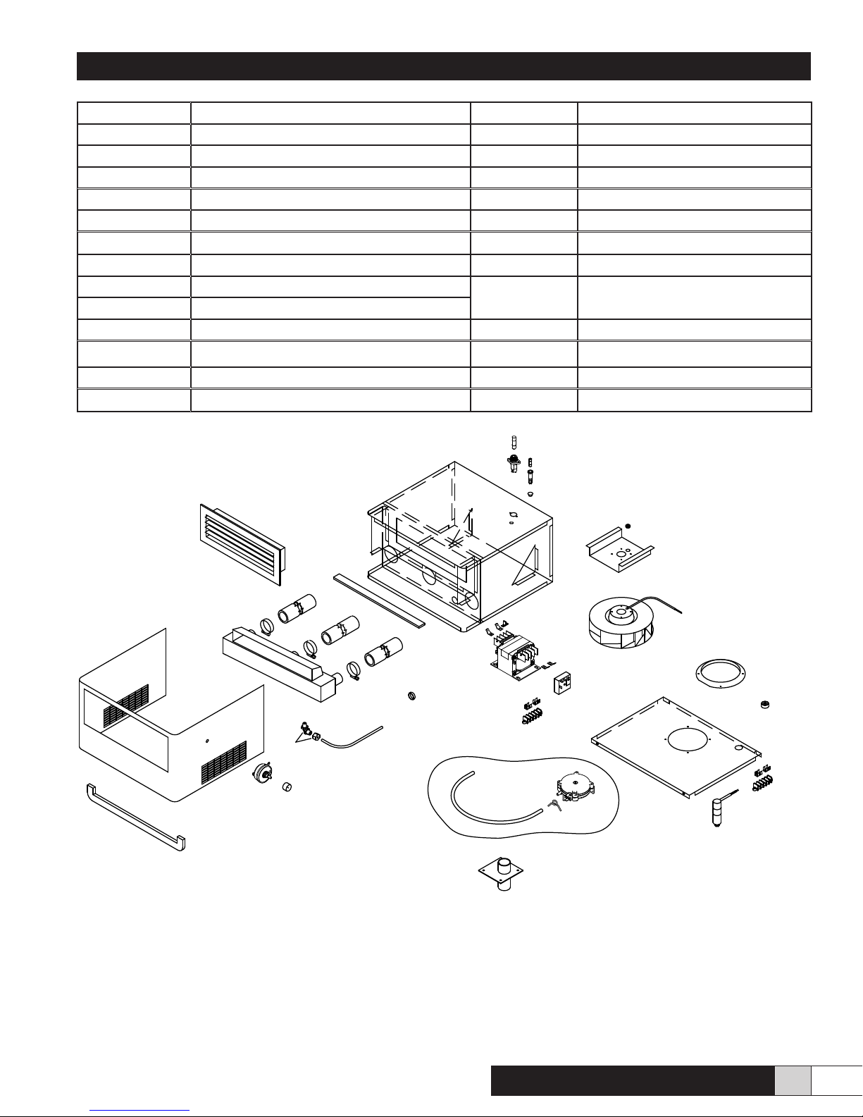
1847C Quick Connects EST-1404 Rheostat
120096-006 Hole Plug EST-1405 Relay Timer
165475-001 Dierential Pressure Switch Kit EST-1407 Blower Speed Control Knob
165538-001 Fuse, 8/10 A EST-1408 Capacitor
265544-001 Fuseholder EST-1409 Bushing
265561-001 Transformer (RDU-D-1T & 2T) for 480/600 EST-1415 1/4” Tubing
265561-002 Transformer (RDU-D-1T & 2T) for 380 EST-1416 Fuseholder
DH-052 Foam Tape EST-1417 Fuse, 1 A
EST-230 Steam Hose EST-1447-1
EST-1447-2
Manifold Assembly (Specify Unit
Model Number)
EST-353 Bushing
EST-531 5-Pole Terminal Rail EST-1458 Steam Inlet Union
EST-1401 Distribution Grille EST-1538 Rubber Grommet
EST-1402 Blower EST-1563 Stainless Steel Hose Clamp
EST-1403 Blower Inlet Ring GT-20-20 Elbow
EST-1409
EST-353
EST-1402
EST-1403
EST-1408
EST-531
1847C
165475-001
EST-1405
EST-531
1847C
EST-1416
EST-1417
120096-006
EST-1401
DH-052
EST-1407
EST-1415
GT-20-20
EST-230
EST-1563
EST-1447
DH-052
165538-001
265544-001
265561
EST-1404
EST-1538
EST-1458
Figure 14 - Exploded View

Herrtronic®RDU-D Supplement
Installation, Operation, & Maintenance Manual
10 www.herrmidifier-hvac.com
H2 FOR 460V INPUT
H3 FOR 600V INPUT
Figure 15 - RDU-D with 460/600V Transformer

Herrtronic®RDU-D Supplement
Installation, Operation, & Maintenance Manual
11
www.herrmidifier-hvac.com
Figure 16 - RDU-D with 380V Transformer

Herrtronic®RDU-D Supplement
Installation, Operation, & Maintenance Manual
12 www.herrmidifier-hvac.com
Figure 17 - RDU-D w/o Transformer
Herrtronic®RDU-D Supplement
Installation, Operation, & Maintenance Manual
13
www.herrmidifier-hvac.com
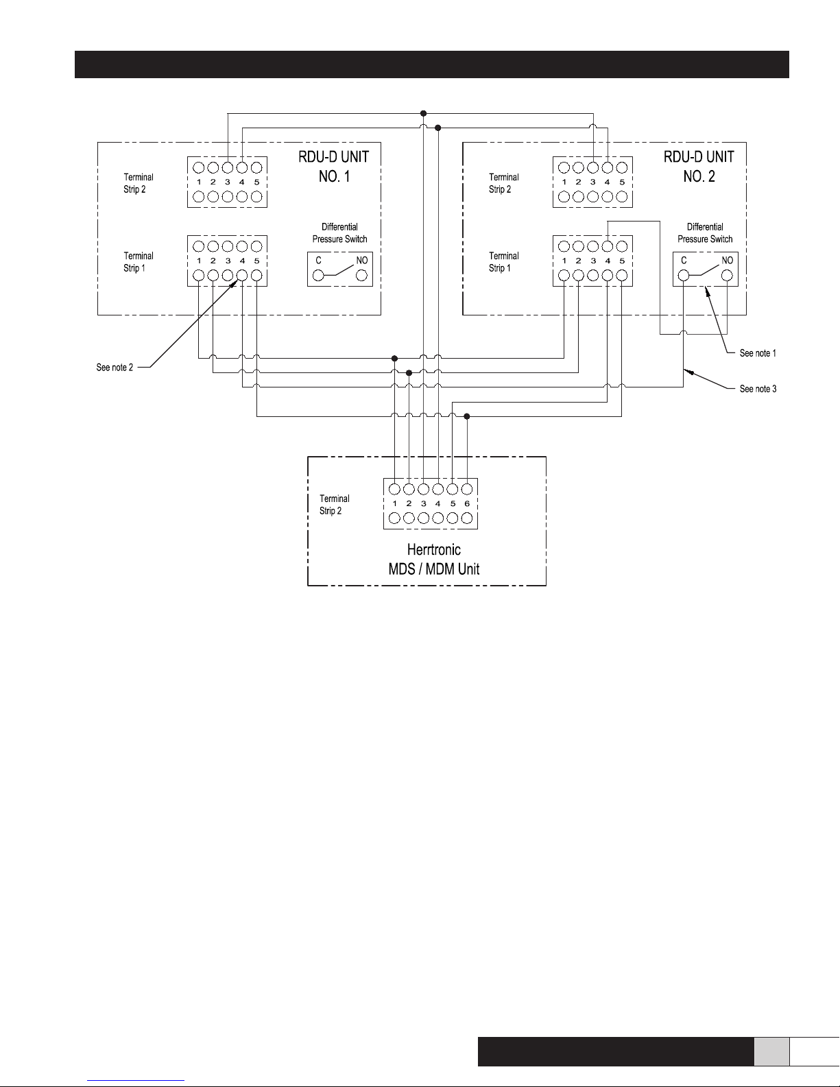
Figure 18 - MDS/MDM Control to (2) RDU-D Units
Notes:
1. Disconnect wire number (16) from the common terminal of the differential pressure switch in the RDU-D unit
number (2). Remove the spade connector and cap with a wire nut.
2. Disconnect Blue wire number (5) from terminal strip number (1) on RDU-D unit number (1) remove the spade
connector and cap with a wire nut.
3. This wire is connected to RDU-D unit number (1) at terminal strip number (1). Position number (4) to the
RDU-D number (2) common terminal of the differential pressure switch.

Engineered Humidification Systems
Form No. OM-102 09/13 ©Herrmidier 2013. All Rights Reserved.
Herrmidifier®
101 McNeill Rd. | Sanford, NC 27330
Table of contents
Other Herrmidifier Humidifier manuals

Herrmidifier
Herrmidifier 6000 Series User manual

Herrmidifier
Herrmidifier G-200/300 Owner's manual

Herrmidifier
Herrmidifier 465-C1 Manual

Herrmidifier
Herrmidifier Herrmidisteam-SS User manual

Herrmidifier
Herrmidifier Herrtronic AD User manual

Herrmidifier
Herrmidifier 2000 User manual

Herrmidifier
Herrmidifier G-100ES Owner's manual

Herrmidifier
Herrmidifier 707U Manual

Herrmidifier
Herrmidifier Herrdraulic User manual

Herrmidifier
Herrmidifier Herrtronic 6500 Series User manual


