manuals.online logo
Brands
  1. Home
  2. •
  3. Brands
  4. •
  5. Profelmnet
  6. •
  7. Control Panel
  8. •
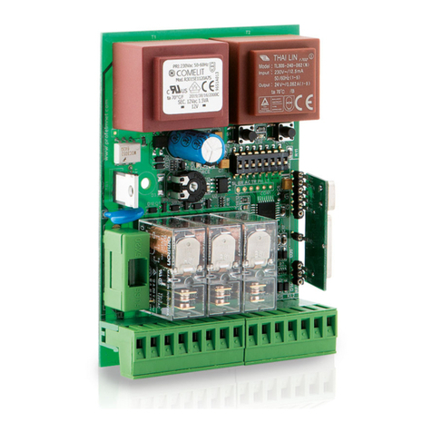
  9. Profelmnet 3033 User manual

Profelmnet 3033 User manual

Ag.Dimitriou 286A ,173 42 Agios Dimitrios
Call center: 210 9850 244, Fax: 210 9823 264
www.profelmnet.com
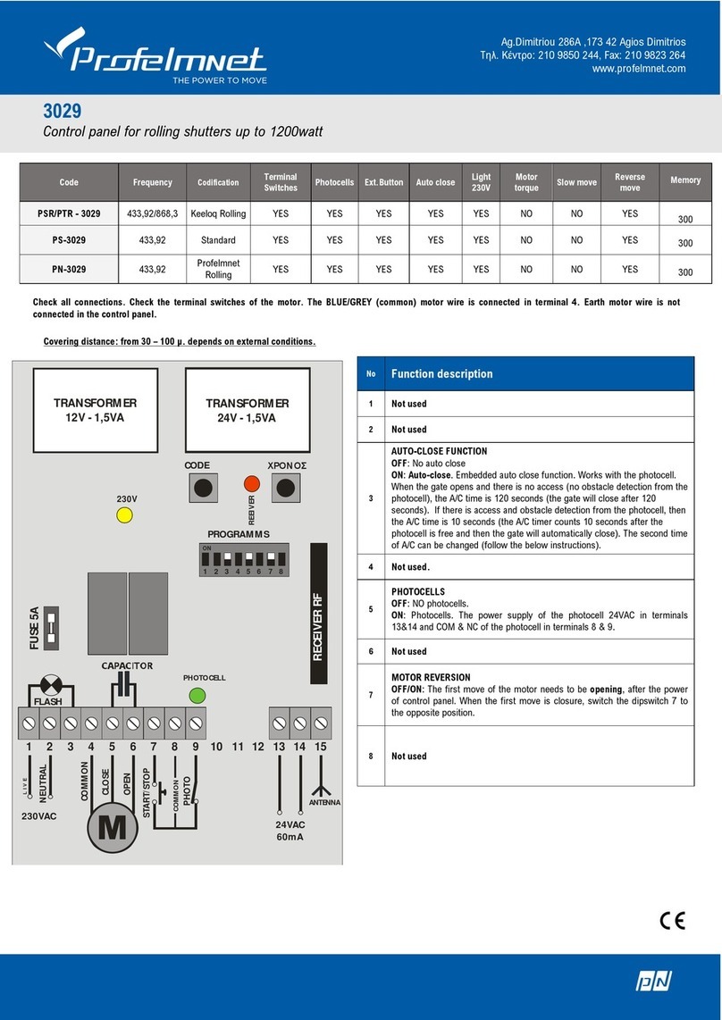
3033
Control panel for sliding gate –single swing gate- barrier
Μετασχηματιστής
12V - 1,5VA
Μετασχηματιστής
24V - 1,5VA
ΠΥΚΝΩΤΗΣ
FUSE 5Α
ΠΡΟΓΡΑΜΜΑΤΑ
1 2 3 4 5 6 7 8
ON
ΔΕΚΤΗΣ RF
1 2 3 4 5 6 7 8 9 10 11 12 13 14 15
ΦΑΡΟΣ
Φώτο Τερματικοί
M
ΦΑΣΗ
ΟΥΔΕΤΕΡΟΣ
ΚΟΙΝΟ (μπλε)
START/STOP
ΦΩΤΟ
Κεραία
ΑΝΟΙΓΜΑ
ΚΛΕΙΣΙΜΟ
230VAC 24VAC
60mA
ΚΛΕΙΣΙΜΟ
ΑΝΟΙΓΜΑ
ΚΟΙΝΟ
Τερματικοί
διακόπτες
ΚΟΙΝΟ
230V
+
ΡΥΘΜΙΣΗ
ΔΥΝΑΜΗΣ
ΜΟΤΕΡ
ΚΩΔΙΚΟΣ ΧΡΟΝΟΣ
ΔΕΚΤΗΣ
Code
Frequency
Codification
Terminal
Switches
Photoce
lls
Ext.Button
Auto
close
Light
230V
Motor
torque
Slow
move
Reverse
move
Memory
PSR/PTR - 2033
433,92/868,3
Keeloq
Rolling
YES
YES
YES
YES
YES
YES
YES
YES
300
PS-3033
433,92
Standard
YES
YES
YES
YES
YES
YES
YES
YES
300
PSR/PTR-3033P
433,92/868,3
Profelmnet
Rolling
YES
YES
YES
YES
YES
YES
YES
YES
300
Νο
Function description
1
OFF: NO slow move
ON: With slow move, that starts 2SEC before the end-route of the
door and continues for 40SEC or until the terminal switches is
blocked.
2
OFF: No motor brake
ON: Brake when the gate reaches the end of the route. This
function works with the function the slow move.
3
OFF: No auto close
ON: Auto-close. There is a double counter in the A/C function.
The first one is 120 seconds and is applied when the door stops
after an open function. During this counting time of 120 sec., if
the photocell beam is disturbed, then after the beam is free, the
A/C counting time becomes 10 sec. until the fully closed position.
4
OFF: NO terminal switches. In case of single swing gate or rolling
shutter.
ON: Terminal switches. In case of sliding gate or barrier.
5
OFF: NO photocells.
ON: Photocells. The power supply of the photocell 24VAC in
terminal 13&14 and COM & NC of the photocell in terminal 8 & 9
6
OFF: Adjust motor torque during the whole route of the gate.
ON: Adjust motor torque during the slow move only. It is
recommended for heavy motors.
7
OFF/ON: The first move of the motor needs to be opening, after
the power of control panel. When the first move is closure, switch
the dipswitch 7 to the other position.
8
OFF: FLASH. The terminals 1 & 3 give 230VAC/5A for how long the
gate is working.
ON: LIGHT. The terminals 1 & 3 give constant power 230VAC for 2
minutes every time that gate changes direction.
Check all connections. Check the terminal switches of the motor. The BLUE/GREY motor wire is connected in terminal 4.
Ag.Dimitriou 286A ,173 42 Agios Dimitrios
Call center: 210 9850 244, Fax: 210 9823 264
www.profelmnet.com
Functions and connections
Power supply 230V:
Supply the control panel with
230V.Check that the yellow
indication light is ON. Press the
button of the transmitter and
check the red indication light is
ON. The first shutter move
after power-up (230V) is the
OPEN direction, otherwise
substitute open/close motor
wires.
Clear memory:
The first step is to clear the rolling code memory. Press the button
CODE of the controller and the RED light goes ON after a while.
Keep it pressed until the light goes off. The memory is now clear.
Adding a new transmitter with the controller
button:
Press the CODE button and the RED light goes on (after a small
delay). Leave it and during the next 3 seconds, press the desired
transmitter channel button until the RED light blinks and goes OFF.
The new transmitter is saved. Follow the same procedure to
program more new transmitters.
Working time:
Adjustable from 1-180S. While the gate is fully closed, press and
keep the TIMER button of the controller pressed until the shutter
fully open position. Then leave it. The working time is saved.
Adjustable motor torque:
The motor torque is controlled by the dipswitch 6. To adjust the
motor torque for the whole gates’ route, place the dipswitch 6 on
OFF position. Then, adjust the motor torque in the middle and
check the gate. If auto close is ON, but the motor has not slow
move, place the dipswitch 6 on ON position and adjust the torque
of the slow move. Photocells are necessary.
Adding a new transmitter remotely:
The motor is stopped. Press a working transmitter button (already
in memory) to start the motor working and hold it pressed until the
motor stops. When it stops, leave it and press the new transmitter
button immediately. The new transmitter is saved. Repeat steps to
program more transmitters remotely. When the memory is full
(300 transmitters) you cannot add more new transmitters.
Pedestrian function:
When the door opens in order the pedestrian traverses the gate,
the gate will open for a while and then automatically will close.
Photocells need to be installed.
Photocell connection:
Connect the photocell contact and power supply 24VAC according
to the diagram in the right.
When you finish, remove the
jumper PHO to activate the
photocell contact. In case of
failure, put back the jumper
and recheck connections.
Photocell operation:
When the door closes and the
photocell beam is cut-off, the
door stops immediately and
automatically activates the open function. If the photocell beam is
cut-off, the door never closes.
Adjusting the auto close time:
There is a double counter in the A/C function. The first one is 120
seconds and is applied when the door stops after an open function.
During this counting time of 120 sec., if the photocell beam is
disturbed, then after the beam is free, the A/C counting time
becomes 10 sec. until the fully closed position. In 3033, the second
counting time of 10 sec. , can be regulated. Press the timer
button, keep it pressed and within 1 sec. , press the code
button. The red indicating LED starts flashing, indicating the
seconds of the counter. The time of the counter is from 1-120
seconds. The dipswitch 3 needs to be ON.
Indication light LED:
There are indication LED lights that displays the different functions
of the control panel.
Reset the automation:
Case of malfunction, please remove the power supply (230Vac) for
10 seconds, reconnect and recheck.
Compatible transmitters:
Based on the model you have, select the appropriate transmitter.
Other Profelmnet Control Panel manuals

Profelmnet 2114 User manual

Profelmnet

Profelmnet 2114 User manual

Profelmnet 3433 User manual

Profelmnet

Profelmnet 3433 User manual

Profelmnet 3029 User manual

Profelmnet

Profelmnet 3029 User manual

Profelmnet 3029 User manual

Profelmnet

Profelmnet 3029 User manual

Profelmnet 3033 User manual

Profelmnet

Profelmnet 3033 User manual

Popular Control Panel manuals by other brands

NAPCO Gemini GEM-P9600 Programming instructions

NAPCO

NAPCO Gemini GEM-P9600 Programming instructions

MOOSE Z950 manual 

MOOSE

MOOSE Z950 manual 

ESAB Aristo U6 instruction manual

ESAB

ESAB Aristo U6 instruction manual

Erone EACP105E installation manual

Erone

Erone EACP105E installation manual

Steamist TSC-250 Installation and operating instructions

Steamist

Steamist TSC-250 Installation and operating instructions

Vetus XTPAN252A manual

Vetus

Vetus XTPAN252A manual

Johnson Controls Frick QUANTUM LX manual

Johnson Controls

Johnson Controls Frick QUANTUM LX manual

Balboa TP200 PANEL user guide

Balboa

Balboa TP200 PANEL user guide

Bosch D9412GV3 Operation and installation guide

Bosch

Bosch D9412GV3 Operation and installation guide

SOMFY animeo Solo 2 zone operating manual

SOMFY

SOMFY animeo Solo 2 zone operating manual

Buderus Logamatic 4321 operating instructions

Buderus

Buderus Logamatic 4321 operating instructions

AEG COMPETENCE 3300 S operating instructions

AEG

AEG COMPETENCE 3300 S operating instructions

Siemens SINUMERIK 840D sl Equipment manual

Siemens

Siemens SINUMERIK 840D sl Equipment manual

SOMFY io homecontrol VSYSTEMPRO Premium installation instructions

SOMFY

SOMFY io homecontrol VSYSTEMPRO Premium installation instructions

Numens 4001 user manual

Numens

Numens 4001 user manual

OGI TotalArc BMS 460246 SOLAR POWER Operator's manual

OGI

OGI TotalArc BMS 460246 SOLAR POWER Operator's manual

Jackson Systems Comfort System Z-300-HP Wiring diagram

Jackson Systems

Jackson Systems Comfort System Z-300-HP Wiring diagram

St. Croix DHC3000 instructions

St. Croix

St. Croix DHC3000 instructions

manuals.online logo
manuals.online logoBrands
  • About & Mission
  • Contact us
  • Privacy Policy
  • Terms and Conditions

Copyright 2025 Manuals.Online. All Rights Reserved.