Heska element COAG+ User manual
Veterinary Analyzer Product Manual

i
Table of Contents
Section 1: Introduction ...................................................... 1
1.1 Before Starting................................................................1
1.2 Intended Use ..................................................................1
1.3 Test Principle...................................................................1
1.4 Packaging.......................................................................1
Section 2: Product Overview............................................. 2
Section 3: Operation Summary......................................... 4
Section 4: Before Testing................................................... 4
Section 5: Precautions, Limitations and Warnings ......... 5
5.1 Element COAG+™ Analyzer Care ..................................5
5.2 Test Environment Requirements ......................................5
5.3 Patient Health Status ......................................................6
5.4 Performing a Test............................................................6
5.5 Collecting Sample ...........................................................6
5.6 Warning Information on Built-In Lithium Battery .............7
Section 6: Power ON/OFF ................................................. 8
6.1 Battery and Charging ....................................................8
6.2 Power ON.......................................................................8
6.3 Sleep Mode ....................................................................9
6.4 Power OFF....................................................................10
Section 7: Settings ........................................................... 10
7.1 Enter Settings Screen ...................................................10
7.2 Language......................................................................11
7.3 WIFI ..............................................................................11
7.4 Test Parameter..............................................................13
7.5 System Parameter ........................................................17
7.6 About the Device ..........................................................21

ii
7.7 Operator ID...................................................................21
Section 8: Sample Test .................................................... 24
8.1 Choosing Test Type.......................................................24
8.2 Input Sample No...........................................................24
8.3 Insert Test Strip .............................................................25
8.4 Input Test Strip Information ...........................................25
8.5 Install Codechip ............................................................26
8.6 Heating .........................................................................27
8.7 Add Sample..................................................................28
8.8 Collecting a Sample ......................................................28
8.9 Peforming the Test ........................................................28
8.10 Test Results ................................................................29
Section 9: Quality Control................................................ 31
9.1 Insert Test Strip .............................................................31
9.2 Input Test Strip Information ...........................................32
9.3 Install Test Strip Codechip.............................................32
9.4 Input QC Information.....................................................34
9.5 Install QC Liquid Codechip............................................34
9.6 Heating .........................................................................35
9.7 Add Sample..................................................................36
9.8 QC Test ........................................................................36
9.9 QC Test Results ............................................................37
Section 10: Results .......................................................... 38
10.1 Results Channel .........................................................38
10.2 Test Results ................................................................39
10.3 QC Results .................................................................40

iii
Section 11: Maintenance ................................................. 41
11.1 Screen Care and Cleaning .........................................41
11.2 Precautions for Lithium-Ion Battery .............................43
11.3 Servicing.....................................................................43
Section 12: Troubleshooting ........................................... 44
Section 13: Symbols ........................................................ 48
Section 14: Operating Conditions and Product
Specications ................................................................... 49
14.1 Operating Conditions ..................................................49
14.2 Product Specications ................................................49
Section 15: Special Storage Conditions & Methods..... 50
15.1 Use of the Element COAG+ Analyzer ............................50

1
1. Introduction
1.1 Before Starting
Before using the Element COAG+ Analyzer, carefully read the Product
Manual as well as the package inserts for all relevant consumables.
1.2 Intended Use
The Element COAG+ Analyzer system, which consists of Element COAG+
Test Strips, is intended for quantitative determination of Prothrombin Time
(PT) and Activated Partial Thromboplastin Time (aPTT) in fresh venous
blood and citrated whole blood. The Element COAG+ Analyzer is only for
veterinary use in cat, dog and other animals.
1.3 Test Principle
The Element COAG+ Analyzer automatically detects the insertion of a test
strip and heats the strip to a preset operating temperature. After a drop
of blood is applied to the strip, the sample channel automatically carries
the blood sample into the reaction zone through capillary action, where
the blood mixes with pre-printed reagent and starts coagulation process.
As the blood coagulates, conductivity across the test strip changes. The
system measures this electrical change and calculates the development of
a clot. The values are then displayed.
1.4 Packaging
The Element COAG+ Analyzer is packed individually. Upon receipt of the
device, please open and remove the packaging materials, then place
the Element COAG+ Analyzer on a at surface and connect the power
adapter to make it ready for testing.
Do not keep the Element COAG+ Analyzer in direct sunlight, near a high
heat source, or near an area with a strong magnetic eld.
If you nd any damage that may be caused by transportation, please
inform Heska's Technical Support Services.
Please pay attention to content where the symbol “ ” appears in the
manual.
2
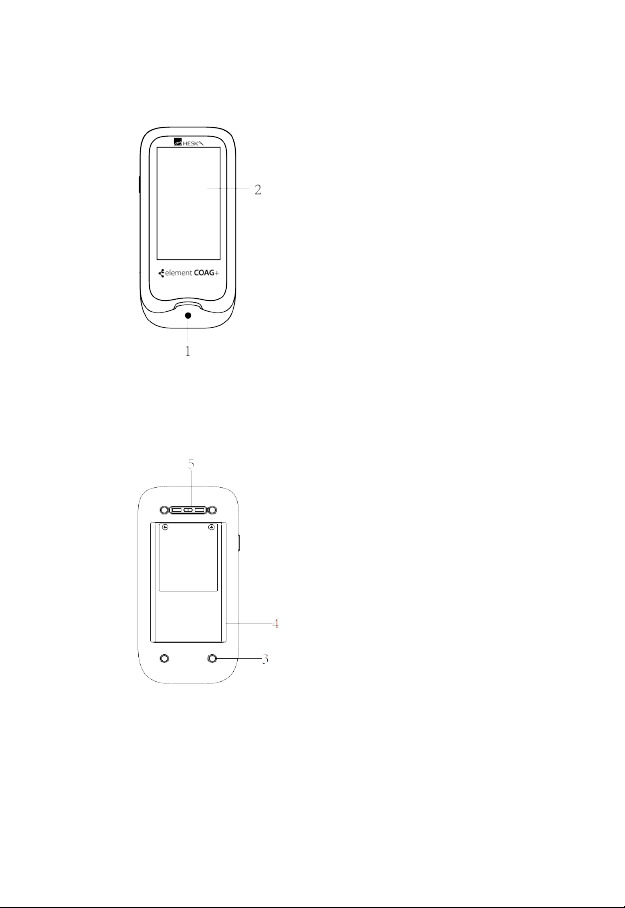
2. Product Overview
Front View
1. Test Strip Guide
2. Touchscreen
Back View
3. Footpad
4. Battery Cover with Label
5. Magnetic Charging Port
3
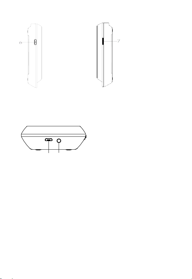
Left View
6. Power Button
Right View
7. Codechip Strip Slot
Top View
8. Micro USB Data Port
9. DC 5V Power Supply Jack
89

4
3. Operation Summary
4. Before Testing
Materials provided:
●Element COAG+ Analyzer
●Power supply
●USB disk (Manual)
Materials required (but not provided):
●Element COAG+ Analyzer test strip
●Puncture-resistant container for medical sharps
●Sterile alcohol
●Disposable gloves
Testing fresh venous blood samples:
●21-gauge needle or larger and syringe
●Sterile band aid
Testing citrated whole blood samples:
●Element COAG+ Re-Calcification Reagent
●100 μL pipette and pipette tips
●1.8 or 2.7 mL 3.2% (w/v) sodium citrate venous collection tube
Operation
Preparation
Meter Setup
Performing a
Test
Results
Query
Sample
Test
Insert
Test
Strip
Insert
Codechip of
Test Strip
Heating
Add
Sample Test
Language
Setting
Screen
Rotation
Reference
Range
Setting
Date/Time
Setting
Beeper
Setting
Backlight
Setting
Sleep
Setting
Sample No.
Switch
Setting
Upload
Setting
Codechip
Input Test
Strip
Information
QC Test
Input QC
Liquid
Information
Insert
Codechip of
QC Liquid
Heating
Add
Sample
Insert
Test
Strip
Test
Input Test
Strip
Information
Insert
Codechip of
Test Strip
Review Sample
Test Result
Delete
Result
Upload
Result
Query
Result
Review QC Test
Result
Transport
Mode Operator ID
Test
Type
PT Units
Setting
aPTT Units
Setting
WIFI

5
5. Precautions, Limitations and Warnings
The Element COAG+ Analyzer is for in vitro diagnostic use
only. Some environmental factors and incorrect operation
may cause the Element COAG+ Analyzer to not work
effectively or to report inaccurate results. Please read the
following warnings carefully before use and strictly follow
them.
As with all diagnostic tests, Element COAG+ Analyzer’s test
results should be analyzed and interpreted by combining the
condition, medical history, current and possible treatment of
a specific animal. Any results exhibiting inconsistency with
the clinical status should be repeated or supplemented with
additional test data or repeated with other testing methods.
5.1 Element COAG+™ Analyzer Care
●DO NOT spill any liquid on the Element COAG+ Analyzer. In this
case, immediately contact Heska’s Technical Support Services.
●The Element COAG+ Analyzer is a delicate instrument and
should be handled with care. Dropping or mishandling may cause
malfunction of Element COAG+ Analyzer.
●The Element COAG+ Analyzer should be transported in a carrying
case or a secure container.
●DO NOT store the Element COAG+ Analyzer below 14°F or above
104°F (-10ºC or above 40ºC).
●DO NOT use the Element COAG+ Analyzer with any other test
strips not provided by Heska.
5.2 Test Environment Requirements
●The temperature should be maintained between 50°F-95°F (10ºC
and 35ºC).
●This equipment has been tested and found to comply with
applicable EMC emission requirements as specified in EN 55032.
The emissions of the energy used are low and not likely to cause
interference in nearby electronic equipment.
●Do not use this instrument in a dry environment, especially if
synthetic materials are present. Synthetic clothes, carpets, etc.,
may cause static discharges in a dry environment. That may cause
incorrect operation or damage to the device. The recommended
humidity operating range is 10% to 90%.

6
●Do not use this instrument near cellular or cordless telephones,
walkie talkies, garage door openers, radio transmitters, or
other electrical or electronic equipment that are sources of
electromagnetic radiation, as these may interfere with the proper
operation of the instrument.
5.3 Patient Health Status
Current patient health status may cause inaccurate or unexpected test
results. It is important to take certain health factors into consideration
when interpreting the test results and deciding on a course of action for
your patients. Failure to do so may lead to an incorrect interpretation of
the test result.
5.4 Performing a Test
●The analyzer should be placed on a level surface that is free of
vibration. Testing on an uneven or unstable surface may cause
inaccurate results. DO NOT hold the analyzer in your hands during
the testing.
●Strictly follow the test procedure specified in the manual to perform
the test.
●DO NOT move or touch the analyzer during testing.
●After inserting the test strip, please confirm the codechip. Failure to
do so may cause inaccurate test result.
●Do not add the sample until the system prompts you to start adding
sample.
●When using fresh whole blood, the blood sample must be applied
to the test strip immediately after collection. Otherwise, the blood
sample may begin clotting and cause inaccurate results.
●The sample should be added in one continuous operation; do not
reapply additional sample.
●Do not use the device for unintended purposes, failure to do so
may cause unexpected test results.
5.5 Collecting Sample
●Use fresh venous whole blood and citrated whole blood. Do not
use plasma.
●The drop of blood must be a minimum of 10 μL.

7
5.6 Warning Information on Built-In Lithium Battery
●The Element COAG+ has a built-in lithium battery, which cannot be
removed by any user.
●The user must use the matching 5V special charger provided by
Heska to charge.
●Do not bring the analyzer close to a high-temperature heat source.
●Do not allow the analyzer to be hit or exert heavy pressure on the
analyzer.
●If it is found that there is leakage from the battery cover on the back
of the analyzer, direct skin contact should be avoided as much
as possible. In case of accidental contact with skin due to battery
leakage, please rinse with water. If your eyes come into contact
with battery liquid, you should also seek medical care.
●The battery should be disposed of with the analyzer in accordance
with local regulations.

8
6. Power ON/OFF
6.1 Battery and Charging
When turning on the analyzer for the rst time after unpacking, please
connect the adapter for power supply and turn off the transportation
mode. You do not need to repeat this operation for subsequent reboot.
Ensure the analyzer is fully charged (Approximately 3.5 hours to fully
charge) before using for the rst time.
When the screen displays E001, the adapter should be connected
immediately for charging. If the battery charge display shows only one bar,
it is recommended that the user connect the power adapter to charge as
soon as possible.
When the analyzer automatically shuts down due to insufcient power, the
user should charge the analyzer within 7 days. Otherwise the time and
date will require a reset.
The test results and all settings of the analyzer will be permanently stored
in the memory except the time and date.
6.2 Power ON
When the instrument is turned on for the rst time, the battery must be
fully charged. If the battery is low, do not turn the instrument on until the
power adapter provided with the instrument is inserted into the power jack
and connected to the external power supply. If the instrument is in power
off mode, short press the Power button and wait 2 seconds to power on.
If the instrument is in sleep mode, short press the Power button or insert a
test strip and wait 2 seconds to wake it up.
If Operator ID is set to On, the
analyzer automatically enters
Operator ID menu (Figure 1-1)
after it is turned on. Manually input
Operator ID and Password or obtain
by scanning (The default Operator
ID is "admin" and all must be
lower case. The default password
is "123456".) and touch “ ” to
enter main menu.
Please set Operator ID function
according to Section 7.7 of this
manual.
1-1

9
Once Operator ID is On, the Log out
icon in main screen will be enabled
and displayed in teal (Figure 1-2). To
switch between operators, please
return to the screen for inputting the
Operator ID by pressing the Log out
icon, and then re-enter the Operator
ID.
If Operator ID is Off, the Log Out
icon on main screen will be disabled
and displayed in teal with orange
frame (Figure 1-3), and the analyzer
will return to main screen after it is
turned on.
6.3 Sleep Mode
After a short press and release of the Power button, the screen will be
off and enter sleep mode. The sleep mode is a low power mode to save
battery power. Short press the Power button or insert a test strip and wait
2 seconds for device start-up.
If auto sleep function is enabled, the analyzer will automatically shut down
after the allotted idle time.
1-2
1-3
10
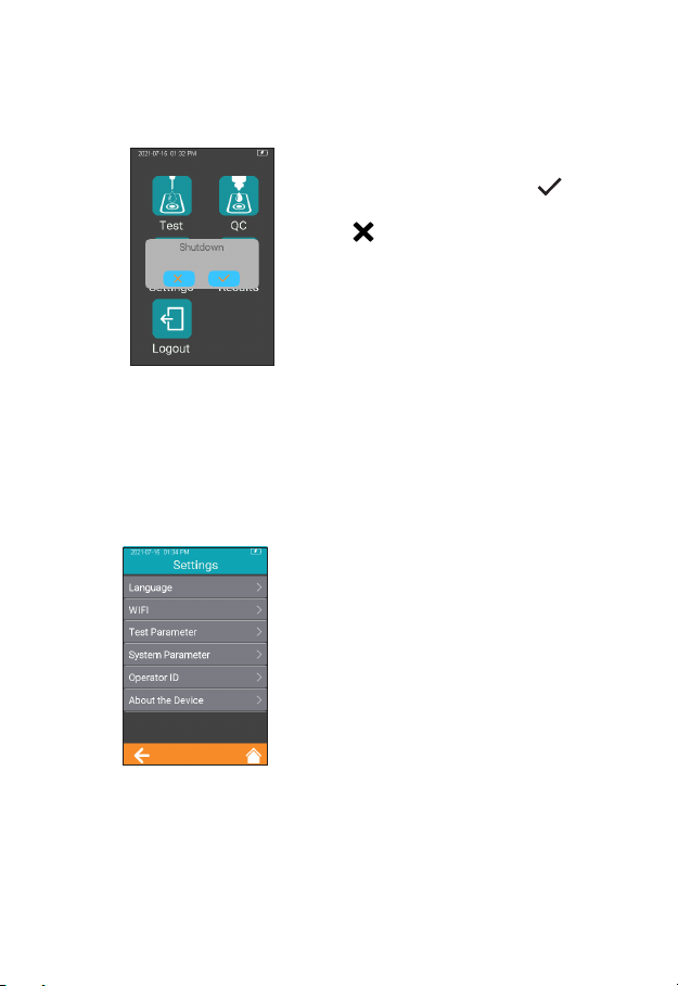
6.4 Power OFF
After depressing the Power button
for 3 seconds, the system will
deliver a message. Press " " to
power off the instrument, or press
" " to cancel the operation (Figure
1-4).
When the battery power of the
analyzer is exhausted, it will
automatically shut down.
7. Settings
7.1 Enter Settings Screen
Click "Settings" icon from the main
menu screen (Figure 1-2) to enter
the Settings screen (Figure 2-1).
1-4
2-1
11
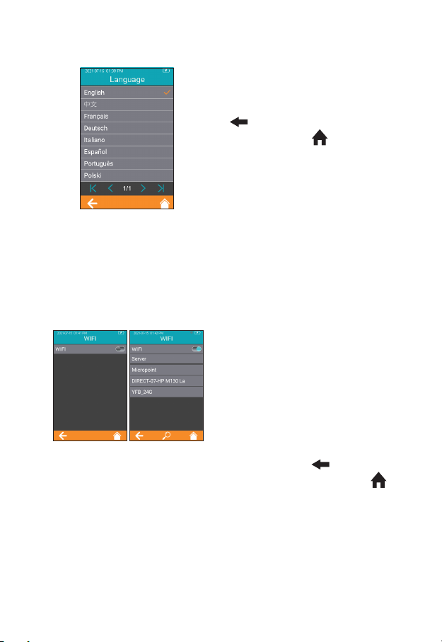
7.2 Language
Click "Language" from the Settings
screen (Figure 2-1) to view and
select a language (Figure 2-2). Click
" " to return to the previous
screen and click " " to return to
the main menu.
7.3 WIFI
WIFI connectivity allows the analyzer to connect with Practice Information
Management Software (PIMS) and can be used for data transmission.
Click “WIFI” from Settings menu
(Figure 2-1) to enter the WIFI menu
(Figure 2-3). When the WIFI button
is displayed in teal, it means WIFI is
turned on; when the WIFI button is
grayed out, it means WIFI is turned
off. Once WIFI is turned on and
connected successfully, the WIFI
icon on the upper right corner of the
menu is highlighted.
However, if WIFI is turned on but
fails to connect, the WIFI icon is
grayed out. Click “ ” to return to
the previous screen and click “ ”
to return to the main menu.
2-2
2-3
12
The system will search for nearby
hotspots and list automatically.
Click the hotspot name to enter the
password to connect successfully.
The system will remember the
password and connect to the last
connected hotspot automatically.
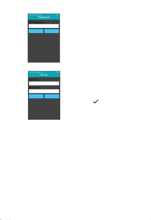
The server is used for wireless
data transmission with the specic
Practice Information Management
Software. Click “Server” to enter the
server IP address and port number,
and click “ ” to save. Set the
instrument’s IP address and port
number to be consistent with PIMS.
The loss of signal or access to bandwidth of one particular client may
vary depending on one or more of the following situations: the type
and number of other clients, the performance of the Access Point, the
presence of electromagnetic disturbances, and other potential interfering
factors, e.g., concrete walls.
2-4
2-5

13
7.4 Test Parameter
Click "Test Parameter" from the
Settings screen (Figure 2-1) to set
the parameters (Figure 2-6).
7.4.1 Sample No.
From the Test Parameter screen
(Figure 2-6), click Sample No. to set
the Sample number (Figure 2-7).
If the Sample No. button is grayed
out, then the sample does not need
to be numbered. If the Sample No.
button is teal, the sample can be
numbered manually or automatically.
Click " " to return to the previous
screen and click " " to return to
the main menu.
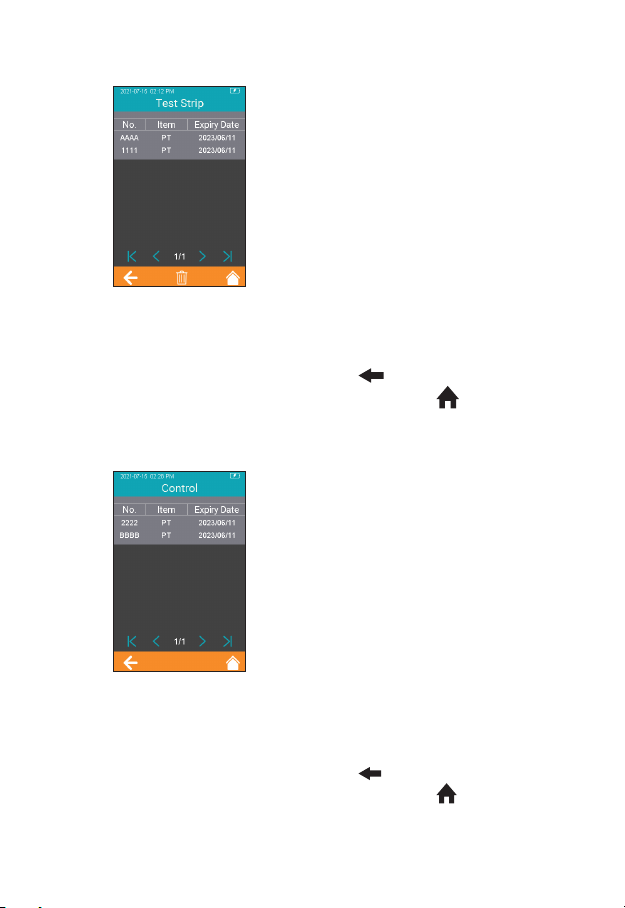
7.4.2 Codechip Strip
Click “Codechip” from Test
Parameter menu (Figure 2-6) to
enter Codechip menu (Figure 2-8).
Touch “ ” to search and view the
corresponding Codechip information
displayed based on the search
criteria. Click " " to return to the
previous screen and click " " to
return to the main menu.
2-6
2-7
2-8
14
Click “Test Strip” from Codechip
menu (Figure 2-8) to enter Test Strip
menu (Figure 2-9). The Codechip
information of the installed strip is
displayed in this menu. A new strip
Codechip can also be installed by
inserting the strip Codechip into the
Codechip slot (See the right gure in
Section 2 Product Overview). Please
make sure the side with the arrow
is facing up and the Codechip is
inserted completely. If the Codechip
has not been installed, the Codechip
should be manually entered into the
analyzer and displayed in the list.
Click " " to return to the previous
screen and click " " to return to
the main menu.
Click “Control” from Codechip
menu (Figure 2-8) to enter Control
menu (Figure 2-10). The Codechip
information of the installed control
is then displayed in this menu. A
new control Codechip can also be
installed by inserting the control
Codechip into the Codechip slot
(See the right gure on Section 2
Product Overview). Please make
sure the side with the arrow is facing
up and the Codechip is inserted
completely. If the Codechip has
not been installed, the Codechip
should be manually entered into the
analyzer and displayed in the list.
Click " " to return to the previous
screen and click " " to return to
the main menu.
2-9
2-10
15
In addition to the Codechip menu, a Codechip can be installed during the
test. When testing with a test strip or control, and an installed Codechip,
the installation operation is no longer required during the test; otherwise,
the system enters the prompt menu which enables the user to install the
desired Codechip accordingly.
The Codechip provides the analyzer with important information to perform
the coagulation test. The chip contains information about the test strip
code, the lot number, and the expiration date. The Codechip is required,
whenever a new test strip lot is used, so that the analyzer can read and
store the lot information about that particular lot of test strips.
●Do not forget to load the test strip Codechip that is supplied with
each pack of test strips before you perform the first test with these
strips. We recommend that you leave the Codechip in the analyzer
to protect the electrical contacts in the analyzer from becoming
dirty.
●Each Codechip belongs to a particular lot of test strips. Only
remove the Codechip when you are testing with test strips taken
from a new pack.
●Protect the Codechip from moisture and equipment that produces
magnetic fields.
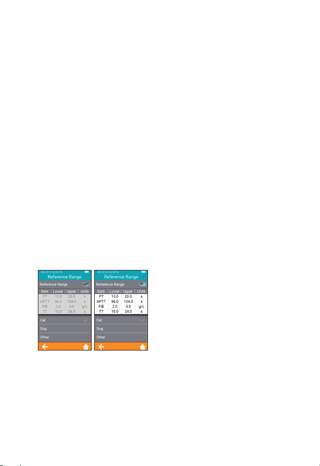
7.4.3 Reference Range
Click "Reference Range" from
Test Parameter screen (Figure
2-6) to enter the screen (Figure
2-11) that prompts the user to set
the reference range switch. Gray
button indicates the reference range
function is disabled and teal button
indicates the reference range is
enabled.
2-11

16
Click any value in the Reference
Range table to automatically enter
the menu which allows the user
to modify the value, and the user
can re-modify the upper and lower
limits (Figure 2-12) within the given
setting range. After the value range
is modied, if the test result is below
the lower limit, a popup will prompt,
"Illegal Input". Click " " to return
to the previous screen.
7.4.4 PT Units
Click “PT Units” from Test Parameter
menu (Figure 2-6) to enter the PT
Units menu (Figure 2-13). Default
format is PT. The display format
of the PT test result can be set
as required. The available display
formats are: PT/QC and PT. After
selecting a format, PT test result is
displayed accordingly. Click " "
to return to the previous screen
and click " " to return to the main
menu.
7.4.5 aPTT Units
Click “APTT Units” from Test
Parameter menu (Figure 2-6) to
enter the APTT Units menu (Figure
2-14). Default format is APTT. The
display format of the APTT test
result can be set as required. The
available display formats are: APTT
and APTT/QC. After selecting a
format, APTT test result is displayed
accordingly. Click " " to return to
the previous screen and click " "
to return to the main menu.
2-12
2-13
2-14
Table of contents


