hestan GESS08 User manual

©2019 Hestan Commercial Corporation
1
EN
OUTDOOR LIVING
SUITE
INSTALLATION INSTRUCTIONS
IMPORTANT - READ ALL INSTRUCTIONS BEFORE YOU BEGIN
THE INSTALLATION HEREIN SHOULD BE PERFORMED BY A QUALIFIED SERVICE TECHNICIAN
OR PROFESSIONAL OUTDOOR EQUIPMENT INSTALLER. MANY COMPONENTS ARE HEAVY AND
REQUIRE 2 OR 3 PERSONS TO UN-PACK AND SETUP THIS SUITE. FAILURE TO DO SO MAY RESULT
IN PERSONAL INJURY.
THE ELECTRICAL COMPONENTS SUPPLIED WITH THIS SUITE MUST BE INSTALLED BY A
LICENSED ELECTRICIAN AND CONNECTED IN ACCORDANCE WITH LOCAL CODES. THE SUITE
SHOULD BE CONNECTED TO A DEDICATED CIRCUIT BREAKER. ALL OUTLETS SUPPLIED WITH
THIS SUITE ARE GROUND FAULT CIRCUIT INTERRUPTER OUTLETS AND MUST BE PROPERLY
INSTALLED AND GROUNDED BY A LICENSED ELECTRICIAN TO GUARANTEE SAFE AND RELIABLE
OPERATION.
SOME PARTS INSIDE THE SUITE HAVE SHARP EDGES. CARE MUST BE TAKEN WHEN HANDLING
THE VARIOUS COMPONENTS TO AVOID PERSONAL INJURY. WEAR GLOVES WHEN HANDLING.
TOOLS REQUIRED:
Work gloves
Safety glasses
Power drill with masonry bits
Concrete / masonry anchors & hardware
Flat and Phillips screwdrivers
Socket wrench with 7/16” & 9/16” sockets and short extensions
Combination wrenches of 7/16” & 9/16” sizes
3/32 Allen wrench
Level
IF THE INFORMATION IN THE GAS-FIRED APPLIANCE MANUALS
ARE NOT FOLLOWED EXACTLY, A FIRE OR EXPLOSION MAY RESULT
CAUSING PROPERTY DAMAGE, PERSONAL INJURY, OR DEATH.
Flammable Gas - disconnect all propane or natural gas supplies to this unit
before servicing.
Electrical Parts & Components – disconnect all power supplies and
batteries before servicing.
AFTER INSTALLATION OF YOUR GRILL AND OTHER GAS-FIRED EQUIPMENT IN THIS
SUITE, READ THE MANUAL(S) PROVIDED WITH THOSE PRODUCTS CAREFULLY AND
COMPLETELY BEFORE USING THEM TO REDUCE THE RISK OF FIRE, BURN HAZARD,
OR OTHER INJURY. KEEP THIS MANUAL FOR FUTURE REFERENCE.
GESS08 GESS12 GESSP12 GESSK12
GESD08 GESD12 GESDP12 GESDK12
GESSB08 GESSB12 GESSBP12 GESSBK12
GESDB08 GESDB12 GESDBP12 GESDBK12

©2019 Hestan Commercial Corporation
2
EN
SUITE MODELS WITH STAINLESS STEEL TOP
Suite GESS08 shown with:
GABR36 Built-In Gas Grill
ABG122 Double Side Burner
AGAD36 Double Access Doors
GRSR24 Outdoor Fridge
ALL ITEMS PURCHASED SEPARATELY
Below are representations of some Hestan Outdoor Living Suites covered in this manual.
Suite GESDB12 shown with:
GABR42 Built-In Gas Grill
ABG122 Double Side Burner
AGTC Trash Chute
AGAD42 Double Access Doors
AGDR16 Double Drawers
AGTRC20 Trash & Recycling Center
GFDSR241 Outdoor Single Faucet Beer Dispenser
ALL ITEMS PURCHASED SEPARATELY
MODEL # DESCRIPTION
GESS08 GRILL, OUTDOOR LIVING SUITE, SS COUNTERTOP, 8 FOOT
GESD08 GRILL, OUTDOOR LIVING SUITE, SS COUNTERTOP w/ BEER DISPENSER, 8 FOOT
GESSB08 GRILL, OUTDOOR LIVING SUITE, SS COUNTERTOP & BAR, 8 FOOT
GESDB08 GRILL, OUTDOOR LIVING SUITE, SS COUNTERTOP w/ BEER DISPENSER & BAR, 8 FOOT
GESS12 GRILL, OUTDOOR LIVING SUITE, SS COUNTERTOP, 12 FOOT
GESD12 GRILL, OUTDOOR LIVING SUITE, SS COUNTERTOP w/ BEER DISPENSER, 12 FOOT
GESSB12 GRILL, OUTDOOR LIVING SUITE, SS COUNTERTOP & BAR, 12 FOOT
GESDB12 GRILL, OUTDOOR LIVING SUITE, SS COUNTERTOP w/ BEERDISPENSER & BAR, 12 FOOT
GESSP12 GRILL, OUTDOOR LIVING SUITE, SS COUNTERTOP, POWER BURNER, 12 FOOT
GESDP12 GRILL, OUTDOOR LIVING SUITE, SS COUNTERTOP w/ BEER DISPENSER, POWER BURNER, 12 FOOT
GESSBP12 GRILL, OUTDOOR LIVING SUITE, SS COUNTERTOP & BAR, POWER BURNER, 12 FOOT
GESDBP12 GRILL, OUTDOOR LIVING SUITE, SS COUNTERTOP w/ BEER DISPENSER & BAR, POWER BURNER, 12 FOOT
GESSK12 GRILL, OUTDOOR LIVING SUITE, SS COUNTERTOP, KAMADO GRILL, 12 FOOT
GESDK12 GRILL, OUTDOOR LIVING SUITE, SS COUNTERTOP w/ BEER DISPENSER, KAMADO GRILL, 12 FOOT
GESSBK12 GRILL, OUTDOOR LIVING SUITE, SS COUNTERTOP & BAR, KAMADO GRILL, 12 FOOT
GESDBK12 GRILL, OUTDOOR LIVING SUITE, SS COUNTERTOP w/ BEER DISPENSER & BAR, KAMADO GRILL, 12 FOOT
HESTAN OUTDOOR LIVING SUITES

©2019 Hestan Commercial Corporation
3
EN
LOCATING THE SUITE
LOCATION
When determining a suitable location for your grill and suite, take into account concerns such as exposure to
wind, rain, sprinklers, proximity to traffic paths, and keeping any gas supply line runs as short as possible.
Locate the grill only in a well-ventilated area. Never locate the grill in a building, garage, breezeway, shed or
other such enclosed areas without an approved ventilation system. Never locate the grill over, under, or next
to unprotected combustible construction.
AIRFLOW / WINDY AREAS
During heavy use, the grill will produce a lot of heat and smoke. The grill is designed to take in cool air at the
front control panel area, and send the combustion products and smoke out the exhaust gap at the rear of the
hood. IT IS IMPORTANT TO MAINTAIN THIS FLOW AT ALL TIMES.
Using the grill in windy areas can disrupt the proper flow and cause damage to your grill, or result in burn
hazards to the user. Initial indications of this situation are very hot control knobs. Using an oven mitt or
other protection, and while keeping your face away, immediately open the hood to release the built up
heat inside the grill. Turn down the burners to a lower setting. It is very important that the suite & grill is
oriented so the prevailing wind is toward the front of the grill as seen below in Fig. 1.
For built-in grill installations which consistently receive wind at the rear of the grill, a Wind Screen accessory
is available from Hestan. Contact your Hestan dealer for details.
Damage caused from use in windy conditions, such as melted knobs
and/or wiring, discoloration of the control panel, etc., is excluded from
warranty coverage.
The Hestan Outdoor Living suite features ventilation openings (louvers) on each end. These
openings must be clear to avoid accumulation of gas should there be a leak. These openings are
further described later in this manual.
Figure 1

©2019 Hestan Commercial Corporation
4
EN
2. The curb should be as level as possible and permanently anchored to the patio surface using
stainless steel masonry anchors & bolts (not included). If you choose not to permanently anchor your
suite, be sure you have moved it to its final location. Also be aware that the suites featuring a bar
are prone to tipping over unless the curb is anchored to the floor surface. The Outdoor Living Suite
is very heavy and difficult to move once assembly is complete and all equipment has been installed.
(8 foot Outdoor Living Suite curb shown)
CURB INSTALLATION
1. The Hestan Outdoor Living Suite must be located on a flat and level concrete or masonry patio
surface, not on direct soil. A licensed plumber and electrician should run their service lines to
the suite area prior to installation of the curb, in accordance with local codes. See dimensions
below for recommended location. See ELECTRICAL ITEMS section of this manual for details.
The gas line to the suite will require a shut-off that is easily accessible. Local codes may also
require a tracer wire be buried alongside the gas line for underground detection. See the GAS
CONNECTIONS section of this manual, and the appliance manual(s) for more details.

©2019 Hestan Commercial Corporation
5
EN
BACK AND SUPPORT WALL ASSEMBLY
3. Use 2 each 3/8-16 x 5/8” long hex bolts to align and attach the back wall to the curb. Be careful the
back wall does not tip over if the curb was not anchored down. Tighten all bolts.

©2019 Hestan Commercial Corporation
6
EN
BACK AND SUPPORT WALL ASSEMBLY
(continued)
1/4-20 x 1/2” BOLTS
& NUTS HERE
MAIN ELECTRICAL BOX
ROUTE THIS BOX
BETWEEN THIS SPACE.
ATTACH TO THIS WALL ON
2 STUDS AT REAR OF BOX.
ARROWS
POINTING UP
4. Attach support wall #1 to curb assembly and back wall as shown using 6 each 1/4-20 x 1/2” hex
bolts and hex nuts where needed. Do not fully tighten bolts yet. Route the main electrical box as
described below and attach using 2 each 1/4” hex nuts.
5. Install remaining support walls as you did in step 4. Each wall is numbered and has a corresponding
number on the curb and/or rear wall for ease of locating. (8 foot Outdoor Living Suite shown) Do
not fully tighten bolts yet. Note all arrows are pointing up.

©2019 Hestan Commercial Corporation
7
EN
INSTALL CORNER ASSEMBLY
6. Install corner assembly brackets as shown using 1/4-20 x 1/2” long hex bolts and hex nuts where
needed. For suites with Bar Top, install 4 brackets on each side.
7. Install 2 corner assemblies (4 assemblies for suites with Bar Top). Use 1/4-20 x 1/2” long hex bolts
and hex nuts where needed. Do not tighten until lift-off panels have been checked for proper t
(see Step 13).
1/4-20 x 1/2” BOLTS
& NUTS HERE

©2019 Hestan Commercial Corporation
8
EN
ELECTRICAL ITEMS
ELECTRICAL BOXES & CONDUIT
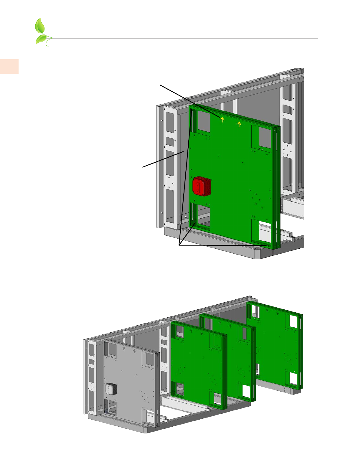
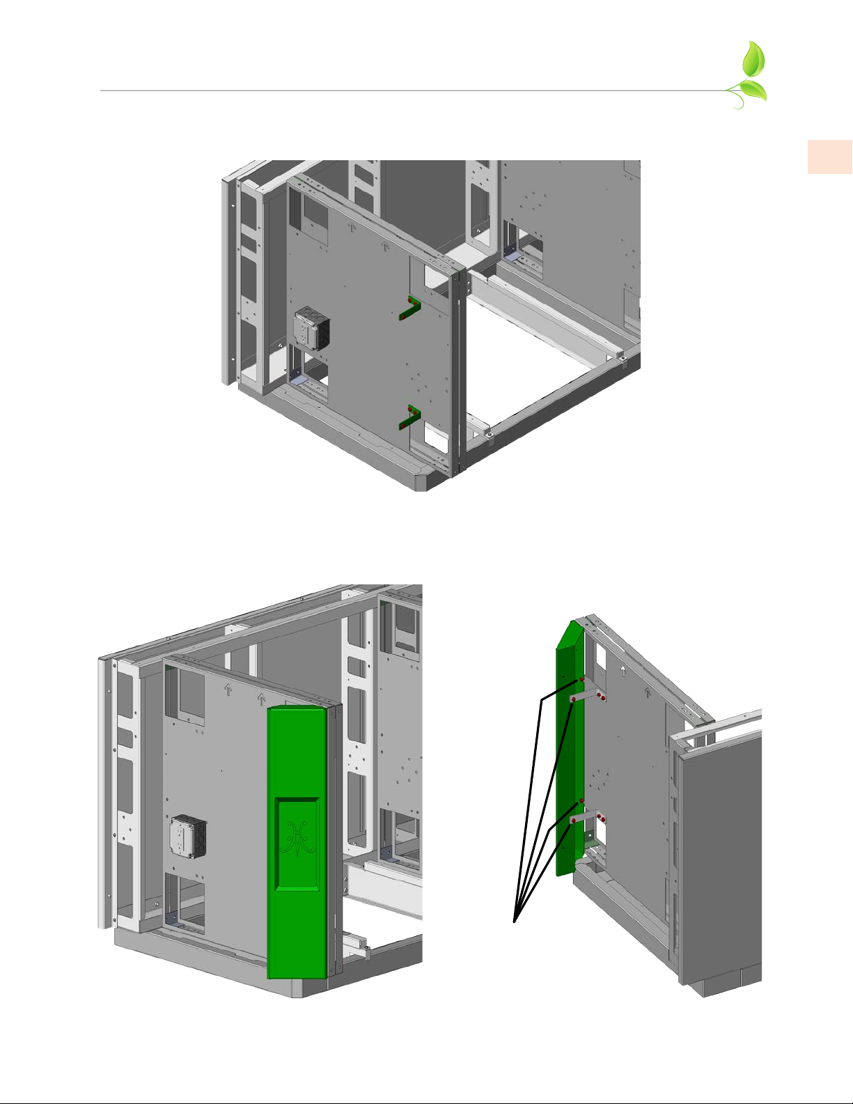
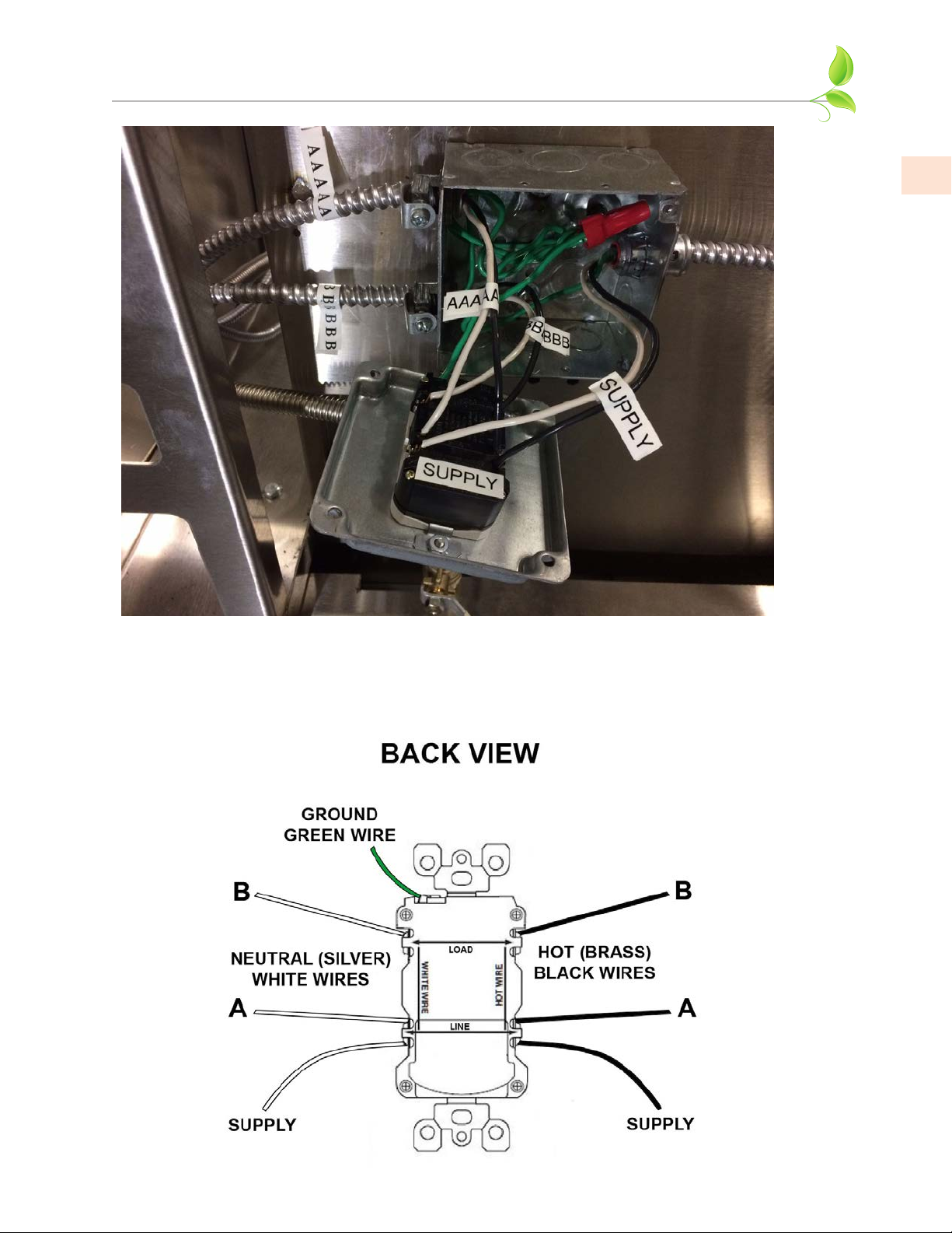
8. As mentioned in Step 1, a licensed electrician must run the electrical supply lines from the house
main electrical panel (20 amp breaker), to the recommended area below the curb base. This supply
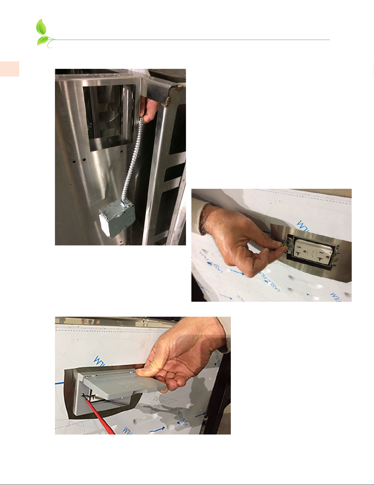
is brought into the main electrical box as shown in the photo on the next page. The flex conduits
coming out of this box are labeled “A” or “B”. The electrician will make up the final connections as
shown in the diagrams on the following pages.
This main electrical box contains a GFCI outlet, which protects all the “B” outlets. The “A” circuit
runs to the weather-proof GFCI outlet located on the right side of the Suite, or to the outlets at the
bar (for those models featuring a raised bar). Should the GFCI trip due to a fault at the Grill, Side
Burner, or Refrigerator (“B” outlets), it must be reset, and the other “A” outlets will not be affected.
Similarly, the “A” GFCI will not affect the “B” outlets if it trips due to a fault.
ELECTRICAL SUPPLY
The Hestan Outdoor Living Suite is completely pre-wired for ease of installation. The suite will
require a 20 amp supply (breaker) from the house main electrical panel. The licensed electrician
will have to run the appropriate wire size and conduit for this application. Rigid or flexible
conduit suitable for burial with water-tight connections are highly recommended from the house
main electrical panel, to the suite.
Important: The appliance(s) must be electrically grounded in accordance with local codes, or in
the absence of local codes with the National Electrical Code,
ANSI/NFPA 70-1990
.
Appliances (grill, side burner, refrigerators, etc. ) are equipped with a flexible electrical supply
cord featuring a three-prong grounding plug. It is imperative that this plug be connected to a
properly grounded three-prong receptacle. If the receptacle is not the proper grounding type,
contact an electrician. Do not remove the grounding prong from this plug.
The appliances are designed for 120 volt AC power and must be plugged into a Ground Fault
Circuit Interrupter (GFCI) protected circuit. For gas-burning appliances, do not connect to
the electrical supply until after gas connections have been made and leak checks have been
performed.
KEEP ANY ELECTRICAL CORDS AND FUEL SUPPLY HOSES AWAY FROM ANY HEATED
SURFACES.
• To protect against electric shock, do not immerse cord or plugs in water or other liquid.
• Unplug from the outlet when not in use and before cleaning. Allow to cool before putting
on or taking off parts.
• Do not operate any outdoor cooking gas appliance with a damaged cord or plug, or after the
appliance malfunctions or has been damaged in any manner. Contact the manufacturer for
repair.
• Do not let the cord hang over the edge of a table or touch hot surfaces.
• Do not use an outdoor cooking gas appliance for purposes other than intended.
• Use only a Ground Fault Circuit Interrupter (GFCI) protected circuit with this outdoor
cooking gas appliance.
• Never remove the grounding prong or use with a 2-prong ground adapter.
• Use only extension cords with a 3-prong grounding plug, rated for the power of the
equipment, and approved for outdoor use with a W-A marking.

©2019 Hestan Commercial Corporation
9
EN
MAIN ELECTRICAL BOX SHOWING SUPPLY
LINE ENTERING ON RIGHT SIDE OF BOX.
ELECTRICAL ITEMS
(continued)

©2019 Hestan Commercial Corporation
10
EN
ELECTRICAL ITEMS
(continued)
MAIN ELECTRICAL BOX
WITH GFCI OUTLET
GFCI
OUTLET
OUTLET OUTLET
SERVICE
LINE IN 8 FOOT SUITE WITHOUT BAR
GESS08, GESD08, GES08
A
AA
A
BB
B
MAIN ELECTRICAL BOX
WITH GFCI OUTLET
SERVICE
LINE IN
A
B
GFCI
OUTLET
OUTLET OUTLET
A
A
B
B
8 FOOT SUITE WITH BAR
GESSB08, GESDB08, GESB08
A
MAIN ELECTRICAL BOX COMPLETE

©2019 Hestan Commercial Corporation
11
EN
ELECTRICAL ITEMS
(continued)
MAIN ELECTRICAL BOX
WITH GFCI OUTLET
GFCI
OUTLET
OUTLET OUTLET
SERVICE
LINE IN
12 FOOT SUITE WITHOUT BAR
GESS12, GESD12, GES12
A
A
BB B
A
A
MAIN ELECTRICAL BOX
WITH GFCI OUTLET
GFCI
OUTLET
OUTLET OUTLET
OUTLET
SERVICE
LINE IN
12 FOOT SUITE WITH BAR
GESSB12, GESDB12, GESB12
A
B
A
A
A
BB
A
RIGHT SIDE OF SUITE
(For Suite without Bar)
GFCI OUTLET WITH
WEATHERPROOF COVER

©2019 Hestan Commercial Corporation
12
EN
INSTALL OUTER PANELS
9. The GFCI outlet on the right side of the suite is shipped loosely and must be passed through the
space shown below and installed from behind the right panel (does not apply to Suite with a bar).
Line up and install 4 each #10
screws as shown here.
Install the foam gasket, and
weather-proof cover with the
screws provided.

©2019 Hestan Commercial Corporation
13
EN
INSTALL OUTER PANELS
(continued)
10. Install small front panel as shown using 2 each 1/4-20 x 1/2” long hex bolts and hex nuts. With
wiring complete, secure right panel as shown with a #10 self-drilling screw.
1/4-20 x 1/2” BOLTS
& NUTS HERE
#10 SELF-
DRILLING SCREW
11. Install large front panel as shown using 1/4-20 x 1/2” long hex bolts and hex nuts where needed.
(8 foot Outdoor Living Suite shown)
1/4-20 x 1/2” BOLTS & NUTS
LOCATED UNDERNEATH

©2019 Hestan Commercial Corporation
14
EN
MOUNT GRILL ELECTRICAL BOX & LEFT PANEL
12. Mount the electrical box that came with your Hestan grill as shown and secure with #10 self-drilling
screws provided. Use the provided Wire Harness Extension (p/n 009938) to connect the box to
the grill wire harness. Arrange the wires in such a way to prevent damage during installation of the
grill, and from heat. At this point, it is also recommended the plumber run the gas connections for
the Grill and Side Burner (see pg. 17). As mentioned before, a gas shut-off valve must be located in
a readily accessible location for shut-off when the appliances are not in use, or for servicing. See
reference photos at the end of this manual.
13. Mount the lift-off panel on the left side of the suite. There are pins on either side for locating. The
louvers located on these side panels are needed for ventilation and must not be blocked. If this lift-
off panel does not install/remove easily, you may need to adjust the corner assembly to accommodate
(see Step 7).

©2019 Hestan Commercial Corporation
15
EN
INSTALL TOP
14. Before installing the top, you should now go back and tighten all bolts everywhere else in the suite.
Install the top. Get assistance from another person to help lift the top and position correctly. Install
1/4-20 x 1/2” long hex bolts and flat washers where needed. (8 foot Outdoor Living Suite shown)
1/4” BOLTS &
WASHERS HERE
ASSEMBLY OF THE SUITE IS NOW COMPLETE. YOU MAY NOW INSTALL THE APPLIANCES,
CABINETS, AND OTHER PRODUCTS AS PER THE INSTRUCTION MANUALS SUPPLIED WITH
THOSE PRODUCTS.

©2019 Hestan Commercial Corporation
16
EN
BAR TOP INSTALLATION (FOR MODELS WITH BAR)
HESTAN OUTDOOR LIVING SUITES WHICH FEATURE A BAR TOP (GESSBxx, GESDBxx, GESBxx)
FOLLOW THE SAME STEPS AS DESCRIBED EARLIER IN THIS MANUAL. STEPS UNIQUE TO THESE
MODELS ARE DETAILED BELOW.
1/4-20 x 1/2” BOLTS
& NUTS HERE
BACK AND SUPPORT WALL ASSEMBLY
1. Attach support wall #1 to curb assembly and back wall as shown using 6 each 1/4-20 x 1/2” hex bolts
and hex nuts where needed.
2. Install remaining support walls as you did in step 1. Each wall is numbered and has a corresponding
number on the curb and/or rear wall for ease of locating. (12 foot Outdoor Living Suite with Bar
shown).

©2019 Hestan Commercial Corporation
17
EN
BAR TOP INSTALLATION
(continued)
3. Install the bar top. Get assistance from another person to help lift the top and position correctly.
4. While an assistant is holding the bar top in place, reach underneath and secure the top with 1/2” nuts
and lock-washers provided. Then secure the large back panels with 1/4-20 x 1/2” long bolts and flat
washers.

©2019 Hestan Commercial Corporation
18
EN
INSTALL COUNTERTOP
NOTE: IF YOU HAVE A SUITE FOR POWER BURNER OR KAMADO GRILL, SEE THE
APPENDIX AT THE BACK OF THIS MANUAL FOR DETAILS BEFORE INSTALLING
THE COUNTERTOP.
5. Install the countertop. Get assistance from another person to help lift the top and position
correctly. Install 1/4-20 x 1/2” long hex bolts and flat washers where needed. When
complete, apply a bead of clear silicone sealant along the joint indicated.
APPLY SEALANT
ALONG THIS JOINT
HOLE FOR
OPTIONAL BEER
DISPENSER
FOOTRAIL INSTALLATION (FOR MODELS WITH BAR)
MOUNTING
SCREWS
SETSCREW
1. Install the footrail brackets on the rear wall
as shown using #10-24 x 1/2” long flat-head
mounting screws. Do not fully tighten the screws
yet. It might be easier to align the screws with a
helper on the other side of the wall.
Check to see if the setscrew in each bracket is
backed out enough to allow the tube to pass
through easily.
NOTE: For installation of the footrail, it is assumed the curb base of the entire suite was
installed on a flat and level concrete or masonry patio surface (see page 4). If the surface
is not level, the bottom pads of each bracket may
not rest fully on this surface. Also if you decide
to tile around the suite after installation, the
bottom pads of the footrail will still be on the same
level as the underside of the curb base. Your tile
installation will need to make allowances for this
condition.

©2019 Hestan Commercial Corporation
19
EN
GAS CONNECTIONS AND FINAL ASSEMBLY
ASSEMBLY OF THE SUITE IS NOW COMPLETE. YOU MAY NOW INSTALL THE
APPLIANCES, CABINETS, AND OTHER PRODUCTS AS PER THE INSTRUCTION MANUALS
SUPPLIED WITH THOSE PRODUCTS.
GAS SUPPLY
Gas connections should be made by a qualified plumber, or your professional outdoor appliance installer.
All fixed (non-mobile) appliances must be fitted with an accessible upstream gas shutoff valve as a means
of isolating the appliance for emergency shut off and for servicing. See reference photo at the end of
this manual.
Make certain new piping and connections have been made in a clean manner and have been purged so
that piping compound, chips, etc. will not clog regulators, valves, orifices, or burners. Use pipe joint
compound / thread sealant approved for natural and LP gases.
NEVER CONNECT THE GRILL OR SIDE BURNER TO AN UNREGULATED GAS SUPPLY. Before
proceeding, ensure the appliance is fitted for Natural or Liquid Propane gas. Connecting to an improper
gas type will result in poor performance and increased risk of damage or injury. Gas type and gas
consumption (BTU per hour) for each burner type is shown on the rating label affixed to each appliance.
Installation of this cooking appliance must be made in accordance with local codes. In the absence of
local codes, this unit should be installed in accordance with the National Fuel Gas Code No.
Z223.1/
NFPA 54
, Natural Gas and Propane Installation code
CSA B149-1
, or Propane Storage and Handling Code
B149.2.
NOTE: See rating label for manifold pressure for the type of gas of your appliance.
NOTE: If your Suite is to be connected to a Whole-House LP Piped System, please read the GAS
CONNECTIONS section of your Hestan Grill manual for information on this unique installation, and to
contact Hestan Customer Service to order an LP Piped System Kit.
FOOTRAIL INSTALLATION
(continued)
2. Pass the textured tube through
all footrail brackets. Check
that an equal length of tubing is
exposed beyond the left-most
and right-most brackets. When
you are OK with the position,
lock the tube in place with all
setscrews. Tighten all mounting
bracket screws as well.
3. Attach endcaps to both ends
of the tube and secure with
setscrews on the bottom.
SETSCREW

©2019 Hestan Commercial Corporation
20
EN
GAS CONNECTIONS AND FINAL ASSEMBLY
(continued)
1. The Outdoor Living Suite is shipped with an interplumb kit to simplify connecting side burner and
grill together as shown below. HOWEVER, EACH APPLIANCE MUST BE CONNECTED TO ITS
OWN REGULATOR. DO NOT USE ONE REGULATOR FOR BOTH APPLIANCES.
2. The remaining gas connections shown above must be completed by the qualified plumber or
professional outdoor appliance installer. See reference photo on the next page for typical flex hose
and shut-off valve location. Flex hose, shut-off valve, and misc. fittings must be provided by the
homeowner and installed by the qualified plumber or professional outdoor appliance installer. The
gas regulator is supplied with the grill & side burner (or power burner).
The above image is a suggestion only. Depending on which cabinetry was selected to go beneath
the grill, it may be necessary for the plumber to route the regulator, fittings, and hoses in a different
configuration to allow for the installation of the cabinet.
At all times, the shut-off valve must be located near the left side of the suite, near the floor, so it is
easily accessible for service or emergency shut-off (see reference photos on next page).
A FULL LEAK TEST MUST BE PERFORMED ON ALL GAS CONNECTIONS & HOSES BEFORE
USING THE APPLIANCES. Refer to the appliance manuals for instructions on this very important
step.
INTERPLUMB KIT
(SUPPLIED WITH SUITE)
FLEX HOSE
& FITTINGS
(SUPPLIED BY CUSTOMER)
SHUT-OFF
VALVE
(SUPPLIED BY CUSTOMER)
INCOMING
GAS SERVICE
SUITE WITH GRILL AND SIDE BURNER
(POWER BURNER IS SIMILAR)
REGULATOR
(SUPPLIED WITH GRILL) REGULATOR
(SUPPLIED WITH
SIDE BURNER)
This manual suits for next models
15
Table of contents
Other hestan Grill manuals

hestan
hestan Aspire EABR36LPBK User manual

hestan
hestan GABR User manual

hestan
hestan GESC12 User manual

hestan
hestan GABR Series User manual

hestan
hestan GES08 User manual

hestan
hestan DELUXE GRILL AGCP36 Series User manual

hestan
hestan GABRCX2 Series User manual

hestan
hestan Aspire EABR30-NG User manual

hestan
hestan Deluxe GABR CX2 Series User manual

hestan
hestan GESSC12 User manual