HETRONIC TG DIG-V1 User manual

YOUR #1 PARTNER IN RADIO REMOTE CONTROLS
Operator Manual
Hetronic USA
4300 Highline Blvd., Bldg. A
Oklahoma City, OK 73108
405-946-3574 Fax 405-946-3564
OPMN_TG_0001.0
6/04
www.hetronic.com
Hetronic Canada
45 Sinclair Avenue
Halton Hills, Ontario L7G 4X4
+1-800-816-4459 Fax +1-905-702-0501
© 2004 Hetronic, Inc.
All rights reserved. No part of this publication may be reproduced, transmitted, transcribed, stored in a retrieval
system, or translated into any language in any form by any means without the written permission of Hetronic.
TG Systems
TG DIG-V1

2
Introduction . . . . . . . . . . . . . . . . . . . . . . . . . . . . . 3
The Manual . . . . . . . . . . . . . . . . . . . . . . . . . . . 3
Production and System Numbers . . . . . . . . . . 3
Unauthorized Replacement Parts . . . . . . . . . . 3
Before Attempting to Operate This System . . . 3
Hetronic System Components. . . . . . . . . . . . . 4
Receiver Standard Features . . . . . . . . . . . 4
Transmitter Standard Features . . . . . . . . . 4
System Overview. . . . . . . . . . . . . . . . . . . . . . . 4
Theory of Operation . . . . . . . . . . . . . . . . . 4
E-Stop Function . . . . . . . . . . . . . . . . . . . . 4
Transmitter Sleep Mode . . . . . . . . . . . . . . 4
Receiver Safe Mode . . . . . . . . . . . . . . . . . 4
Safety . . . . . . . . . . . . . . . . . . . . . . . . . . . . . . . . . . 5
Safety Alerts . . . . . . . . . . . . . . . . . . . . . . . . . . 5
Notations . . . . . . . . . . . . . . . . . . . . . . . . . . . . . 5
Practices and Laws . . . . . . . . . . . . . . . . . . . . . 5
Required Operator Training. . . . . . . . . . . . . . . 5
Possible Sources of Danger . . . . . . . . . . . . . . 5
Operation and Work Area Safety. . . . . . . . . . . 5
Protective Features . . . . . . . . . . . . . . . . . . . . . 5
To Stop In An Emergency . . . . . . . . . . . . . . . . 5
Maintenance and Storage . . . . . . . . . . . . . . . . 5
Receiver Installation . . . . . . . . . . . . . . . . . . . . . . 6
RX 14-0004 Receiver Components. . . . . . . . . 6
RX 20 Receiver Components . . . . . . . . . . . . . 7
Receiver Location . . . . . . . . . . . . . . . . . . . . . . 7
Mounting the Receiver. . . . . . . . . . . . . . . . . . . 7
RX 14-0004 Mounting Dimensions . . . . . . 8
RX 20 Mounting Dimensions . . . . . . . . . . 8
Standard External Antenna Installation . . . 9
GainFlex Antenna Installation . . . . . . . . . . 9
Connect Electrical Wiring . . . . . . . . . . . . . . . 10
TG Dig-V1 with RX 14-0004 Outputs . . . 10
TG Dig-V1 with RX 20 Outputs . . . . . . . . 11
Overhead Traveling Crane (Mat. Handl.) 12
TG Transmitter . . . . . . . . . . . . . . . . . . . . . . . . . . 13
Frequency and Address Settings . . . . . . . . . 13
TG DIG-V1 Transmitter . . . . . . . . . . . . . . . . . 13
Transmitter Setup. . . . . . . . . . . . . . . . . . . . . . . . 14
Test Procedures . . . . . . . . . . . . . . . . . . . . . . . . . 14
Test the System . . . . . . . . . . . . . . . . . . . . . . . 14
LED Designations & Layout . . . . . . . . . . 15
Operation . . . . . . . . . . . . . . . . . . . . . . . . . . . . . . 16
Holding the Transmitter . . . . . . . . . . . . . . . . . 16
Visual Check . . . . . . . . . . . . . . . . . . . . . . . . . 16
Start-Up Procedure . . . . . . . . . . . . . . . . . . . . 16
To Stop In An Emergency . . . . . . . . . . . . . . . 17
Safe Mode . . . . . . . . . . . . . . . . . . . . . . . . . . . 17
Maintenance . . . . . . . . . . . . . . . . . . . . . . . . . . . . 17
Changing the Battery. . . . . . . . . . . . . . . . . . . 17
Battery Disposal . . . . . . . . . . . . . . . . . . . . . . 17
Battery Charging System. . . . . . . . . . . . . . . . 17
Features . . . . . . . . . . . . . . . . . . . . . . . . . 17
The Battery Charger . . . . . . . . . . . . . . . . 17
Charging the Battery . . . . . . . . . . . . . . . . 18
Hetronic Battery Information . . . . . . . . . . 18
RF Modules. . . . . . . . . . . . . . . . . . . . . . . . . . . . . 19
Description of Functions . . . . . . . . . . . . . . . . 19
Setting the Frequency Channel . . . . . . . . . . . 19
CS 458 RF-Synthesizer . . . . . . . . . . . . . . . . . 20
CS 447 RF-Synthesizer . . . . . . . . . . . . . . . . . 21
CS 434 RF-Synthesizer . . . . . . . . . . . . . . . . . 22
STD-402 RF-Synthesizer . . . . . . . . . . . . . . . 23
CS 429 RF-Synthesizer . . . . . . . . . . . . . . . . . 24
Troubleshooting . . . . . . . . . . . . . . . . . . . . . . . . . 25
Specifications. . . . . . . . . . . . . . . . . . . . . . . . . . . 28
Installation / Safety Data Sheet. . . . . . . . . . . . . 29
Definitions & AWG Metric Conversions . . . . . . 30
Abbreviations . . . . . . . . . . . . . . . . . . . . . . . . . . . 31
Warranty . . . . . . . . . . . . . . . . . . . . . . . . . . . . . . . 32
TABLE OF CONTENTS

3
INTRODUCTION
Thank you for purchasing the Hetronic radio remote
control system. Hetronic radio remote controls are the
highest caliber in remote control value, performance
and safety.
Hetronic radio remote controls use the latest frequency
synthesizer technology to eliminate the problems
typically associated with radio remote control systems.
THE MANUAL
Before operation of the crane/machine and remote
control system, read your manuals carefully and
completely. The contents of this manual will provide
you with an understanding of safety instructions and
controls during normal operation and maintenance.
PRODUCTION AND SYSTEM NUMBERS
When contacting your dealer or Hetronic about service,
repair or replacement parts, know the Production and
System numbers of the transmitter and receiver.
The numbers are located on the label that is affixed to
the unit itself.
Record the Production and System numbers here:
UNAUTHORIZED REPLACEMENT PARTS
Use only Hetronic replacement parts. The replacement
of any part with anything other than a Hetronic
authorized replacement part may adversely affect the
performance, durability, and safety of this system and
may void the warranty. Hetronic disclaims liability for
any claims or damages, whether warranty, property
damage, personal injury or death arising out of the use
of unauthorized replacement parts.
BEFORE ATTEMPTING TO OPERATE THIS
SYSTEM:
1. Make sure all installation has been properly
completed.
2. ALWAYS be sure the crane/machine and radio
remote control Emergency-Stop functions work
properly before beginning any crane/machine
operation.
3. Understand all Safety Precautions provided in the
manuals.
4. Review control functions and operation of the
machine and this radio remote control system.
5. Surge suppressors (RC type only) must be used
when the receiver is controlling magnetic
contactors.
6. When not in use, turn the transmitter off and store
in a safe place to prevent unauthorized use.
7. If the crane/machine does not respond properly,
stop operation immediately. Turn off the
transmitter and report the condition to the
appropriate technician or supervisor.
8. Turn off the transmitter and remove the battery
before any maintenance work is done.
IMPORTANT: AVOID SYSTEM DAMAGE - ALWAYS
disconnect receiver power supply and control wiring
before welding on any part of the crane/machine.
9. Turn off the transmitter key switch when changing
the battery or taking a break.
10. Always have fresh batteries on hand or an
optional rechargeable battery pack in the battery
charger to ensure the availability of a fully
charged battery.
11. Installation, setup and service must be performed
by authorized personnel only.
12. Use only Hetronic spare parts.
1
23
5
4
1. Specific approvals such as BTZ, FCC, CE, etc.
2. The type of transmitter or receiver.
3. Frequency and RF unit.
4. Production Number - The first digit indicates the
manufacturing facility (1=H-Germany, 2=H-Malta,
3=H-US, 4=H-Italy). The next four digits are the
production month and year. The last 6 digits are
the system address.
5. System Number - The Hetronic Part Number of
the transmitter or receiver.
Transmitter Production Number
Receiver Production Number
System Number
INTRODUCTION

4
HETRONIC SYSTEM COMPONENTS
The Hetronic radio remote control system consists of a
receiver and transmitter with belt, battery charger, and
two rechargeable batteries.
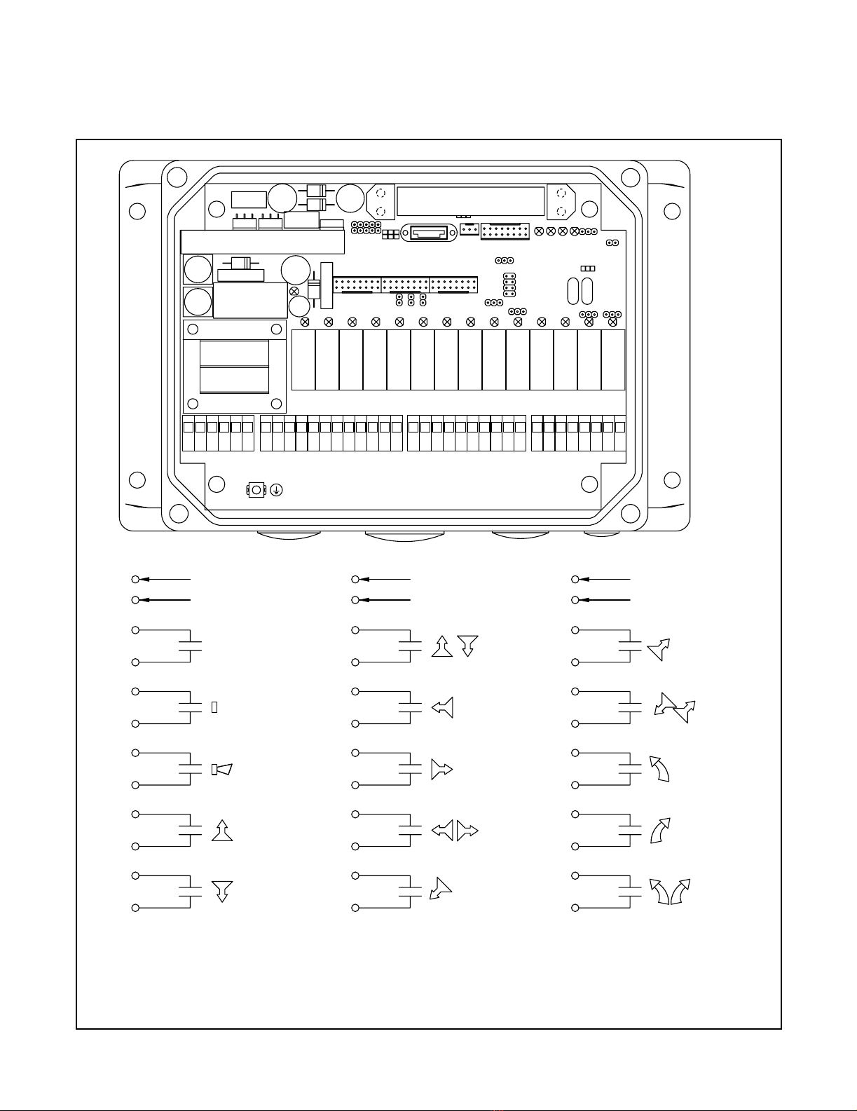
RX 14-0004 Receiver Standard Features
Start relay, horn relay, E-Stop relay
• Up to 14 digital outputs
• Self-diagnostics
• 48 V, 115 V or 230 V for AC cranes/machines
• 12VDC or 24VDC for DC cranes/machines
RX 20 Receiver Standard Features
Start relay, horn relay, E-Stop relay, and two option
relays
• Up to 20 digital outputs
• Self-diagnostics
• 48 V, 115 V or 230 V for AC cranes/machines
• 12VDC or 24VDC for DC cranes/machines
TG Dig-V1 Transmitter Standard Features
• Removable key power switch
• E-stop switch
• 1 2-detent start pushbutton
• 1 2-detent horn pushbutton
• 8 2-speed motion pushbuttons
• 2 2-detent latching/momentary option pushbuttons
•Sleepmode
• 100 m (300 ft.) range
• Internal antenna
• Shoulder strap
SYSTEM OVERVIEW
Theory of Operation
The Hetronic radio remote control system includes a
transmitter and a receiver. These systems operate over
the 400-470 MHz radio band range (70 cm band) and
are FCC approved.
The transmitter generates the electronic signal that
communicates with the receiver. The transmitter and
receiver are set with identical address codes and
frequency channels. This allows operation of multiple
systems within the same area without signal
interference.
The receiver only accepts commands from the
transmitter with the same address code.
NOTE: The receiver and transmitter have the address
code set at the factory.
E-Stop Function
The most important feature of the radio remote control
system is the E-Stop. The transmitter sends the E-stop
status signal along with the specified crane/machine
function. This method confirms that ongoing operations
are safe. If the E-stop pushbutton is pressed, the E-stop
relay in the receiver causes all crane/machine motions
to stop. The receiver goes into Safe mode.
To restart the system, disengage the E-stop button and
press the Start button.
The E-Stop responds faster than any other function.
When E-Stop is engaged, the system ignores any other
signal that is transmitted. The problem must be
corrected before the system will respond to any other
signal.
The E-Stop is self-monitoring and redundant in the
transmitter and receiver. The system performs a
self-test to ensure the E-Stop circuit is working properly.
If an error is detected, the system automatically goes
into Safe mode.
When the transmitter is turned on, it performs a self-test
to be sure that communications are within designated
parameters. If an error is detected, the transmitter will
not transmit any signals.
Transmitter Sleep Mode
The transmitter sleep mode is designed to prevent
accidental operation. The transmitter can be set for the
following sleep modes:
• 30 seconds
• 2 minutes
• 5 minutes
If the transmitter is not used for the set sleep mode
period, it turns itself off. The controls are not operational
while the transmitter is in sleep mode. To restart the
transmitter, turn the key switch off and then back on, and
press the Start button.
IMPORTANT: If the transmitter has a latching
pushbutton that is engaged, sleep mode will not occur.
Receiver Safe Mode
The following conditions cause the receiver to go into
Safe mode:
• The transmitter goes into Sleep Mode
• Radio signal interference
• Transmitter out of operating range
• E-Stop button is activated
• E-Stop circuit failure
• Low battery sends E-stop after time out
When the transmitter signal is no longer sensed by the
receiver, the Time Out process begins. The Time Out
period is set to 450 msec at the factory. If the receiver
does not establish contact with the transmitter within
that time period, it goes into the Safe Mode.
In Safe Mode, the receiver shuts off activation power to
the output relays and activates the E-stop function.To
restart the system, be sure the transmitter signal is
active and sensed by the receiver. Then press the Start
pushbutton.

5
SAFETY ALERT
Look for this symbol to point out
important safety precautions. They
mean:
Attention!
Personal Safety Is Involved!
Become Alert!
Obey The Message!
The safety alert symbol is used in decals on the unit
and with proper operation procedures in this manual.
Understand the safety message. It contains important
information about personal safety on or near the unit.
NOTATIONS
NOTE: General reference information for proper
operation and maintenance practices.
IMPORTANT: Specific procedures or information
required to prevent damage to unit or equipment.
PRACTICES AND LAWS
Practice usual and customary safe working
precautions, for the benefit of yourself and others.
Understand and follow all safety messages. Be alert to
unsafe conditions and the possibility of minor,
moderate, or serious injury or death. Learn applicable
rules and laws in your area.
REQUIRED OPERATOR TRAINING
Original purchaser of this unit was instructed by the
seller on safe and proper operation. If unit is to be used
by someone other than original purchaser; loaned,
rented or sold, ALWAYS provide this manual and any
needed safety training before operation.
ALWAYS review the operators manual of any machine
to be controlled by radio remote control.
POSSIBLE SOURCES OF DANGER
This system makes remote control via radio signals
possible. However, the transmission of control
commands can take place around obstacles and out of
the operator’s direct sight. To prevent accidental
start-up and possible injury or damage:
1. Always engage the E-stop button and switch
"OFF" the transmitter when it is not in use.
Remove the key if the unit is placed any distance
away from the operator.
2. Disconnect the power supply before any
assembly, maintenance or repair work is done.
3. Never remove or alter any of the safety features
of this system.
OPERATION AND WORK AREA SAFETY
The work area must be free from obstacles, debris or
other tripping hazards. Avoid uneven work areas and
any rough terrain. Always be sure of your footing.
Be aware of overhead obstacles that may interfere with
machine operation.
PROTECTIVE FEATURES
This radio remote control system is equipped with
electronic and mechanical safety features. Processing
of control signals transmitted from other transmitters is
not possible, since transmission coding is unique to
each system.
These safety features help protect the operator, as well
as others within the work area. The machine functions
can be stopped by pushing the emergency stop button
on the transmitter (EMERGENCY STOP).
NOTE: The E-stop command is initiated within
approximately 0.5 seconds (450 ms) after the switch is
turned to the "OFF" position.
TO STOP IN AN EMERGENCY
1. Press the red "EMERGENCY STOP" pushbutton.
2. Turn the key to "OFF".
3. Wait for all moving machine parts to stop.
4. Refer to machine’s operator manual for further
instructions.
MAINTENANCE AND STORAGE
Always shut off power to the machine and the radio
remote control system before any assembly,
maintenance or repair.
DANGER: IMMINENTLY HAZARDOUS
SITUATION! If not avoided, WILL RESULT in
death or serious injury.
WARNING: POTENTIALLY HAZARDOUS
SITUATION! If not avoided, COULD RESULT
in death or serious injury.
CAUTION: POTENTIALLY HAZARDOUS
SITUATION! If not avoided, MAY RESULT in
minor or moderate injury. It may also be used
to alert against unsafe practices.
SAFETY
WARNING: Accidental start-up can cause
serious injury or death. NEVER remove or
modify any safety feature.

6
RECEIVER COMPONENTS The receiver accepts commands from the remote
control transmitter and interfaces with the crane
controls to activate crane functions. Receiver
components are shown below. Mounting dimensions
are shown later in this section.
RX 14-0004 RECEIVER
WARNING: FAILURE TO FOLLOW
INSTRUCTIONS could result in personal
injury and/or damage to equipment. Read and
understand the safety instructions in all
manuals provided.
DO NOT touch any circuit components on the
circuit board while the main AC or DC power
is on.
DO NOT run control wires with power wires.
Surge suppressors must be used with all
magnetic contactors that are controlled by the
radio remote control system.
RECEIVER INSTALLATION
M12
F1
F2 Emergency
Stop
K1
K2
K3
K4
K5
K6
K7
K8
K9
K10
K11
K12
K13
K14
M32
M25 M20
123456 123456 123456 1234567 8 9 10 11 12 7 8 9 10 7 8
1. Receiver enclosure
2. Receiver cover
3. E-stop input fuse (F2 - 6,3A slow blow)
4. AC common input fuse (F1 - 315mA slow blow)
5. E-stop output relay
6. E-stop LED
7. Output mapping, DK access and power access points
8. Receiver setting jumper block (J1-J5)
9. Receiver setting solder jumpers (J6-J8)
10. RF module w/internal antenna
11. ADMO address module
12. RF module input connection
13. Additional DK access and power access points
14. Receiver status diagnostic LED's (1 of 4)
15. Microprocessor clock control solder jumper (J11)
16. Latching/momentary relay output jumper block (1 of 4)
17. Motion relay LED (1 of 14)
18. Motion output relay (1 of 14)
19. Attachment board connection
20. Attachment board safety relay activation set jumper
block (1 of 3)
21. Cable gland orifice (1 of 4)
22. Control output terminal block (1 of 3)
23. Ground post
24. Receiver printed circuit board (PCB)
25. Input power terminal block
1
3
245678910 11 12 13
20
21
22
23
24
25
15
16
17
18
19
14

7
RX 20 RECEIVER
RECEIVER LOCATION
Select a position for the receiver that provides
protection from violent impact from debris or thrown
materials and is easily accessible. The receiver
housing is rated IP65 and can withstand direct water jet
spray and is protected against penetration of dust.
There are different sizes and types of receiver
housings. All receivers must be free from metal
obstructions on at least 3 sides with the antenna
pointing straight up.
• Depending on customer specification, the
receiver can be operated with AC, DC or both.
• Receiver must be protected from corrosive gases
or liquids
• Receiver must be protected from ambient
temperatures outside the range of -18ºto 158ºF
(-25ºto +75ºC)
Receiver Production Number
Locate the Hetronic Production number decal on the
receiver housing. This number is required when
Hetronic is called for any service or parts information.
Be sure the decal is easily accessible when the
receiver is mounted to the equipment. Please make a
note of the Production and System numbers in the
boxes provided in the Introduction Section of this
manual.
MOUNTING THE RECEIVER
The receiver should be mounted in an easily
accessible position.
R
F1
F2 Emergency
Stop
M32
M25 M20
K1
K2
K3
K
K5
K6
K
K8
K15
K16
K17
K18
K19
K20
12345678
12345678
123456
1234567812345678123456 9101112 910
1. Receiver enclosure
2. External miniflex antenna (TNC mount)
3. Receiver cover
4. E-stop input fuse (F2 - 6,3A slow blow)
5. AC common input fuse (F1 - 315mA slow blow)
6. E-stop output relay
7. E-stop LED
8. Output mapping, DK access and power access points
9. Receiver setting jumper block (J1-J5)
10. Receiver setting solder jumpers (J6-J8)
11. RF module w/internal antenna
12. ADMO address module
13. RF module input connection
14. Additional DK access and power access points
15. Receiver status diagnostic LED's (1 of 4)
16. REL6RX relay expansion board
17. Motion relay LED (1 of 20)
18. Motion output relay (1 of 20)
19. Attachment board connection
20. Attachment board safety relay activation set jumper
block (1 of 3)
21. Cable gland orifice (1 of 3)
22. Control output terminal block (1 of 5)
23. Ground post
24. Receiver printed circuit board (PCB)
25. Input power terminal block
1
3
2
4
56
7
8910 11 12
13
20
21
22
23
24
25
15
16
17
18
19
14

8
IMPORTANT: Refer to the document case (located on
the inside of the receiver cover) in the receiver for
receiver layout instructions.
NOTE: The maximum allowed current for the relay
contacts is 8 amps with AC. If a higher current is
necessary, the appropriate relays must be installed in
the electrical system of the carrying vehicle.
1. Determine the receiver position.
2. If the receiver is to be mounted inside a control
panel or other enclosure, an external antenna is
required.
3. Be sure there is clearance for connectors and
components that need to be wired.
4. Drill holes into the mounting surface according to
the dimensions shown.
5. Insert the mounting screws through the holes in
the receiver housing and tighten into the
mounting surface.
6. Please refer to the appropriate illustration for
mounting dimensions. Contact Hetronic for more
information or if you have questions.
7. Lay out the wire runs. Use #16 AWG (size 1.5
mm2metric) minimum for power wiring.
8. If the receiver includes an attached antenna,
mount the receiver so that the antenna points
straight up. The area around the antenna should
be free of obstructions, especially metal.
The receiver wiring is critical for proper system
operation. Make all connections with good quality
contacts or solder joints to ensure proper electrical
contact.
Supply voltage and ground wiring are crucial and must
be connected to reliable connecting circuitry. Do not
use a chassis ground for this equipment. The ground
wire must be connected directly to the crane/machine’s
ground.
The output control signals to controls should be routed
separately from any wiring that could produce transient
voltage interference. Interference or "induced voltage
spikes" could cause erratic performance of the
controls.
RX 14-0004 Receiver Mounting Dimensions
RX 20 Receiver Mounting Dimensions
WARNING: The connection of the radio
remote control receiver to the electrical
system of the machine must only be done
by a competent technician.
246 mm (9.67 in)
231 mm (9.08 in)
90 mm (3.54 in)
116 mm
(4.56 in)
160 mm
(6.28 in)
Ø 7.0 mm
(.28 in)
M25 M32 M20 M12
M32
M25 M20
5mm
Ø7mm
231mm
246mm
90mm
160mm
116mm
65mm

9
Standard External Antenna Installation
If the receiver must be located inside a control panel or
other enclosure, an external car antenna may be
required. Mount the antenna onto a metal surface with
the same ground as the receiver circuit board. Remove
any burrs from the antenna mounting hole and scrape
away any paint which may insulate the antenna base
from making positive contact.
NOTE: Improper installation of the antenna will cause
intermittent signal loss.
1. Drill a hole 14 mm (.56 in.) dia. through the
control panel or enclosure at the external car
antenna location.
2. Insert the connector base through the hole with
the antenna on the outside. Seat the base firmly
against the enclosure surface.
3. Assemble the antenna as shown below.
4. Screw the antenna pole onto the antenna base.
5. Remove the Miniflex antenna from the receiver
housing by unscrewing it from the antenna base.
6. Connect the external antenna cable to the
antenna base on the receiver housing.
7. Bundle any excess antenna cable and secure
with tie wraps or equivalent.
IMPORTANT: DO NOT run the antenna cable with
power or control wiring. Intermittent signal loss will
result.
GainFlex Antenna Installation
Your application may require the use of a GainFlex
antenna. The GainFlex antenna can extend the range
of the radio remote control system up to 300 meters
(1000 ft.). It can also be used where a standard
antenna is difficult to mount. If you are not sure which
antenna is suitable for your application, please contact
Hetronic or your dealer.
When using a GainFlex antenna, there must be no
metal or conductive materials within 2 meters (6 feet)
of the antenna. This material will interfere with the
transmitter signal and cause intermittent signal loss.
For the best reception, the antenna should point
upward.
NOTE: Improper installation of the antenna can cause
intermittent signal loss.
1. Secure the GainFlex antenna base to a mounting
surface with the tie wraps included. Mount the
antenna vertically with the base pointed upward.
2. Screw the GainFlex antenna pole onto the base.
3. Unscrew the Miniflex antenna from the receiver
housing.
4. Connect the GainFlex antenna cable connector to
the existing antenna base on the receiver
housing.
5. Bundle any excess antenna cable and secure
with tie wraps or equivalent.
IMPORTANT: DO NOT run the antenna cable with
power or control wiring. Intermittent signal loss will
result.
1
3
4
2
1. Antenna Pole
2. Enclosure
3. Antenna Base
4. Antenna Cable
1
2
3
4
1. Gainflex Antenna
2. Antenna Extension Base
3. Tie Wrap
4. Antenna Extension Cable

10
CONNECT ELECTRICAL WIRING
Connect all remaining wires (power supply, E-stop
start/horn, etc.) according to the wiring diagram of the
crane/machine and the radio remote control. The
receiver outputs are shown in the following illustrations.
TG Dig-V1 System with RX 14-0004 Outputs
M12
F1
F2 Emergency
Stop
K1
K2
K3
K4
K5
K6
K7
K8
K9
K10
K11
K12
K13
K14
M32
M25 M20
123456 123456 123456123456789101112 78910 78
X1 X2 X3 X4
X2-3
1st Detent
1st Detent
1st Detent
1st Detent
1st Detent
1st Detent
X2-4
X2-5
X2-6
X2-7
X2-8
X2-9
X2-10
X2-11
X2-12
X3-1
X3-2
X3-3
X3-4
K1
K2
K3
K4
K5
K6
K7
X3-5
X3-6
X3-7
X3-8
X3-9
X3-10
X4-1
X4-2
X4-3
X4-4
X4-5
X4-6
X4-7
X4-8
K8
K9
K10
K11
K12
K13
K14
X2-1
X2-2
E-STOP E-Stop
X1-1
X1-2
240VAC HOT
120VAC HOT
X1-3
X1-4
50VAC HOT
VAC NEUTRAL
X1-5
X1-6
+12/24VDC
DC Ground
S1-1 S2-1 S3-1 S4-1
S3-2
S4-2 S5-1
DK1 DK2 DK3 DK4 DK11
DK12
DK5 DK6 DK13
DK14
DK7 DK8 DK15
DK16
DK9 DK10 DK25
DK26
S6-1
S5-2
S6-2 S7-1 S8-1
S7-2
S8-2 S9-1 S10-1
S9-2
S10-2
1st Detent
1st Detent
2nd Detent
2nd Detent
2nd Detent
2nd Detent

11
TG Dig-V1 System with RX 20 Outputs
F1
F2 Emergency
Stop
K1
K2
K3
K4
K5
K6
K7
K8
K9
K10
K11
K12
K13
K14
M32
M25 M20
123456 123456 1234561234567 8 9 10 11 12 7 8 9 10 78
X1 X2 X3 X4
X2-3
1st Detent
1st Detent
1st Detent
X2-4
X2-5
X2-6
X2-7
X2-8
X2-9
X2-10
X2-11
X2-12
X3-1
X3-2
X3-3
X3-4
K1
K2
K3
K4
K5
K6
K7
X3-5
X3-6
X3-7
X3-8
X3-9
X3-10
X4-1
X4-2
X4-3
X4-4
X4-5
X4-6
X4-7
X4-8
K8
K9
K10
K11
K12
K13
K14
X2-1
X2-2
E-STOP E-Stop
X1-1
X1-2
240VAC HOT
120VAC HOT
X1-3
X1-4
50VAC HOT
VAC NEUTRAL
X1-5
X1-6
+12/24VDC
DC Ground
S1-1 S2-1 S3-1 S3-2 S4-1 S4-2
DK1 DK2 DK3 DK11 DK4 DK12 DK5 DK13 DK6 DK14 DK7 DK15 DK8
REL6-RX
X2
X1
K15
DK27
K16
DK28
K17
DK9
K18
DK25
K19
DK10
K20
DK26
12345678
123456
X6
X5
X5-1
X6-5
X6-6
X6-7
X6-8
K15
K19
K20
X5-2
K15
X5-3
X5-4
K16
X5-6
K16
X5-5
X6-3
X6-4
K18
X6-1
X6-2
K17
DK16
S5-1 S5-2 S6-1 S6-2 S7-1 S7-2 S8-1 S8-2
S11-1 S12-1
S9-1 S9-2 S10-1
S10-2
2nd Detent
2nd Detent
2nd Detent
2nd Detent
2nd Detent
2nd Detent
1st Detent
2nd Detent
1st Detent
2nd Detent
OPTION 1
OPTION 2
1st Detent
1st Detent
1st Detent

12
Typical Overhead Traveling Crane Supply,
Start, & E-Stop Wiring
123456 123456 123456123456789101112 78910 78
X2
MAINLINE
CONTACTOR
X2
X1
MC
X1 X2 X3 X4
NOTE: Material Handling Only.

13
Each Hetronic radio remote control system is delivered
with two fully charged NiMH batteries. One is inserted
in the battery compartment located on the back of the
transmitter. Refer to the “Charging the Battery” on
page 18 for information on charging a discharged
battery.
FREQUENCY AND ADDRESS SETTINGS
Each Hetronic radio remote control system contains a
radio frequency (RF) unit. Each system consists of a
transmitter RF unit and a receiver RF unit.
The address settings are pre-set at the factory in the
ADMO module. However, if the transmitter coder
board, the base board, or if the entire transmitter or
receiver are replaced, the ADMO address must match
the system.
IMPORTANT: If the ADMO settings of the transmitter
and receiver do not match, the system will not function.
TG DIG-V1 TRANSMITTER
TG TRANSMITTER
WARNING: The transmitter coder settings are
set at the factory and should be changed by
Hetronic service personnel only. Incorrectly
changing the settings of the transmitter coder
board could result in damage to equipment,
serious injury or death.
CAUTION: AVOID INJURY OR DAMAGE -
Operating the transmitter without its antenna
could destroy the final stage of the RF
module. DO NOT attempt to change the
Hetronic pre-set frequency or the 20-bit
address. Personal injury and property
damage could result from transmission
interference and may void the warranty.
Option
1
DK1/17
DK3/11
DK5/13
DK7/15 DK8/16
DK6/14
DK4/12
DK2/18
DK10/26
DK28/20
DK9/25
DK27/19
Option
2
S1 S2
S3 S4
S5 S6
S7 S8
S9 S10
S11 S12
1. Upper Housing
2. Lower Housing
3. Start Push-button
4. Horn Pushbutton
5. Top Bezel and Membrane
6. Power LED
7. Motion Push-button
8. Carrying Belt Fastener
9. Battery
10. E-Stop Push-button
11. Key Switch
12. Key Cap
13. Option Push-buttons
14. Option select LEDs
1
3
245678
9
10
11
12
13
14

14
This section describes the steps to properly label the
transmitter for operation.
Placing the Pushbutton Labels
If your TG transmitter came with pushbutton labels,
insert them into the transmitter as shown below.
1. Remove the pushbutton cover from the
pushbutton base.
2. Remove the pushbutton label.
3. Place the new label into the pushbutton cover
face down, so the label shows when the cover is
turned right-side up.
4. Snap the pushbutton base back into the cover.
5. Repeat these steps for each label to be replaced.
6. If necessary, clean the transmitter housing with
rubbing alcohol to remove any traces of dirt, oil or
other debris.
7. Place the pushbuttons on the transmitter
according to the layout for your application.
8. Remove the adhesive strip from the back of the
bezel and carefully place it on the enclosure.
9. Press the bezel firmly into place.
NOTE: DO NOT use any type of glue or adhesive to
secure the bezel to the transmitter housing. Incorrect
adhesives can damage the transmitter and will void the
warranty.
Check the following list before turning the transmitter
on.
• Be sure there is a fully charged battery pack in
the transmitter.
• Push in the E-Stop button.
• Be sure the motion pushbuttons are in their OFF
(neutral) positions.
TEST THE SYSTEM
• Remove the cover from the receiver.
• Position yourself in front of the receiver so that all
LEDs and connections are visible.
TRANSMITTER SETUP
1. Bezel with Membrane
2. Pushbutton Cover
3. Pushbutton Label
4. Pushbutton Base
5. Housing
5
4
2
3
1
WARNING: FAILURE TO FOLLOW
INSTRUCTIONS could result in personal
injury and/or damage to equipment. Read and
understand the safety instructions in all
manuals provided.
Testing or service must be performed by
authorized personnel only.
There must be no load on the crane/machine.
Clear the crane/machine operating area of
obstructions.
TEST PROCEDURES
WARNING: FAILURE TO FOLLOW
INSTRUCTIONS could result in personal
injury and/or damage to equipment. Read and
understand the safety instructions in all
manuals provided.
Testing or service must be performed by
authorized personnel only.
There must be no load on the crane/machine.
Clear the crane/machine operating area of
obstructions.

15
LED Designations and Layout
1. Be sure that all safety measures required by the
equipment manufacturer have been followed.
2. Turn on power to the receiver. The CPU Standby
LED (1) should flash yellow to indicate the
microprocessor is working properly.
3. Place the key switch on the transmitter in the
OFF position and the E-Stop pushbutton in the
OFF position (i.e. pull it out).
4. Place a fully charged battery pack into the battery
compartment located at the back of the
transmitter.
5. Turn the key switch to the ON position. The
Power LED on the transmitter flashes GREEN
once and an acoustic pulse sounds to indicate
there is a diagnostic test in progress.The LED on
the transmitter continuously flashes GREEN and
a second acoustic pulse sounds to indicate
successful diagnostic testing.
6. Immediately following the diagnostic test, the
Receiver Transmission LED (2) should flash. This
indicates that the receiver is detecting a valid
signal from the transmitter.
7. Pull out the E-Stop pushbutton. The Receiver
E-Stop Relay LED (5) should illuminate.
8. Push in the E-Stop pushbutton. The E-Stop Relay
LED should go off.
9. Pull out the E-Stop pushbutton.
10. Press the Start pushbutton on the transmitter.
The Start Relay LED should illuminate. The main
line contactor will activate at this time (depending
on crane wiring).
11. Activate the motion pushbuttons to test the
crane/machine functions.
IMPORTANT: The crane/machine functions will
operate during this check. Be certain that there are no
obstacles near the crane/machine.
12. Confirm that the crane/machine moves
appropriately and that the correct LEDs illuminate
for each crane/machine motion.
13. Activate the Option functions, if supplied, to test optional crane/machine functions.
R
F1
F2 Emergency
Stop
M32
M25 M20
K1
K2
K3
K
K5
K6
K
K8
K15
K16
K17
K18
K19
K20
12345678
12345678
123456
12345678123456781234569101112 910
1. CPU Yellow LED
2. Transmission Green LED
3. E-stop Fault Red LED
4. Telegram Type Red LED
5. E-stop Relay Activated Red LED
6. Output Relays K1 - K20 Activated
Red LEDs
5
6
23
14
Option
1
Option
2
E-Stop
Switch
Key
Switch
Power LED

16
14. Push in the E-Stop pushbutton and turn the key
switch to the OFF position. The E-stop and relay
output LEDs in the receiver should turn off.
15. If transmitter and receiver function properly, the
system is ready for use.
16. Install the cover onto the receiver.
17. If the receiver or transmitter does not operate
properly, or if the crane/machine does not react
as directed, shut the entire system down and
refer to the Troubleshooting Section. If necessary,
contact Hetronic or your Dealer.
.
HOLDING THE TRANSMITTER
Hold the transmitter with the control panel facing you.
Be sure that you are able to easily read any text and
understand the operation symbols.
The procedures described in the following paragraphs
must be completed before the radio remote control
system is activated. These checks must be performed
at least once a day, before the start of any operation
and at all shift changes.
VISUAL CHECK
Always check the transmitter for any physical damage
before any operation.
• Check equipment for wear or damage.
• Check rubber cuffs and pushbutton caps for wear
or damage.
IMPORTANT: Never operate a transmitter with worn or
damaged parts. Replace immediately with only
Hetronic parts. Contact Hetronic or your Dealer.
START-UP PROCEDURE
1. Be sure that all safety measures required by the
equipment manufacturer have been followed.
2. Turn on power to the receiver.
3. Place the key switch on the transmitter in the
OFF position and the E-Stop pushbutton in the
OFF position (i.e. pull it out).
4. Place a fully charged battery pack into the battery
compartment located at the back of the
transmitter.
5. Turn the key switch to the ON position. The
Power LED on the transmitter flashes GREEN
once and an acoustic pulse sounds to indicate
there is a diagnostic test in progress.The LED on
the transmitter continuously flashes GREEN and
a second acoustic pulse sounds to indicate
successful diagnostic testing.
6. Press the Start pushbutton
7. The system is now ready to use.
IMPORTANT: To avoid accidental start-up, always
engage the E-stop pushbutton and switch the
transmitter "OFF" when not in use. When the
transmitter is not attached to the operator, the key
switch should be removed and stored in a secure
place.
WARNING: The Receiver settings are set at
the factory and should be changed by
Hetronic service personnel only. Incorrectly
changing the settings of the receiver could
result in damage to equipment, serious injury
or death.
OPERATION
WARNING: FAILURE TO FOLLOW
INSTRUCTIONS could result in personal
injury and/or damage to equipment. Read and
understand the safety instructions in all
manuals provided.
WARNING: FAILURE TO FOLLOW
INSTRUCTIONS could result in personal
injury and/or damage to equipment. Always
hold the transmitter in the proper orientation.
Holding the transmitter improperly while
operating the crane/machine could result in
unexpected crane/machine response.
WARNING: FAILURE TO FOLLOW
INSTRUCTIONS could result in personal
injury and/or damage to equipment. Test the
"E-STOP" function as described in the
crane/machine manufacturer’s operator
manual before beginning any operation.
Option
1
Option
2
E-Stop
Switch
Key
Switch
Power LED

17
TO STOP IN AN EMERGENCY
1. Press the red "EMERGENCY STOP" pushbutton.
2. Turn the key to "OFF".
3. Wait for all moving crane/machine parts to stop.
4. Refer to crane/machine’s operator manual for
further instructions.
SAFE MODE
When the transmitter battery power is nearly
exhausted, the system automatically goes into Safe
Mode. An acoustic pulse sound for 30 seconds to
indicate a low battery warning.
At the end of the warning period, the transmitter sends
the E-Stop signal to the receiver and all crane/machine
motion commands are stopped.
To restart the system, a fully charged battery must be
inserted into the transmitter. Proceed with startup
instructions. Always have a fully charged battery
available to continue operation of radio remote control.
CHANGING THE BATTERY
An acoustic pulse sounds to indicate a low battery
warning. When the transmitter signals, the battery must
be changed immediately.
Position the crane/machine into a safe place or safe
condition within 30 seconds after hearing the signal.
1. Remove fully charged battery pack from the
battery charger.
2. Insert the fully charged battery pack into
transmitter.
3. Place the spent battery pack into the battery
charger for recharging.
4. The Radio Remote Control is ready for operation.
5. Follow the “Start-Up Procedure” on page 16 and
safety checks to begin operation.
BATTERY DISPOSAL
IMPORTANT: AVOID ENVIRONMENTAL
POLLUTION. Electronic equipment and components
are considered to be hazardous waste. Discarded
rechargeable batteries are hazardous waste and must
not be disposed of with typical refuse. Contact a
professional hazardous waste disposal service.
BATTERY CHARGING SYSTEM
Features
•Gold plated contacts ensure clean, positive
contact between battery and charger.
•LED status light indicate charging process
The Battery Charger
One battery charger is designed for 115/230 VAC and
another charger is designed for 12/24 VDC. Both
chargers function the same.
The charger electronics checks the capacity of the
battery until the battery is fully charged. The maximum
charging time is six hours. When the battery is fully
charged, the green charge LED begins to flash. Leave
the battery in the charger until needed to ensure it is
fully-charged.
If the power supply to the charger is interrupted, or the
battery is removed and then reinserted into the charger
(before the battery was fully charged), the charger
detects how much charge the battery has left and
resumes the charging process.
WARNING: TO AVOID SERIOUS INJURY
OR DEATH. Switch the crane/machine "OFF"
if there is a fault or any problems with the
safety check. Contact Hetronic or your dealer
immediately to repair the system. NEVER
operate the crane/machine when the
"EMERGENCY STOP" function does not
operate properly.
Improper operation, maintenance or
adjustment may cause serious injury or
damage to equipment and may void the
warranty.
MAINTENANCE
WARNING: The transmitter will switch to the
EMERGENCY STOP condition after 30
seconds
PRESS
Depress here to
release battery.
Pivot battery pack
to remove.
12
WARNING: EXPLOSIVE GASES AND
FLYING DEBRIS can cause death or serious
injury. Use only Hetronic replacement
rechargeable batteries. Use of unauthorized
replacement batteries could cause a battery
explosion, resulting in injury or death of the
operator or other people in the work area.

18
Charging the Battery
1. Insert the battery with both guide pins in the
corresponding guide bars into the battery
compartment of the battery charger.
2. Press the battery on the marked spot until it
latches into its compartment. The charge LED
illuminates.
3. When the battery is fully charged, the charge LED
flashes.
4. Leave the battery in the charger until it is needed.
The charger supplies a “trickle” charge but will not
over-charge the battery.
Hetronic Battery Information
Standard Hetronic rechargeable batteries are the nickel
metal hydride type. These batteries have no “memory
effect” when charging a battery that is not fully
discharged.
Charge LED
Battery
guide pin
Battery
guide bar
European AC
US/Japan AC
DC
Cigarette
Lighter
Adapter
DC Only
Battery Charger Power Options
Optional

19
Description of Functions
The transmitter RF Unit comes with an attached RF
antenna. The electric connection to the coding
electronics is done via Dubox connectors.
The radio module works on one of the 32 different
frequencies which are separated into two groups with
16 channels each. The groups are selected via a
soldered connection (J3) and the channels are
selected via the 10-pin Dubox connector and pin
jumpers.
NOTE: Disconnect all power to the transmitter and
receiver before making any change to the frequency.
Setting the Frequency Channel
The frequency channel of the transmitter must be set to
the frequency channel of the receiver it is going to
control. Each Hetronic radio remote control system is
pre-set at the factory with the correct frequency
channel in the transmitter and receiver. The
frequencies may need to be changed if a transmitter,
receiver, or RF module of either unit has been
replaced. The frequencies of the transmitter and
receiver must be identical.
1. Remove the lower housing from the transmitter.
2. Locate the RF Module inside the transmitter.
3. Locate the Frequency Channel Jumper Block on
the RF module (shown below).
4. Find the correct chart for your RF Module (CS
458, CS 447, CS 434 or CS 402)
5. Set the frequency jumpers on D0, D1, D2, or D3
according to the chart.
• "ON" means that a jumper should be placed in
that position.
• "OFF" means that that position should be empty.
6. When finished, reinstall the lower housing onto
the transmitter.
The following diagrams show the transmitter RF
module, each channel/frequency and the positions of
the jumpers.
RF MODULES
AD0D1D2D3
AD0D1D2D3
1. RF Module
2. Ground Connector
3. Antenna Connector
4. Frequency Channel
Jumper Block
1
3
2
4

20
CS 458 RF-Synthesizer
The frequency range of the CS 458 synthesizer
extends from 458.800 MHz to 459.175 MHz. The RF
Unit CS 458 is approved for registration-free operation
in the USA, and there are no licensing requirements.
Other approvals may apply.
SALS_008.0_CS 458
May 2003
Hetronic
CS 458 Frequency
& Jumper Settings
www.hetronic.com
Frequency (MHz)
458.525
458.550
458.575
458.600
458.625
458.650
458.675
458.700
458.725
458.750
458.775
458.825
458.8375
458.900
458.825
458.900
D0
ON
OFF
ON
OFF
ON
OFF
ON
OFF
ON
OFF
ON
OFF
ON
OFF
ON
OFF
D1
ON
ON
OFF
OFF
ON
ON
OFF
OFF
ON
ON
OFF
OFF
ON
ON
OFF
OFF
D2
ON
ON
ON
ON
OFF
OFF
OFF
OFF
ON
ON
ON
ON
OFF
OFF
OFF
OFF
D3
ON
ON
ON
ON
ON
ON
ON
ON
OFF
OFF
OFF
OFF
OFF
OFF
OFF
OFF
Channel
B0
B1
B2
B3
B4
B5
B6
B7
B8
B9
B10
B11
B12
B13
B14
B15
Channel
A0
A1
A2
A3
A4
A5
A6
A7
A8
A9
A10
A11
A12
A13
A14
A15
Frequency (MHz)
458.800
458.825
458.850
458.875
458.900
458.925
458.950
458.975
459.000
459.025
459.050
459.075
459.100
459.152
459.150
459.175
Group USA - Jumper "J3" Open Group GB - Jumper "J3" Closed
The Hetronic Radio Remote Control System address code and frequency channel are set at the
factory. The address code and frequency channel may need to be set if you have purchased a
replacement or spare transmitter.
• Never change the address code or frequency channel of the original transmitter
purchased with your system.
• Never change the address code settings in the receiver.
• Never operate two transmitters at the same time that are set with the same
frequency channel and address code.
X1
D0D1D2D3
AD0D1D2D3
J3
J3
RX
X7
TX
Table of contents
Other HETRONIC Remote Control manuals