HEX here3 User manual

Receiver Type u-blox M8 high precision GNSS modules (M8P)
Satellite Constellation GPS L1C/A, GLONASS L1OF, BeiDou B1I
Positioning accuracy 3D FIX: 2.5 m / RTK: 0.025 m
Processor STM32F302
IMU sensor ICM20948
Navigation Update Rate Max: 8Hz
Communication Protocol CAN
Operating Temperature -40℃ to 85℃
Dimension 76mmx76mmx16.6mm
Weight 48.8g
Here3 GPS Manual
Overview
The Here3 GPS is a high precision GNSS system that supports RTK mode, built with CAN protocol.
It is also designed to be dust-proof and splash proof up to a certain limit. Equipped with
STM32F302 processor, the Here3 provides faster processing speed and better reliability.
The Here3 has built-in sensors including compass, gyroscope, accelerometer, and status LED. It
runs on Chibios real-time operation system. Its open source structure is ideally suited to
developers who need specialized requirements on their navigation system.
Feature
1. Cost efficient high precision and RTK supported GNSS chip (base station needed for RTK).
Positioning accuracy down to centimetre-level in an ideal environment.
2. Brand new design with improved visibility on signal LEDs. Better dust and water resistance
(No guarentee to be water proof under any situation due to complexity of operation
environment).
3. High data rate, upgradeability, noise immunity, and real-time features benefited from CAN
protocol
4. Equipped with STM32F302 high-performance processor in real-time operation system.
Framework developed by Hex provides additional stabilities. Supports future firmware
updates.
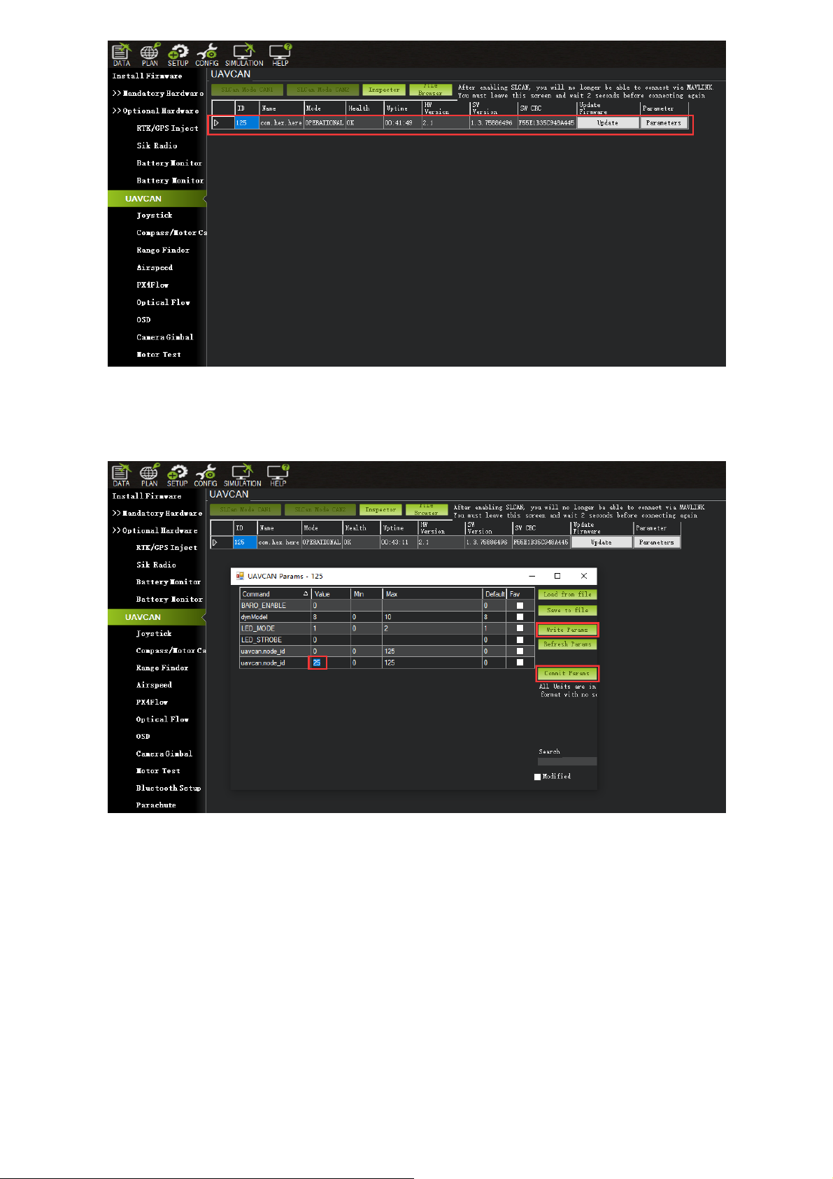
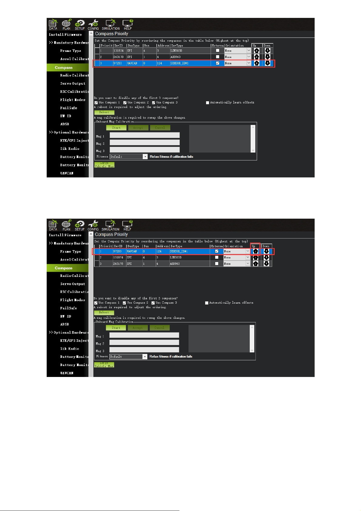
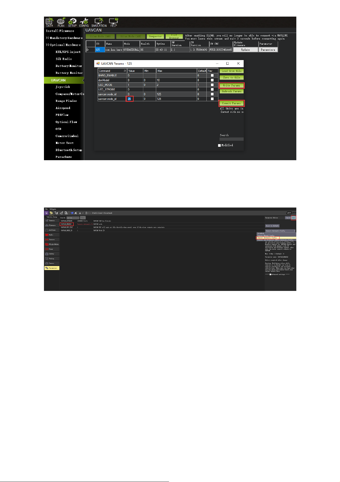
5. Support from ground control software. Future updates will be available from Mission
Planner.
6. Built-in a complete set of Inertial Measurement Unit (compass, gyroscope, and
accelerometer), which satisfy advanced navigation needs.
Specification

Pin Definition Cable Colour
1 VCC_5V Red
2 CAN_H White
3 CAN_L Yellow
4 GND Black
Pinout
Configuration
1. Using Ardupilot Firmware:
Using one Here3:
Connect the 4pin CAN cable connector to CAN1 or CAN2 port on flight controller.
power the flight controller and connect it to Mission Planner. Go to "Config/Tuning > Full
Parameter List" and modify the following paramters:
CAN_D1_PROTOCOL: 1
CAN_D2_PROTOCOL: 1
CAN_P1_DRIVER: 1
CAN_P2_DRIVER: 1
GPS_TYPE: 9
NTF_LED_TYPES: 231
Click "Write Params" when done. CAN functions will be available after rebooting the flight
controller.

Using two Here3:
You need the latest Ardupilot firmware to manually assign different node ids to Here3 to work
properly (node ids are 0-125).
Connect each Here3 4Pin CAN cable to the CAN1 port of the flight controller(one at a time), and
conduct the following procedure. Select "install firmware" from Mission Planner and load the
latest copter and plane firmware.
After successful loading, select the autopilot COM port with 115200 baud rate and click "connect"
at the right-top corner. Go to "Initial Setup - Optional Hardware - UAVCAN", click "SLCan Mode
CAN1".
When the device settings of Here3 pop up, click "Parameters" from the right.

In parameter setting page, change uavcan.node_id to 0-125. Click before entering value. Then,
click "Commit Params" to save the changes and completed manual CAN id allocation.
After manually setting the two Here3 node ids in turn,Connect the two Here3 interfaces to the
flight controller CAN 1 and CAN 2, respectively.
Turn on the flight controller and connect it to Mission Planner. Go to "Config/Tuning > Full
Parameter List" and modify the following paramters:
CAN_D1_PROTOCOL: 1
CAN_D2_PROTOCOL: 1
CAN_P1_DRIVER: 1
CAN_P2_DRIVER: 1
GPS_TYPE: 9
GPS_TYPE2: 9

NTF_LED_TYPES: 231
Click "Write Params" when done. CAN functions will be available after rebooting the flight
controller.
Compass Setting(Using the current stable firmware copter4.0.3,plane4.0.5):
When using Cube Black, the CAN GPS external compass is automatically set to compass 3,
and when using Cube Orange, the CAN GPS external compass is automatically set to
compass 2.
Safety switch is not available in Here3. Safety switch check can be disabled by changing
parameter "BRD_SAFETYENABLE" to 0. Connecting an external safety switch to GPS1
connector is also an alternative option.
If you need to use the external CAN compass as the primary compass, Set the primary compass
to Compass2(CubeOrange) or Compass3(CubeBlack).
Compass Setting(Using the latest version of firmware):
At the time of writing this document, the firmware used for this section is ArduCopter Beta
4.0.4

To use CAN external compass as compass 1, use the up arrow on the right to move the "UAVCAN"
compass to the first place.
Select the compasses that need to be used (or leaving it as default), and then click "Start" to Start
the calibration of the compasses. After the calibration is completed, the compass can be normally
used.

2.Using PX4 firmware:
Current PX4 firmware does not support auto allocating CAN node ID. Manually allocating node ID
needs to be done on latest Ardupilot firmware before using it. Connect the 4pin CAN connector
from Here3 to CAN2 port on autopilot. Select "install firmware" from Mission Planner and load
the latest copter firmware.
After successful loading, select the autopilot COM port with 115200 baud rate and click "connect"
at the right-top corner. Go to "Initial Setup - Optional Hardware - UAVCAN", click "SLCan Mode
CAN1".

When the device settings of Here3 pop up, click "Parameters" from the right.
In parameter setting page, change uavcan.node_id to 0-125. Click before entering value. Then,
click "Commit Params" to save the changes and completed manual CAN id allocation.

Now load PX4 firmware into the autopilot. Connect the 4pin CAN connector from Here3 to CAN1
or CAN2 port on autopilot. Connect to the autopilot and set the parameter "UAVCAN_ENABLE" to
"Sensor Automatic Config". The Here3 will now work.
3. LED Meanings (with ardupilot firmware):
Flashing red and blue: Initializing gyroscopes. Hold the vehicle still and level while it initializes the
sensors.
Flashing blue: Disarmed, no GPS lock found.
Solid blue: Armed with no GPS lock.
Flashing green: Disarmed (ready to arm), GPS lock acquired.
Fast Flashing green: Same as above but GPS is using SBAS.
Solid green - with single long tone at time of arming: Armed, GPS lock acquired. Ready to fly.
Double flashing yellow: Failing pre-arm checks (system refuses to arm). Please check pre-arm
error message.
Single Flashing yellow: Radio failsafe activated.
Flashing yellow - with quick beeping tone: Battery failsafe activated.

Flashing yellow and blue - with high-high-high-low tone sequence (dah-dah-dah-doh): GPS glitch
or GPS failsafe activated.
Flashing red and yellow - with rising tone: EKF or Inertial Nav failure
Flashing purple and yellow: Barometer glitched
Solid Red: Error. Usually due to cannot detect SD card (please try to re-plug or replace SD card),
MTD device, or IMU sensors. Analysis can be found in BOOT.txt in SD card.
Solid Red with SOS tone sequence : SD Card missing (or other SD error like bad format etc.)
Not lighting up: No firmware detected or firmware corrupted.
RTK Use Operation
Base/Rover Survey by Mission Planner
This part of the tutorial uses Mission Planner ground software and Arducopter-4.0.3 flight
firmware for operating instructions.
At the time of writing this document, PX4 firmware does not support CAN RTK yet.
RTK mode requires a base station. The following tutorial Use "Here+" base stations as an
example. Users can also use other uBlox M8P/F9P base stations (such as HerePro, etc.), or
use the local wireless RTK correction service.
To use Here3 on a UAV, you need the following hardware: Computer, telemetry modules, Here3 ,
Base Antenna, Base, Tripod(Stand)

Before using, make sure the hardware are connected correctly: Ground side: The base station
module is connected to the computer port through USB port; a telemetry module is connected to
another USB port of the same computer. UAV side: Here3 is connected to the flight controller
CAN connector; telemetry module is connected to the TELEM interface.
Antenna Placing
Placing the RTK Antenna is very important for getting precise RTK positioning
For the working condition of RTK, there are some special requirements that are more demanding
than regular GPS.
The best environment requires the base and rover antenna to have clear view of the sky that is
30 degrees above horizon. RTK antenna can be elevated but make sure that there are no
obstacles around, such as buildings, trees, cars, and etc.
Example of bad environment: indoors, urban area, forest, near the ground.
Example of good environment: Open spaces, peak of the mountains, roof of the buildings.
Do not place the antenna near electronic devices, as high power electronic devices nearby may
affect the radio frequency noise of GPS signal. Examples are mobile phone base stations, high
voltage transformers, and etc.
Please place the base station in an outdoor environment with sufficient sky coverage to obtain a
good satellite signal. Place the base station on a stable and elevated platform, such as a tripod.

Base Module Setting using Mission Planner
Start with base module setup first. During the base station setup, the rover and the UAV do not
need to be turned on.
Open the Mission Planner ground station software on your computer and go to the "initial setup
→ Optional Hardware → RTK/GPS Inject". You will see the following page:
Select the correct base module com port in the top left corner and click connect. In the SurveyIn
Acc section, enter the absolute geographic accuracy that you expect your Here3 base station to
achieve. In the Time column, enter the minimum survey time you expect. Click on Restart, the
ground station will transfer the data you have entered to the Here3 base module, the base
module will start a new round of surveying. You will see the following page:

During the survey process, the right box will show the current survey status:
Position is invalid: base station has not yet reached a valid location;
In Progress: survey is still in progress;
Duration: The number of seconds that the current surveying task has been executed;
Observation: the number of observations acquired;
Current Acc: Absolute geographic accuracy that the current base station can achieve;
Green bar at the lower part of the Mission Planner page shows the satellites being detected and
the signal strength related to each satellite. At least eight or more satellite signals are guaranteed
to exceed the red line ( Only when the satellite signal exceeds the red line is the effective number
of satellites).
The base station needs a certain amount of time to meet the accuracy requirements of your
input. Testing shows that, in an open area without shelter, to achieve the absolute accuracy of 2m
takes a few minutes; to reach the absolute accuracy of less than 30cm takes around an hour; to
reach the accuracy of 10cm takes a few hours.
It should be noted that the absolute geographic accuracy of the base station here will affect the
absolute geographic accuracy of the rover module without affecting the relative accuracy
between the base station and rover. If your application does not require UAV with high absolute
geographic accuracy, you do not need to set the base station’s precision too high, resulting in
long survey time.
Even if the accuracy of the base station is 1.5 to 2 m, the position accuracy of the rover module
relative to the base station can still reach centimeter level.
After the survey is complete, Mission Planner will display the following page:

In the RTCM box it shows that the base status indicator is green and both the GPS and Glonass
satellite systems are green (if you want to change the satellite system, refer to the following
section). The box on the right says "Position is valid".
To store the current location in the Mission Planner: Click "Save Current Pos", enter a name in the
dialog box, and click "OK". As shown below, you can see your saved location in the list. Click the
"Use" button for the location you saved. The base station will enter the fixed mode and the status
will show "Using FixedLLA". In the future, if you set the base station in the same location, you do
not need to conduct survey again, just click the "Use" button that corresponds to the location you
have saved.
Rover Module and Flight Controller Setup

After the base station is set up, you can turn on the UAV. Using the same Mission Planner to
connect the telemetry module, the base station data will be transmitted through telemetry
module to the Here3 rover module on the UAV. In the Mission Planner main page, you can see
the current GPS status displayed as RTK Float / RTK Fixed / 3D RTK, indicating that the positioning
of the UAV has entered the RTK mode. RTK Float is a floating-point solution; RTK Fixed is a fixed
solution. RTK Fixed mode has a higher accuracy and requires better signal strength. 3D RTK is
unified saying of RTK Float / RTK in the Mission Planner Chinese version.
Single Base to Multiple Rovers
There are 2 methods to do this:
1) Use 1 telemetry to multiple telemetry broadcasting ;or 2) Use multiple 1 to 1 telemetry
modules with USB hub
Ground station configuration: connect all telemetry modules to the computer via USB hub. Open
Mission Planner to locate the base then connect it with flight controllers. Select AUTO connecting
as shown below. All recognized flight controllers on the ports will be connected. You may select
the UAV form the dropdown list below:

If you connected the UAVs with 1 telemetry module, they should share the same COM port:

2020.8.1
Table of contents