Sanav GS-818 User manual

SANAV GS-818
GPS/GSM/GPRS Vehicle Tracker
User Manual
Revision: 1.6.0
Revision Date: 2011/12/10
December 2011 1.6.0
Copyright © 2011 San Jose Technology, Inc. All Rights Reserved.
This document contains information that is the property of SANAV. This document may not be copied, reproduced,
reduced to any electronic medium or machine readable form, or otherwise duplicated, and the information herein may not
be used, disseminated or otherwise disclosed, except with the prior written consent of SANAV

GS-818 GPS/GSM/GPRS Vehicle Tracker User Manual
2 Copyright © 2011 San Jose Technology, Inc. All Rights Reserved.
GS-818 User Documentation
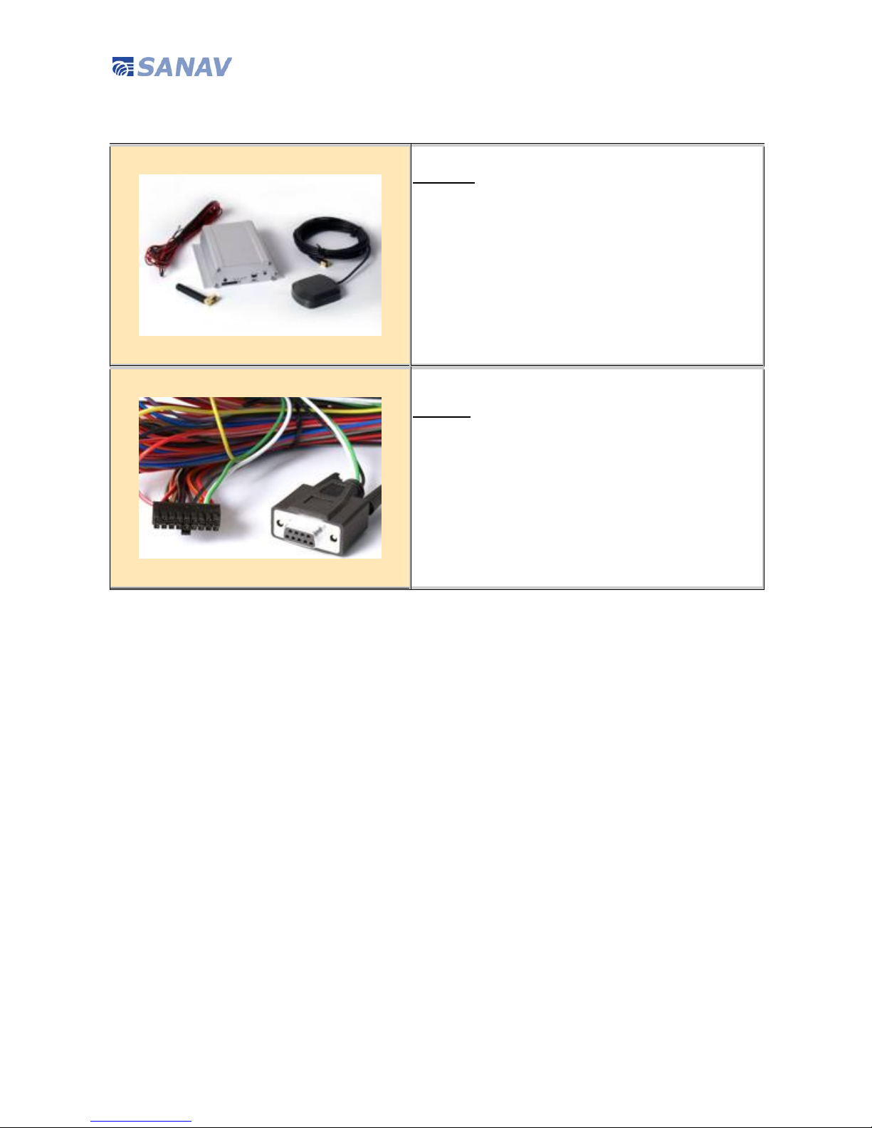
Introduction SANAV GS-818 is specially designed for vehicle tracking applications, equipped with
Siemens GSM module and CSR SiRF Star III GPS Receiver. The rugged metallic
structure is a best match for in-car environments. Opened I/Os are provided for
versatile applications. The user can communicate with the service server through
GPRS/GSM network with real-time tracking through SMS/http/TCP and UDP protocols,
transfer alarms of Emergency, over speed, Geo-fencing…etc, and record the tracking
history stored in internal flash memory if GSM service is not available
This User Manual details the specification, hardware introduction, SMS commands and
Tracker Status of GS-818. If you have any question about the operation of GS-818,
please contact SANAV Customer Service jacky.sun@sanav.com.
Disclaimer This document, and all other related products, such as device, firmware, and software,
is developed by San Jose Technology Inc. thoroughly. At the time of release, it is most
compatible with specified firmware version. Due to the functionalities of the devices
are being developed and improved from time to time, the change in the protocol,
specification, and firmware functions are subjects to change without prior notice.
SANAV is obligated to modify all the documentation without the limitation of time
frame. A change notice shall be released to San Jose Technology Inc. customers upon
the completion of document modification.
San Jose Technology Inc. products are not intended to be used as life support or
rescue equipments. San Jose Technology Inc. is not liable for any loss or injury caused
by using or referencing to any products. Any possible means of using or integrating
San Jose Technology Inc. products shall be avoided.
Copyright Copyright © 2011, San Jose Technology, Inc. All rights reserved.
The information in this publication is proprietary to San Jose Technology, Inc.
No part of this publication may be used, disclosed, reproduced, adapted, translated,
stored in a retrieval system, or transmitted in any form of or by any means, electronic
or mechanical, for any purpose, without the prior written permission of San Jose
Technology, Inc. although every precaution has been taken in the preparation of this
publication, San Jose Technology, Inc., assumes no (i) responsibility for errors or
omissions contained herein or (ii) liability for any damages resulting from the use of
information contained herein. Information in this publication is subject to change
without notice.

GS-818 GPS/GSM/GPRS Vehicle Tracker User Manual
3 Copyright © 2011 San Jose Technology, Inc. All Rights Reserved.
Document Amendments
Revision
Date Comments
1.2.3 2011/4/2
2
N/A
1.6.0 2011/12/
10
1. Jamming Detection added.
2. Park removed.
3. New edition with whole amendments.

GS-818 GPS/GSM/GPRS Vehicle Tracker User Manual
4 Copyright © 2011 San Jose Technology, Inc. All Rights Reserved.
Contents
Hardware General Introduction............................................................... 7
Specification ..................................................................................... 7
Package Contents.............................................................................. 8
Hardware Front View.......................................................................... 9
I/O Serial Color& Pin Assignment......................................................... 9
Hardware Rear View .......................................................................... 9
Hardware Installation Guide ..................................................................10
I/O Serial Pin Definition Standard .......................................................12
I/O Serial Pin Definition 6 Pin Cable ....................................................13
LED Indication..................................................................................14
SMS Command Introduction..................................................................15
Change User Name ..............................................................................16
Change Password.................................................................................17
Request IMEI Number...........................................................................18
Set up APN for GPRS Service.................................................................19
Set up Phone Book List .........................................................................20
Set up Book Mode................................................................................22
Set up Security Phone Number ..............................................................23
Set up Real Time Communication...........................................................24
Set up Route for Data Transmission........................................................25
Set up URL..........................................................................................27
Set up TCP or UDP/IP ...........................................................................28
Set up Auto Report by Time ..................................................................29
Set up Auto Report by Distance .............................................................30
Set up Auto Report by Stationary Times..................................................31
Acquire the Report of Current Position ....................................................33
Angle Report .......................................................................................34
ACC Status Detection ...........................................................................36
ACC Report Interval .............................................................................37
Over Speed Detection...........................................................................38

GS-818 GPS/GSM/GPRS Vehicle Tracker User Manual
5 Copyright © 2011 San Jose Technology, Inc. All Rights Reserved.
Set up Geo-Fence Coordinates...............................................................39
Set up Geo-Fence Coordinates in Degrees with Reference Direction............40
Enable/Disable Geo-Fence Detection.......................................................41
Enable/Disable Specified Geo-Fence Coordinate .......................................42
Enable/Disable All Geo-Fence Coordinates...............................................43
Read Current Status of the Geo-Fence Setting .........................................43
Clear Geo-Fence Setting .......................................................................43
Geo-Fence Alarm Report .......................................................................44
SOS (Emergency/Panic)........................................................................45
Set up SOS Alarm Report Interval ..........................................................46
Set up SOS Phone Book........................................................................47
Jamming Detection ..............................................................................48
Jamming I/O Setup ..............................................................................49
Vibration Setup....................................................................................50
Vibration Enable/Disable .......................................................................51
I/O Input Detection Activation ...............................................................52
Set up I/O Input Status and Interval ......................................................53
I/O Output Activation ...........................................................................54
Output Action Time Definition................................................................55
External Device Setting.........................................................................56
GPRMC Data Log Function .....................................................................57
Define LAUTO Log Interval ....................................................................59
Erase the Logged Data..........................................................................62
Reset to Default Setting........................................................................63
CPOL Mode Setup ................................................................................64
Check the CPOL List .............................................................................65
Setup Extra INFO Bit ............................................................................66
Extra Info bit 0 Description ...................................................................69
Appendix 1: Tracker Status (Event) Message List .....................................70
Appendix 2: GPRMC Data Output Format ................................................72

GS-818 GPS/GSM/GPRS Vehicle Tracker User Manual
6 Copyright © 2011 San Jose Technology, Inc. All Rights Reserved.
GPRMC Data Output Format_ HTTP, TCP/IP or UDP/IP ...........................72
GPRMC Data Output Format_ Barcode Reader (Scanner) .......................74
GPRMC Data Output Format_ RFID Reader...........................................75
GPRMC Data Output Format_ Extra INFO.............................................76
Appendix 3: NMEA 0183 GPRMC Data Format..........................................77
Appendix 4: Common Error Response.....................................................78
Warranty Regulation.............................................................................79

GS-818 GPS/GSM/GPRS Vehicle Tracker User Manual
7 Copyright © 2011 San Jose Technology, Inc. All Rights Reserved.
Hardware General Introduction
Specification
GPS Module
Receiver CSR SiRF star IIITM GPS Receiver
Datum WGS-84
Sensitivity -159dB
Reacquisition <0.1s
Update Rate 1 Hz
Accuracy Average accuracy within 15 meters
GSM Transceivers
GSM Module Siemens BG2-W
General
Antenna
External GSM antenna (SMA Connector);
External GPS antenna (RSMA Connector)
External Power Supply 8-35V DC
Current Consumption
Operation : 42~81mA @ 12V DC
Standby : 8.8~14mA @ 12V DC
Dimension 105(L) x 100(W) x 30(H) mm
I/O
1 x ACC Detection
2 x Output (Max. operating current 300mA, @VIN)
2 x Analog Input (0~40 V DC, Function reserved)
5 x Digital Input (2 Positive 3~40V, 3 Negative 0~0.6V)
Interface
RS-232 ( Support Garmin FMI , Bar Code Reader , RFID
Reader )

GS-818 GPS/GSM/GPRS Vehicle Tracker User Manual
8 Copyright © 2011 San Jose Technology, Inc. All Rights Reserved.
Package Contents
Standard
GS-818 Unit x 1
External GSM Antenna x 1 (stick)
External GPS Antenna x 1 (mouse)
Power Cable x 1
Utility CD x 1 (User Manual, software, USB driver)
Optional
USB Data Cable
I/O Connector Cable
Micro Phone & Button Cable
Firmware Program Cable

GS-818 GPS/GSM/GPRS Vehicle Tracker User Manual
9 Copyright © 2011 San Jose Technology, Inc. All Rights Reserved.
Hardware Front View
I/O Serial Color& Pin Assignment
1
Out1
3
In4_H
5
In5_H
7
In1_L
9
In2_L
11
In
A1
13
In
A2
15
Tx
17
BSL
2
Out2
4
GND
6
ACC
8
GND
10
In3_L
12
GND
14
Call
SOS
16
Rx
18
ORST
Hardware Rear View

GS-818 GPS/GSM/GPRS Vehicle Tracker User Manual
10 Copyright © 2011 San Jose Technology, Inc. All Rights Reserved.
Hardware Installation Guide
1. Please connect the battery cable (BAT) with fuse to the BAT power in
Fuse Box, such as 10A/Interior light shown on the example figure.
CAUTION: DO NOT CONNECT DEVICE POWER TO CAR BATTERY
DIRECTLY TO AVOID DEVICE BURN OUT.
2. For ACC detection, please connect the ACC cable (Pin 6, Input_H,
Brown) to the ACC system in Fuse Box, such as 15A Cigar Lighter
shown on the example figure.

GS-818 GPS/GSM/GPRS Vehicle Tracker User Manual
11 Copyright © 2011 San Jose Technology, Inc. All Rights Reserved.

GS-818 GPS/GSM/GPRS Vehicle Tracker User Manual
12 Copyright © 2011 San Jose Technology, Inc. All Rights Reserved.
I/O Serial Pin Definition Standard
I/O
Description
Color Definition
Power
Voltage IN Red Range: (DC 8~35V)
G Ground Black Ground
1 Output 1 Red/White Range: DC 8~35V (According Voltage IN, maximum:300mA)
2 Output 2 Red/Black Range: DC 8~35V (According to Voltage IN, maximum:300mA)
3
Input 4 High
(alarm4)
Yellow Type: NC or NO
Default: NO
Range: DC 3V-40V, Trigger when pull high
4 Ground Black Ground
5
Input 5 High
(alarm5)
Orange Type: NC or NO
Default: NO
Range: DC 3V-40V, Trigger when pull high
6 ACC Brown Range: DC 3V-40V, Trigger when pull high
7
Input 1 Low
(alarm1)
Blue Type: NC or NO
Default: NO
Range: DC 0V-0.6V
8 Ground Black Ground
9
Input 2 Low
(alarm2)
Purple Type: NC or NO
Default: NO
Range: DC 0V-0.6V
10
Input 3 Low
(alarm3)
Gray Type: NC or NO
Default: NO
Range: DC 0V-0.6V
11 Input A1 Gray/Black Type: I/O Input analog 1
Range: 0V~40V
12 Ground Black Ground
13 Input A2 Gray/White Type: I/O Input analog 2
Range: 0V~40V
Accept Call Press Accept call when someone calls in
14
SOS
Red/Orange
Long Press 3S
Enter SOS/Panic mode
15 Tx(output) White RS-232 TX (2)
16 Rx(input) Green RS-232 RX (3)
17 BSL Pink Boot Scrap Loader control (firmware upgrade only)
18 ORST Red Hardware reset
Note: For Input 1, 2 and 3, only connect to a passive sensor to GND

GS-818 GPS/GSM/GPRS Vehicle Tracker User Manual
13 Copyright © 2011 San Jose Technology, Inc. All Rights Reserved.
I/O Serial Pin Definition 6 Pin Cable
I/O Description
Color Definition
1 Output 1 Red/White Range: DC 8~35V (According Voltage IN, maximum:300mA)
3
Input 4 High
(alarm4)
Yellow Type: NC or NO
Default: NO
Range: DC 3V-40V, Trigger when pull high
6 ACC Brown Range: DC 3V-40V, Trigger when pull high
7 Input 1 Low
(alarm1)
Blue Type: NC or NO
Default: NO
Range: DC 0V-0.6V
Note: Only connect to a passive sensor to GND
8 Ground Black Ground
18 ORST Red Hardware reset

GS-818 GPS/GSM/GPRS Vehicle Tracker User Manual
14 Copyright © 2011 San Jose Technology, Inc. All Rights Reserved.
LED Indication
Events Blue (GPS)
Red (GSM) Red (Power)
Yellow (Status)
Initial Flash every 1s Flash every 1s ON
Power ON ON
GPS Fix ON ON
No GPS Light off ON
GSM in service
(no power saving)
ON and flash
every 3s
ON
GSM in service
(power saving)
ON ON
GSM not in service
Flash ON
No SIM Card or PIN
code required
OFF ON
Data Transmission
ON Flash once when
sending data
Receiving a call OFF ON
Connect to PC
(Utility)
ON ON
Low Power ON ON and flash every
5s
Enter PARK mode ON ON
I/O Triggered ON ON
SOS Triggered ON Flash for several
times
PS1: GS-818 generates loud beep sound when power ON without inserting SIM card.
PS2: When disconnect from PC, the device resets automatically.

GS-818 GPS/GSM/GPRS Vehicle Tracker User Manual
15 Copyright © 2011 San Jose Technology, Inc. All Rights Reserved.
SMS Command Introduction
User can set up the device by entering the command via SMS from a cellular phone. The description and
format of SMS commands will be shown as the following.
1: The default setting:
a. Default ID is “username”. Please read chapter Change User Name to desired ID.
b. Default password is “0000”. Please read chapter Change Password to change the password.
c. There is no number in the default contact. Please read chapter Set up Phone Book List to add the number.
d. Default setting of Auto Report is deactivated. Please read chapter Set up Auto Report by Time
to setup the
regular auto report.
e. Default setting of APN is only suitable for Taiwan GSM network. Please read chapter
Set up APN for GPRS
Service to change the APN.
f. Default setting of URL is http://www.sanav.com/eric-gga/gprs.aspx. Please read chapter Set up URL
to
change the URL.
g. Before doing any setup, please ensure the device is connected with the GSM network. The GSM
LED must light on.
And please note the device is not in SOS/Panic mode.
2: Please note that all the characters which include #, * and comma (,) should be HALFWIDTH form.
3: Please be aware of the upper (capital)/lower cases when entering the SMS command to the device.
4: While typing any setup SMS command, note that NO SPACE is allowed between the characters, comma and signs
in the
SMS.
5: Any setup command must be started with a “#” sign and ended up with a “*” sign.
6: Add or not add the “+ “sign in front of the cellular phone number(s) are both a
cceptable, while the”+” sign should precede
the international call prefixes. The specified international call prefix is required if “+ “sign is not added.
7: The device will update setting Only when the password, username and setup command are all correct. If
the command is not valid, a failure report is going to be sent to the user’s cell phone.
8:
Some PREPAID PHONE CARD SIM modules do not enable or even support GPRS service. Please consult with GSM carrier
for further information.

GS-818 GPS/GSM/GPRS Vehicle Tracker User Manual
16 Copyright © 2011 San Jose Technology, Inc. All Rights Reserved.
Change User Name
Generally, SMS command execution needs correct user name with password, or it will remain the same setting.
The SMS command default user name is “username”. It can be changed by following the command format.
For example, entering the SMS command as the following allows user to change the user name from “username” to a new
user name “sanav”.
Only enter new command with new user name after it has been changed.
Setup format: #「User Name」,「Password」,「Function Code」,「New User Name」*
Command: #username,0000,1,sanav*
Table: User Name Change Format Description
Table: User Name Change Response Description
SMS Text Description
# Start sign.
username Default user name of the device.
0000 Default password.
If you have changed the password, please use the updated one.
1 Mode 1 defines the user name setup mode.
sanav New user name changed by the user.
At the maximum of 16 characters, including a~z,A~Z,0~9, @ - _ / .!%&
* End sign.
Situation Response
Setup Succeeds [username] + Device username is updated.
Setup Fail [username] + Device username setup fail!
Incorrect password [username] + Password setup Fail!
Incorrect username or
command format
[username] + command error

GS-818 GPS/GSM/GPRS Vehicle Tracker User Manual
17 Copyright © 2011 San Jose Technology, Inc. All Rights Reserved.
Change Password
Generally, SMS command execution needs correct user name with password, or it will remain the same setting.
The SMS command default password is “0000”. It can be changed by following the command format.
For example, entering the SMS command as the following allows user to change the password from “0000” to a new
password “1111”.
Only enter command with new password will be valid for setting change after it has been changed.
Setup format:#「User Name」,「Password」,「Function Code」,「New Password」,「New Password」*
Command: #username,0000,2,1111,1111*
Table: Password Change Format Description
Table: Password Change Response Description
SMS Text Description
# Start sign.
username Default user name of the device.
If you have changed the username, please use the updated one.
0000 Default password.
If you have changed the password, please use the updated one.
2 Mode 2 defines the password setup mode.
1111 New password (Please note at the maximum of 4 number)
1111 Reconfirm the password
* End sign.
Situation Response
Setup Succeeds [username] + Device Password is updated.
Setup Fail [username] + Password setup Fail!
Incorrect password [username] + Password setup Fail!
Incorrect username or SMS
format
[username] + command error
Emergency Mode [username] + Username, in emergency, setup stop.

GS-818 GPS/GSM/GPRS Vehicle Tracker User Manual
18 Copyright © 2011 San Jose Technology, Inc. All Rights Reserved.
Request IMEI Number
IMEI stands for International Mobile Equipment Identification, a unique number for identifying mobile devices validity in
GSM network.
As above stated, each device has a unique IMEI number. Entering the SMS command as the following allows user to check
the IMEI number of the device for network registration and tracking.
Setup format:#「User Name」,「Password」,「Function Code」*
Command: #username,0000,imei*
Table: IMEI Inquiry Format Description
Table: IMEI Inquiry Response Description
SMS Text Description
# Start sign.
username Default user name of the device.
If you have changed the username, please use the updated one.
0000 Default password.
If you have changed the password, please use the updated one.
imei Mode imei defines IMEI inquiry mode.
* End sign.
Situation Response
Setup Succeeds [username] + “,[imei]”
Incorrect password [username] + Password setup Fail!
Incorrect username or
command format
[username] + command error

GS-818 GPS/GSM/GPRS Vehicle Tracker User Manual
19 Copyright © 2011 San Jose Technology, Inc. All Rights Reserved.
Set up APN for GPRS Service
Access Point Name (APN) is a protocol that typically allows device to access the internet using the mobile phone network.
It is a network identifier used by a mobile device when connecting to a GSM carrier. The carrier will then examine this
identifier to determine what type of network connection should be created.
For uploading the data to a web server, a set of GPRS APN from your GSM network is required. Various GSM network
provides different GPRS APN settings. Please consult with GMS carrier about the APN setting. If the user name and
password of APN are indefinite or showed in blank, just leave the parameters empty (no space) with comma “,”. User can
follow the Setup Format below to setup the APN that is provided by your GSM carrier.
Setup format:#「User Name」,「Password」,「Function Code」,「GPRS Access Point Name」,「APN User Name」,「APN
Password」*
Command: #username,0000,3,internet,user,password*
By the way, Some PREPAID PHONE CARD SIM modules do not enable or even support GPRS service. Please consult with
GSM carrier for further information.
Table: APN Setup Format Description
Table: APN Setup Response Description
SMS Text Description
# Start sign.
username Default user name of the device.
If you have changed the username, please use the updated one.
0000 Default password.
If you have changed the password, please use the updated one.
3 Mode 3 defines the APN setup mode.
Internet Name of APN
user Username of APN
password Password of APN
* End sign.
Situation Response
Setup Succeeds [username] + Device GPRS APN is updated.
Setup Fail [username] + Device GPRS APN setup Fail!
Incorrect password [username] + Password setup Fail!
Incorrect username or
command format
[username] + command error

GS-818 GPS/GSM/GPRS Vehicle Tracker User Manual
20 Copyright © 2011 San Jose Technology, Inc. All Rights Reserved.
Set up Phone Book List
There are three main purposes of Phone Book List setup:
1. Backup route: As a backup route when the data is not able to send to the server. The data will be sent to 1st cellular
number PH-01 only.
2. SOS Alarm Route: When the device is in SOS mode, it will send SOS alarm report to the phone numbers in the list.
3. SMS Data Route: When the data route is set to SMS only, the device will send GPRMC data to the cellular phone
numbers in the list by SMS message. (Please refer to Set up Route for Transmitting Data)
Use this SMS command to set up the cellular phone book (Max. of 3 numbers) as the following format:
Setup format: #「User Name」,「Password」,「Function Code」,「PH-01」,「PH-02」,「PH-03」,「Bookmode Code」*
Command: #username,0000,5,+886123456789,+492234567890,+866323456789,7*
Note1: Add or not add the “+ “sign in front of the cellular phone number(s) are both acceptable, while the”+” sign should
precede the international call prefixes.
Note2: When Report route is set at 4. SMS MODE without setting up Bookmode Code, the device will assign all the
numbers in Phone Book List to receive SMS message and GPS data. The default Bookmode is 1 when only PH-01 is set,
the default Bookmode is 3 when both PH-01 and PH-02 are set, and the default Bookmode is 7 when all the numbers
PH-01, PH-02 and PH-03 are set. Please refer to Table: Phone Number List Setup Format Description for detail.
Table of contents
Other Sanav GPS manuals