Hexagon CPT7 User manual

CPT7 and CPT7700
Installation and Operation
User Manual
CPT7 and CPT7700 Installation and Operation User Manual v9 May 2021

CPT7 and CPT7700 Installation and Operation User Manual v9 2
CPT7 and CPT7700 Installation and Operation User Manual
Publication Number: OM-20000179
Revision Level: v9
Revision Date: May 2021
Firmware Version: CPT7 7.08.02 / SC7PR0802RN0000
Warranty
NovAtel Inc. warrants that its GNSS products are free from defects in materials and workmanship, subject to
the conditions set forth on our web site: novatel.com/products/novatel-warranty-and-return-policies.
Return instructions
To return products, refer to the instructions found at: novatel.com/products/novatel-warranty-and-return-
policies.
Proprietary Notice
ALIGN, GLIDE, Inertial Explorer, NovAtel, OEM7, RTK ASSIST, SPAN, STEADYLINE, TerraStar, VEXXIS
and Waypoint are trademarks of NovAtel, Inc., entities within the Hexagon Autonomy & Positioning division,
their affiliated entities, and/or their licensors. All other trademarks are properties of their respective owners.
©2021 NovAtel Inc. All rights reserved. NovAtel is part of Hexagon. NovAtel makes no representation or
warranty regarding the accuracy of the information in this publication. This document gives only a general
description of the product(s) or service(s) offered by NovAtel and, except where expressly provided otherwise,
shall not form part of any contract. Such information, the products and conditions of supply are subject to
change without notice.

CPT7 and CPT7700 Installation and Operation User Manual v9 3
Table of Contents
Figures
Tables
CPT7 Notices
Customer Support
Chapter 1 CPT7 Overview
1.1 CPT7 Connectors 20
1.2 CPT7 LEDs 21
1.3 Fundamentals of GNSS+INS 24
Chapter 2 CPT7 Installation
2.1 Shipping Box 26
2.2 Additional Equipment Required 26
2.3 Optional Accessories 26
2.4 CPT7 Cables 26
2.5 Selecting a GNSS Antenna 27
2.6 Choosing a Coaxial Cable 28
2.7 Power Supply Requirements for the CPT7 28
2.8 CPT7 Installation Overview 29
2.9 Mounting the GNSS Antenna 31
2.9.1 Antenna LNA Power 31
2.10 Mount the CPT7 31
2.10.1 Securing the CPT7 32
2.10.2 Secure the CPT7 Using the Adapter Plate 33
2.11 Connect the CPT7 to Data Communication Equipment 36
2.11.1 Serial Ports 36
2.11.2 USB Ports 37
2.11.3 Ethernet Port 37
2.11.4 CAN Bus Port 37
2.12 Connect I/O Signals to the CPT7 38
2.13 Connect Power to the CPT7 38
2.13.1 Fuse for the Power Supply 38
2.13.2 Vehicle Installation 39
2.14 Check that the CPT7 is Operating 40
Chapter 3 OEM7 Receiver Operation
3.1 Communications with the Receiver 41
3.1.1 USB Communications 42
3.1.2 Serial Port Communications 42
3.1.3 Ethernet Communications 43

CPT7 and CPT7700 Installation and Operation User Manual v9 4
3.1.4 ICOM Communications 44
3.1.5 CAN Bus Communications 44
3.2 Getting Started 45
3.2.1 Communicating with the Receiver 45
3.3 Transmitting and Receiving Corrections 45
3.3.1 Defining Antenna and Base Antenna 47
3.3.2 Base Station Configuration 47
3.3.3 Rover Station Configuration 48
3.3.4 Configuration Notes 49
3.4 GLIDE 49
3.4.1 Dual-Frequency GLIDE 50
3.4.2 PDP and GLIDE Configurations 50
3.5 STEADYLINE 50
3.5.1 Prefer Accuracy 51
3.6 Enabling SBAS Positioning 51
3.7 Enabling PPP 52
3.7.1 TerraStar Subscriptions 52
3.7.2 Veripos Subscriptions 54
3.8 RTK ASSIST 54
3.9 Transferring Time Between Receivers 55
3.9.1 GPS to Receiver Time Synchronization 55
3.9.2 Time Definitions 55
3.9.3 Procedures to Transfer Time 56
3.10 Interference Toolkit 60
3.10.1 Monitoring GNSS Signals 60
3.10.2 Disable/Enable Detection 62
3.10.3 Monitoring Signals Using a Command Line 62
3.10.4 Monitoring Signals Using NovAtel Application Suite 63
3.10.5 Remove Interference Signals 63
3.10.6 Interference Toolkit Commands and Logs 64
3.11 Logging and Retrieving Data Overview 65
3.11.1 Pass-Through Logging 65
3.11.2 Saving Logs to a File 65
3.11.3 Logging to Internal Memory 66
3.11.4 Access CPT7 Internal Memory with a Computer 67
3.11.5 Repair Errors on the CPT7 Internal Memory 68
3.11.6 Logging Using NovAtel Application Suite or Setup & Monitor (Web) 68
3.12 Additional Features and Information 69
3.12.1 Strobes 69
Chapter 4 SPAN Operation
4.1 Definition of Reference Frames Within SPAN 70
4.1.1 The Local-Level Frame (ENU) 70
4.1.2 The IMU Body Frame 71
4.1.3 The Vehicle Frame 72
4.1.4 The User Output Frame 72
4.2 SPAN Translations and Rotations 72

CPT7 and CPT7700 Installation and Operation User Manual v9 5
4.2.1 Translational Offsets 73
4.2.2 Rotational Offsets 74
4.3 Software Configuration 76
4.3.1 GNSS Configuration 76
4.3.2 INS Profiles 76
4.3.3 Configure the CPT7 IMU Data Rate 77
4.3.4 SPAN Configuration for CPT7 78
4.3.5 Importance of RBV Calibration 80
4.4 Real-Time Operation 82
4.4.1 System Start-Up and Alignment Techniques 83
4.4.2 INSSeed / Fast INS Initialization 85
4.4.3 Navigation Mode 87
4.4.4 Data Collection 87
4.4.5 Body to Vehicle Frame Rotation Calibration Routine 89
4.4.6 Multi-Line Body to Vehicle Frame Rotation Calibration Routine 90
4.5 Distance Measurement Instrument 91
4.5.1 DMI Communication 92
4.5.2 DMI Connection 92
4.5.3 DMI Requirements 92
4.5.4 DMI Connected to a CPT7 93
4.5.5 DMI Command Compatibility 95
4.5.6 DMI Troubleshooting 96
4.6 Synchronizing External Equipment 96
4.6.1 Configuring an Input Strobe 96
4.7 Adding Timed Sensor Triggers 97
4.7.1 Configuring the Hardware 97
4.7.2 Configuring the Software 98
4.7.3 Using Timed Event Pulses 98
4.7.4 Recording Incoming Sensor Events 98
4.8 Azimuth Sources on a SPAN System 98
4.8.1 Course Over Ground 98
4.8.2 Inertial Azimuth 99
4.8.3 ALIGN Azimuth 99
4.9 Data Collection for Post Processing 99
4.10 Variable Lever Arm 100
4.10.1 Reference Frame Description 100
4.10.2 How to Use Variable Lever Arm 103
4.11 Relative INS 105
4.11.1 Configure Relative INS 106
Chapter 5 CPT7 with Dual Antenna
5.1 Installation 108
5.2 Configuring ALIGN with SPAN 110
5.3 Configuring SPAN with ALIGN 111
5.3.1 Aided Transfer Alignment – ALIGN Injected Azimuth 112
5.3.2 Unaided Alignment 112
5.3.3 Automatic Alignment Mode – Automatic Alignment (default) 112

CPT7 and CPT7700 Installation and Operation User Manual v9 6
5.4 SPAN ALIGN Attitude Updates 112
Chapter 6 Ethernet Configuration
6.1 Required Hardware 113
6.2 Static IP Address Configuration 113
6.2.1 Static IP Address Configuration—Receiver 114
6.2.2 Static IP Address Configuration—Windows 7 115
6.2.3 Confirming Ethernet Setup 115
6.3 Dynamic IP Address Configuration 116
6.4 Base/Rover Configuration through Ethernet Connectivity 117
6.5 Large Ethernet Port Data Throughput 118
Chapter 7 NTRIP Configuration
7.1 NTRIP Configuration Over Ethernet 119
Chapter 8 CAN Bus
8.1 Default Configuration 122
8.2 Configuring the CAN Bus 122
8.2.1 Configuration Notes 122
8.2.2 Example of Enabling the CAN Bus 123
8.2.3 Example of Modifying the CAN Bus Parameters 123
8.2.4 Example of Detecting an Address Claim Failure and Reconfiguring 123
8.2.5 Address Claim Procedure 123
8.3 NMEA2000 Logging 124
8.3.1 Example of NMEA2000 Log Configuration 124
8.4 Corrections Over CAN 125
8.4.1 Example for Receiving Corrections from Any Source 125
8.4.2 Example for Transmitting Corrections to 0x1C Node 125
8.5 NovAtel Messages Over CAN 125
8.6 Configuring OEM7 Receivers to Use OEM6 CAN Settings 126
8.6.1 Configuration on OEM6 126
8.6.2 Configuration on OEM7 126
Chapter 9 Built-In Status Tests
9.1 Receiver Status Word 128
9.2 RXSTATUSEVENT Log 128
9.3 RXSTATUS Log 129
9.3.1 Status Word 129
9.3.2 Error Word 129
9.3.3 Status Code Arrays 130
9.3.4 Receiver Status Code 131
9.3.5 Auxiliary Status Codes 131
9.3.6 Set and Clear Mask for all Status Code Arrays 131
Chapter 10 Troubleshooting
10.1 Examining the RXSTATUS Log 133

CPT7 and CPT7700 Installation and Operation User Manual v9 7
10.2 Examining the AUX1 Status Word 136
10.3 High Temperature Environments 137
10.3.1 Indicators of an Error State 137
10.3.2 Recovering from a Temperature Status Error 137
10.3.3 Mitigating High Receiver Temperature 137
10.3.4 Monitoring the Receiver Temperature 138
10.4 Safe Mode 139
10.4.1 Reset Loop Detection 139
10.4.2 Recovery Steps 139
Chapter 11 NovAtel Firmware and Software
11.1 Firmware Updates and Model Upgrades 140
11.1.1 Firmware Updates 140
11.1.2 Model Upgrades 140
11.2 Authorization Code 141
11.3 Downloading Firmware Files 141
11.3.1 Format of Firmware Files 142
11.4 Updating or Upgrading Using the WinLoad Utility 142
11.4.1 Using the WinLoad Utility 142
11.5 Updating the Firmware Using NovAtel Application Suite 144
11.6 Updating the Firmware Using Setup & Monitor (Web) 145
11.7 Updating Using SoftLoad Commands 145
11.7.1 SoftLoad Commands and Logs 146
11.7.2 Working With S-Records 146
11.7.3 Sending Firmware Data 147
11.7.4 SoftLoad Update Method 148
11.7.5 SoftLoad Errors 150
11.8 Upgrading Using an Auth-Code 151
11.8.1 Entering an Auth-Code Using NovAtel Application Suite 151
11.8.2 Entering an Auth-Code Using Setup & Monitor (Web) 151
11.8.3 Entering an Auth-Code Using the Command Line 151
APPENDIX A CPT7 Technical Specifications
A.1 CPT7 Performance Specifications 154
A.2 CPT7700 Performance Specifications 157
A.3 CPT7 IMU Performance Specifications 160
A.4 CPT7 Mechanical Specifications 161
A.5 CPT7 Electrical and Environmental Specifications 165
A.6 CPT7 Data Communication Specifications 168
A.7 CPT7 Strobe Specifications 169
A.8 CPT7 Connectors 170
A.9 CPT7 I/O1 Cable 172
A.9.1 Custom Cable Recommendations 173
A.10 CPT7 I/O2 Cable 174
A.10.1 Custom Cable Recommendations 175

CPT7 and CPT7700 Installation and Operation User Manual v9 9
Figures
Figure 1: CPT7 Receiver 20
Figure 2: CPT7700 Receiver 20
Figure 3: CPT7 Status Indicators 22
Figure 4: Typical Installation of a CPT7 System 29
Figure 5: Typical Installation of a CPT7700 System 30
Figure 6: Default RBV Configuration 32
Figure 7: CPT7 Adapter Plate 34
Figure 8: Offset from the CPT7 to the SPAN-CPT 35
Figure 9: Offset from the CPT7 to the SPAN-IGM-S1 36
Figure 10: Fuse for CPT7 Power Supply 39
Figure 11: Dedicated Battery for the CPT7 40
Figure 12: Basic CPT7 Connection Interfaces (example) 41
Figure 13: Basic Differential Setup 46
Figure 14: Positioning Change Without STEADYLINE 51
Figure 15: STEADYLINE Prefer Accuracy 51
Figure 16: Transfer COARSE Time from Fine Clock to Cold Clock Receiver 57
Figure 17: Transfer FINE Time from Fine Clock to Cold Clock Receiver 58
Figure 18: Transfer FINE Time from Fine Clock to Warm Clock Receiver 59
Figure 19: 1 PPS Alignment 59
Figure 20: Local-Level Frame (ENU) 71
Figure 21: IMU Body Frame Marking 71
Figure 22: Vehicle Frame 72
Figure 23: IMU to Antenna Translation Offset 73
Figure 24: CPT7 to Antenna Offset 79
Figure 25: Rear View of CPT7 – Mounting Plate is not Flat 81
Figure 26: Side View of CPT7 – Vehicle is not Level 81
Figure 27: Top View of CPT7 – CPT7 Misalignment 81
Figure 28: Multi-Line IMU Body to Vehicle Calibration 90
Figure 29: Kistler WPT 92
Figure 30: DMI to CPT7 Setup 94
Figure 31: Sample Configuration 102
Figure 32: Operating Gimbal 103
Figure 33: Relative INS Example 106
Figure 34: SPAN – CPT7700 Dual Antenna Installation 109
Figure 35: SPAN – CPT7 Dual Antenna Installation 110

Figures
CPT7 and CPT7700 Installation and Operation User Manual v9 10
Figure 36: Cross-Over Ethernet Cable Configuration—OEM7 Receiver 114
Figure 37: Dynamic IP Address Configuration through a DHCP Server—OEM7 Receiver 116
Figure 38: Base/Rover Ethernet Setup—OEM7 Receiver 117
Figure 39: NTRIP System 119
Figure 40: Location of Receiver Status Word 129
Figure 41: Reading the Bits in the Receiver Status Word 129
Figure 42: Location of Receiver Error Word 130
Figure 43: Reading the Bits in the Receiver Error Word 130
Figure 44: Status Code Arrays 131
Figure 45: WinLoad’s Open Window 143
Figure 46: Open File in WinLoad 143
Figure 47: COM Port Setup 144
Figure 48: CPT7 Dimensions 162
Figure 49: CPT7700 Dimensions 163
Figure 50: CPT7/CPT7700 Center of Navigation 164
Figure 51: Fischer Core 16 Pin Connector 170
Figure 52: CPT7 I/O1 Cable 172
Figure 53: CPT7 I/O2 Cable 174
Figure 54: Plot of Good and Poor Antenna Phase Center Variation over Elevation Angle 0-90° 184

CPT7 and CPT7700 Installation and Operation User Manual v9 11
Tables
Table 1: CPT7 Connectors 21
Table 2: CPT7 and CPT7700 Status Indicators 22
Table 3: PWR (Power) LED 22
Table 4: POS (Positioning) LED 22
Table 5: INS LED 23
Table 6: LOG (Onboard Storage) LED 23
Table 7: CPT7 Cables 27
Table 8: Fuse/Holder Recommendations 39
Table 9: Serial Ports Supported 43
Table 10: OEM7 INS Profiles 76
Table 11: Inertial Solution Status 82
Table 12: NVM Seed Indication 87
Table 13: Solution Parameters 87
Table 14: Kistler to NovAtel Wheel Sensor Cable Connections 93
Table 15: DMI Command and Log Compatibility 95
Table 16: Valid Event Inputs and Outputs for Timed Sensor Triggers 97
Table 17: Logs with Azimuth Data 99
Table 18: Logs used with Variable Lever Arm 104
Table 19: Commands used with Variable Lever Arm 104
Table 20: Default NAME 122
Table 21: Troubleshooting Based on Symptoms 132
Table 22: Resolving a Receiver Error Word 133
Table 23: Resolving an Error in the Receiver Status Word 135
Table 24: Resolving an Error in the AUX1 Status Word 136
Table 25: CPT7 Physical Description 153
Table 26: CPT7 Receiver Performance 154
Table 27: CPT7700 Receiver Performance 157
Table 28: CPT7 IMU Performance 160
Table 29: CPT7 Environmental Specifications 165
Table 30: CPT7 Power Requirements 165
Table 31: CPT7 RF Input/LNA Power Output 165
Table 32: CPT7 Wheel Sensor Input Signal Levels 166
Table 33: Data Communications Interfaces 168
Table 34: CPT7 Strobes Description 169
Table 35: CPT7 Strobe Electrical Specifications 169

Tables
CPT7 and CPT7700 Installation and Operation User Manual v9 12
Table 36: IO1 Pin Out 170
Table 37: IO2 Pin Out 171
Table 38: CPT7 I/O1 Cable Pinout 172
Table 39: I/O1 Connector 173
Table 40: CPT7 I/O2 Cable Pinout 174
Table 41: IO2 Connector 175
Table 42: Physical Specifications 176
Table 43: Power Requirements 176
Table 44: Signals Tracked 176
Table 45: RF Input 177
Table 46: COM Port Communication 178
Table 47: I/O Strobes 178
Table 48: Features 178
Table 49: OEM7 Receivers 179
Table 50: GNSS Antennas 180
Table 51: CPT7 Cables 181
Table 52: GNSS Antenna Cables 181
Table 53: CPT7 Mounting Accessories 181

CPT7 and CPT7700 Installation and Operation User Manual v9 13
CPT7 Notices
The following notices apply to the CPT7 and CPT7700.
Changes or modifications to this equipment, not expressly approved by NovAtel Inc., could void the
user’s authority to operate this equipment.
FCC
The devices covered by this manual comply with part 15 of the FCC Rules. Operation is subject to the
following two conditions: (1) this device may not cause harmful interference, and (2) this device must accept
any interference received, including interference that may cause undesired operation.
The equipment listed has been tested and found to comply with the limits for a Class B digital device, pursuant
to part 15 of the FCC Rules. The Class B limits are designed to provide reasonable protection against harmful
interference in a residential installation. The equipment listed generates, uses, and can radiate radio
frequency energy and, if not installed and used in accordance with the instructions, may cause harmful
interference to radio communications. However, there is no guarantee that interference will not occur in a
particular installation. If this equipment does cause harmful interference to radio or television reception, which
can be determined by turning the equipment off and on, the user is encouraged to try to correct the
interference by one or more of the following measures:
lReorient or relocate the receiving antenna
lIncrease the separation between the equipment and the receiver
lConnect the equipment to an outlet on a circuit different from that to which the receiver is connected
lConsult the dealer or an experienced radio/TV technician for help
To maintain compliance with the limits of a Class B digital device, you must use shielded interface
cables.
Innovation, Science and Economic Development (ISED) Canada
CPT7 Class B digital device complies with Canadian ICES-003.
CPT7 appareils numérique de la classe B sont conforme à la norme NMB-003 du Canada.
European Union (EU)
Hereby, NovAtel Inc. declares that the radio equipment type CPT7 GNSS receiver is in compliance with
Directive 2014/53/EU
The full text of the EU Declaration of Conformity may be obtained from the NovAtel website at:
novatel.com/products/novatel-compliance/eu-declaration-of-conformity.
WEEE
If you purchased your CPT7 in Europe, please return it to your dealer or supplier at the end of life. The
objectives of the European Community's environment policy are, in particular, to preserve, protect and
improve the quality of the environment, protect human health and utilise natural resources prudently and
rationally. Sustainable development advocates the reduction of wasteful consumption of natural resources
and the prevention of pollution. Waste Electrical and Electronic Equipment (WEEE) is a regulated area. Where

CPT7 Notices
CPT7 and CPT7700 Installation and Operation User Manual v9 14
the generation of waste cannot be avoided, it should be reused or recovered for its material or energy. WEEE
products may be recognized by their wheeled bin label ( ).
See novatel.com/products/novatel-compliance/novatel-environmental-compliance for more information.
RoHS
CPT7 GNSS receivers are in conformity with Directive 2011/65/EU of the European Parliament and of the
Council of 8 June 2011 on the restriction of the use of certain hazardous substances in electrical and
electronic equipment.
CPT7 International Approval
Eurasian Economic Community
Armenia, Belarus, Kazakhstan, Kyrgyzstan and Russia

CPT7 and CPT7700 Installation and Operation User Manual v9 15
Customer Support
NovAtel Knowledge Base
If you have a technical issue, visit the NovAtel Support page at novatel.com/support. Through the Support
page, you can contact Customer Support, find papers and tutorials or download the latest firmware. To access
the latest user documentation, visit docs.novatel.com/OEM7.
Before Contacting Customer Support
Before contacting NovAtel Customer Support about a software problem, perform the following steps:
If logging data over an RS-232 serial cable, ensure that the configured baud rate can support the data
bandwidth (see SERIALCONFIG command). NovAtel recommends a minimum suggested baud rate
of 230400 bps.
1. Log the data suggested in the appropriate Troubleshooting Logs section to a file on your computer for 15
minutes.
lGeneral Troubleshooting Logs on the next page
lTracking and Interference Troubleshooting Logs on the next page
lSPAN Troubleshooting Logs on page17
lRTK Troubleshooting Logs on page17
lPPP Troubleshooting Logs on page18
lALIGN Troubleshooting Logs on page18
3. You can also issue a FRESET command to the receiver to clear any unknown settings.
The FRESET command will erase all user settings. You should know your configuration (by
requesting the RXCONFIGA log) and be able to reconfigure the receiver before you send the
FRESET command.
If you are having a hardware problem, send a list of the troubleshooting steps taken and the results.
Contact Information
Log a support request with NovAtel Customer Support using one of the following methods:
Log a Case and Search Knowledge:
Website: novatel.com/support
Log a Case, Search Knowledge and View Your Case History: (login access required)
Web Portal: https://novatelsupport.force.com/community/login
E-mail:

Customer Support
CPT7 and CPT7700 Installation and Operation User Manual v9 16
Telephone:
U.S. and Canada:1-800-NOVATEL (1-800-668-2835)
International:+1-403-295-4900
General Troubleshooting Logs
LOG RXSTATUSB ONCHANGED
LOG RAWEPHEMB ONNEW
LOG GLORAWEPHEMB ONNEW
LOG BESTPOSB ONTIME 1
LOG RANGEB ONTIME 1
LOG RXCONFIGA ONCE
LOG VERSIONA ONCE
LOG LOGLISTA ONCE
LOG PORTSTATSA ONTIME 10
LOG PROFILEINFOA ONCE
LOG HWMONITORA ONTIME 10
Tracking and Interference Troubleshooting Logs
LOG VERSIONA ONCE
LOG RXCONFIGA ONCE
LOG CHANCONFIGLISTB ONCE
LOG PASSTHROUGHA ONNEW
LOG RXSTATUSB ONCHANGED
LOG CLOCKSTEERINGB ONCHANGED
LOG RAWEPHEMB ONNEW
LOG GLORAWEPHEMB ONNEW
LOG GALINAVRAWEPHEMERISB ONNEW
LOG BDSEPHEMERISB ONNEW
LOG QZSSEPHEMERISB ONNEW
LOG NAVICEPHEMERISB ONNEW
LOG RAWALMB ONNEW
LOG GLORAWALMB ONNEW
LOG GALALMANACB ONNEW
LOG BDSALMANACB ONNEW
LOG QZSSALMANACB ONNEW
LOG NAVICALMANACB ONNEW
LOG IONUTCB ONNEW
LOG GLOCLOCKB ONNEW
LOG GALCLOCKB ONNEW
LOG BDSCLOCKB ONNEW
LOG TRACKSTATB ONTIME 1
LOG RANGEB ONTIME 1
LOG BESTPOSB ONTIME 1
LOG SATVIS2B ONTIME 30
LOG ITDETECTSTATUSB ONCHANGED
For dual antenna receivers, add these logs:
LOG TRACKSTATB_1 ONTIME 1
LOG RANGEB_1 ONTIME 1

Customer Support
CPT7 and CPT7700 Installation and Operation User Manual v9 17
For interference issues add this log.
LOG ITPSDDETECTB ONNEW
For interference issues, when you have enough datalink bandwidth to handle large logs, add this log:
LOG ITPSDFINALB ONNEW
SPAN Troubleshooting Logs
LOG RXSTATUSB ONCHANGED
LOG RAWEPHEMB ONNEW
LOG GLORAWEPHEMB ONNEW
LOG BESTPOSB ONTIME 1
LOG RANGEB ONTIME 1
LOG RXCONFIGA ONCE
LOG VERSIONA ONCE
LOG RAWIMUSXB ONNEW
LOG INSUPDATESTATUSB ONCHANGED
LOG INSPVAXB ONTIME 1
LOG INSCONFIGA ONCHANGED
LOG BESTGNSSPOSB ONTIME 1
RTK Troubleshooting Logs
LOG RXSTATUSB ONCHANGED
LOG RAWEPHEMB ONNEW
LOG GLORAWEPHEMB ONNEW
LOG QZSSRAWEPHEMB ONNEW
LOG BDSRAWNAVSUBFRAMEB ONNEW
LOG GALFNAVRAWEPHEMERISB ONNEW
LOG GALINAVRAWEPHEMERISB ONNEW
LOG RANGEB ONTIME 1.0
LOG BESTPOSB ONTIME 1.0
LOG RXCONFIGB ONCE
LOG VERSIONB ONCE
LOG TRACKSTATB ONTIME 1.0
LOG RTKPOSB ONTIME 1.0
LOG MATCHEDPOSB ONNEW
LOG MATCHEDSATSB ONNEW
LOG RTKSATSB ONTIME 1.0
LOG PSRPOSB ONTIME 1.0
LOG RAWALMB ONNEW
LOG IONUTCB ONNEW
LOG GLORAWALMB ONNEW
LOG GLOCLOCKB ONNEW
LOG PASSTHROUGHB ONNEW
LOG CLOCKMODELB ONTIME 1.0
LOG REFSTATIONB ONNEW
LOG RTKVELB ONTIME 1.0

Customer Support
CPT7 and CPT7700 Installation and Operation User Manual v9 18
PPP Troubleshooting Logs
LOG RXSTATUSB ONCHANGED
LOG RAWEPHEMB ONNEW
LOG GLORAWEPHEMB ONNEW
LOG QZSSRAWEPHEMB ONNEW
LOG BDSRAWNAVSUBFRAMEB ONNEW
LOG GALFNAVRAWEPHEMERISB ONNEW
LOG GALINAVRAWEPHEMERISB ONNEW
LOG RANGEB ONTIME 1.0
LOG BESTPOSB ONTIME 1.0
LOG RXCONFIGB ONCE
LOG VERSIONB ONCE
LOG TRACKSTATB ONTIME 1.0
LOG LBANDTRACKSTATB ONTIME 1.0
LOG PPPPOSB ONTIME 1.0
LOG PPPSATSB ONTIME 1.0
LOG TERRASTARINFOB ONCHANGED
LOG TERRASTARSTATUSB ONCHANGED
LOG PSRPOSB ONTIME 1.0
LOG ALMANACB ONNEW
LOG IONUTCB ONNEW
LOG GLORAWALMB ONNEW
LOG GLOCLOCKB ONNEW
LOG LBANDBEAMTABLEB ONCHANGED
ALIGN Troubleshooting Logs
LOG RXSTATUSB ONCHANGED
LOG RAWEPHEMB ONNEW
LOG GLORAWEPHEMB ONNEW
LOG BESTPOSB ONTIME 1
LOG RANGEB ONTIME 1
LOG RXCONFIGA ONCE
LOG VERSIONA ONCE
LOG LOGLISTA ONCE
LOG PORTSTATSA ONTIME 10
LOG ALIGNBSLNENUB ONNEW
LOG ALIGNBSLNXYZB ONNEW
LOG ALIGNDOPB ONNEW
LOG HEADING2B ONNEW
LOG MASTERPOSB ONNEW
LOG ROVERPOSB ONNEW — This log can only be output if you have Y model ALIGN
LOG HEADINGSATSA ONNEW — This log can only be output on the ALIGN rover
LOG DUALANTENNAHEADINGB ONTIME 1.0

CPT7 and CPT7700 Installation and Operation User Manual v9 19
Chapter 1 CPT7 Overview
SPAN GNSS+INS technology from Hexagon | NovAtel brings together two very different but complementary
positioning and navigation systems namely Global Navigation Satellite System (GNSS) and an Inertial
Navigation System (INS). By combining the best aspects of GNSS and INS into one system, SPAN
technology is able to offer a solution that is more accurate and reliable than either GNSS or INS could provide
alone. The combined GNSS+INS solution has the advantage of the absolute accuracy available from GNSS
and the continuity of INS through traditionally difficult GNSS conditions.
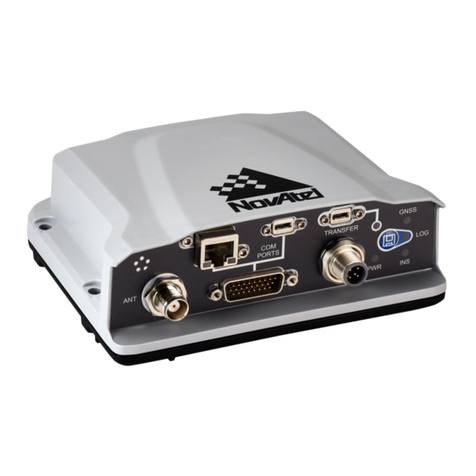
NovAtel's CPT7 is a scalable, high precision GNSS+INS receiver in a lightweight, compact, environmentally
protective enclosure. There are two hardware versions of the CPT7 to meet a range of GNSS applications.
lCPT7
The CPT7 combines a dual antenna OEM7720 receiver and a high performance Honeywell HG4930 IMU
in a single enclosure to provide an easy to deploy SPAN GNSS+INS and ALIGN system.
lCPT7700
The CPT7700 combines an OEM7700 GNSS receiver and a high performance Honeywell HG4930 IMU in
a single enclosure to provide an easy to deploy SPAN GNSS+INS system. In addition to the GNSS signals
tracked by the CPT7, the CPT7700 also tracks Galileo E6, BeiDou B3I and QZSS L6.
In this document, the term CPT7 is used to represent both the CPT7 and CPT7700. When a section
applies to a specific version, the applicable version is identified (e.g. CPT7 only or CPT7700 only).
The CPT7 and CPT7700 provides the following features:
lMulti-frequency/Multi-constellation
lDual antenna inputs for single enclosure ALIGN heading solution (CPT7 only)
lSPAN GNSS+INS functionality
lTwo serial communication ports, 1 RS-422 and 1 RS-232
lOne USB communication port
lOne Ethernet communication port
lOne CAN bus port
l3 Event outputs (legacy CPT7s provide 2 Event outputs)
l3 Event inputs (legacy CPT7s provide 2 Event inputs)
lWheel Sensor (DMI) input (not available on legacy CPT7s)
l16 GB of internal data logging storage (not available on legacy CPT7s)
l4 status LEDs (not available on legacy CPT7s)
lPPP, RTK, SBAS and DGPS positioning solutions
lGLIDE and ALIGN positioning options
lEnhanced interference mitigation

Chapter 1 CPT7 Overview
CPT7 and CPT7700 Installation and Operation User Manual v9 20
In this document, legacy CPT7s refers to the previous version of the CPT7. Refer to Differences
Between CPT7 and Legacy CPT7 on page176 for a comparison between the current and legacy
CPT7.
Figure 1: CPT7 Receiver
Figure 2: CPT7700 Receiver
CPT7 technical specifications are provided in CPT7 Technical Specifications on page153.
1.1 CPT7 Connectors
The CPT7 has several connectors for connecting the receiver to other components in the GNSS system.
This manual suits for next models
1
Table of contents
Other Hexagon Enclosure manuals
Popular Enclosure manuals by other brands
CyberPower
CyberPower CR12U61003 user manual
MikroTik
MikroTik CAOTS Installation Guide and Warranty Information
Rosewill
Rosewill RX30 User manual & installation guide
Rosewill
Rosewill CULLINAN V Series instruction manual
Rosewill
Rosewill FBM-05 user manual

MidNite Solar
MidNite Solar Barcelona Breaker Box manual

