manuals.online logo
Brands
  1. Home
  2. •
  3. Brands
  4. •
  5. CRU
  6. •
  7. Enclosure
  8. •
  9. CRU DataPort 22 User manual

CRU DataPort 22 User manual

Rugged, Reliable, Mobile, SecureTM
1-800-260-9800 www.CRU-DataPort.com
Package Contents
(1) DataPort 22 Frame & Carrier
(1) SATA to 2-pin JST Power Adapter (for +5vdc operation)
(4) Drive Mounting Screws
(1) Set of (2) Keys
Installing the DataPort 22 into a Dell Optiplex™
1. Turn off the computer and disconnect the power cord
from the electrical outlet. Wait one minute for any
residual energy to dissipate, and then ensure that you
are grounded.
2. Open the top cover of the computer case.
3. Move the slim optical drive by pulling the tab near the outside of the
chassis then sliding the drive backwards and off to the side.
4. Locate the 3.5” floppy bay and remove the floppy drive or filler plate.
5. Pull the handle to remove the hard drive carrier from the DataPort 22
frame and set aside.
6. Install three shoulder screws (not included) into the mounting holes on
the sides of the DataPort 22 frame.
7. Connect an internal Serial ATA cable from the host to the data connec-
tor on the underside of the frame.
8. Connect the supplied SATA to 2-pin JST power adapter to an available
15-pin SATA power connector and to underside of the frame.
9. Align the shoulder screws and lower the DataPort 22 frame into the
3.5” floppy bay.
10. Slide the frame forward until
the shoulder screws snap
into place.
DataPort®22 Removable Drive Enclosure
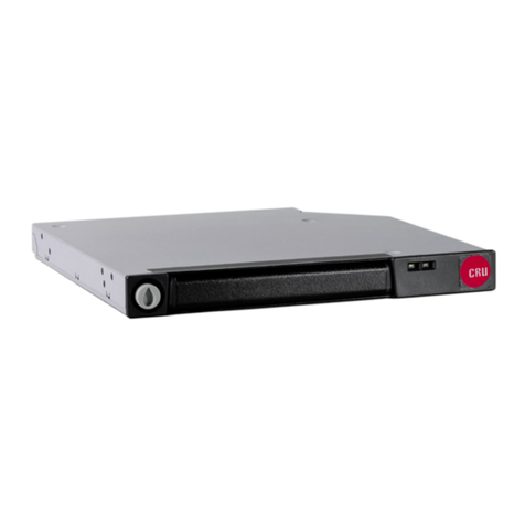
The DataPort22 is a small form factor removable for 2.5” SATA hard drives specifi-
cally developed for the Dell Optiplex™ chassis and other computers with limited
internal space. It can be mounted in any standard 3.5” floppy bay.
11. Replace slim optical drive and top cover.
12. Follow the instructions to install a hard drive into the DataPort 22
carrier.
Installing the DataPort 22 into a Standard Computer Chassis
1. Turn off the computer and disconnect the power cord from the electri-
cal outlet. Wait one minute for any residual energy to dissipate, and
then ensure that you are grounded.
2. Remove the covers from the computer chassis.
3. Locate an available 3.5” drive bay and remove the existing floppy
drive or blank bezel.
If the mounting the DataPort 22 in a larger bay, first install it into
the rails or adapter provided by your computer manufacturer and
remove the corresponding bezel/filler plate.
4. Remove the hard drive carrier from the DataPort 22 frame and set aside.
5. Insert the DataPort 22
into the 3.5” floppy bay
from inside the chassis.
6. Attach an internal
Serial ATA cable to the
host then connect it to
the underside of the
frame.
7. Connect the supplied
SATA to 2-pin JST power
adapter to underside of the frame and to an available SATA power
connector from the power supply.
8. Insert the DataPort 22 into the drive bay and align with the front
bezel of the computer.
Figure 2: SATA to 2-pin JST Power Adapter
Rugged, Reliable, Mobile, SecureTM
1-800-260-9800 www.CRU-DataPort.com
9. Secure to the chassis with mounting screws (not included).
10. Replace the covers on the computer chassis.
11. Follow the instructions to install a hard drive into the Dataport 22 carrier.
Installing a Hard Drive into the DataPort 22 Carrier
Warning! The DataPort 22 frame will only support a DataPort 22 carrier.
Any other carrier will not fit and may cause damage to the unit.
1. Slide the carrier out of the frame.
2. On the rear of the carrier, pull downward on the lower edge to
release the top cover as shown in Figure #.
<figure (#) cover removal>
3. Using the other hand, slide the top cover backwards to remove.
4. Ensure that you are properly grounded and insert a 2.5” Serial ATA
hard drive into the unified data/power connector.
5. Secure the hard drive to the bottom of the carrier using the (4) drive
mounting screws provided.
6. Slide the top cover back on, applying upward pressure on the back of
the cover to snap into place.
Operation
1. Slide the carrier into the frame assembly mounted in the chassis.
2. Insert the key into the lock and turn 90 degrees clockwise to the
“ON” position before powering on the computer.
Powering On/Off
The lock on the DataPort 22 locks the carrier in place while also serving
as an “ON/OFF” switch. Turn the lock 90 degrees clockwise to the “ON”
position before powering up the computer.
For hot-swap capable systems, the computer can be running while the
DataPort 22 is powered on and off.
LED Functions
The DataPort 22 has two status LEDs above the keylock:
Green (Power LED): Indicates that
a drive is present and the DataPort
22 is powered on. (keylock is
engaged)
Amber (Drive Activity LED):
Displays when drive is being ac-
cessed. (Some hard drives do not support
this feature)
Limited Product Warranty
CRU-DataPort (CRU) warrants the DataPort 22 to be free of significant
defects in material and workmanship for a period of five (5) years from
the original date of purchase. CRU’s warranty is nontransferable and is
limited to the original purchaser.
Limitation of Liability
The warranties set forth in this agreement replace all other warran-
ties. CRU expressly disclaims all other warranties, including but not
limited to, the implied warranties of merchantability and fitness for
a particular purpose and non-infringement of third-party rights with
respect to the documentation and hardware. No CRU dealer, agent or
employee is authorized to make any modification, extension, or addition
to this warranty. In no event will CRU or its suppliers be liable for any
costs of procurement of substitute products or services, lost profits,
loss of information or data, computer malfunction, or any other special,
indirect, consequential, or incidental damages arising in any way out of
the sale of, use of, or inability to use any CRU product or service, even
if CRU has been advised of the possibility of such damages. In no case
shall CRU’s liability exceed the actual money paid for the products at is-
sue. CRU reserves the right to make modifications and additions to this
product without notice or taking on additional liability.
Register your product at www.CRU-DataPort.com.
A5-022-0001 Rev 2.0
Figure 4: keylock/LED diagram
Figure 3: DataPort 22 Frame
Other CRU Enclosure manuals

CRU DataPort DP25 SATA 6G User manual

CRU

CRU DataPort DP25 SATA 6G User manual

CRU RTX220-3SJ User manual

CRU

CRU RTX220-3SJ User manual

CRU DataPort 1U User manual

CRU

CRU DataPort 1U User manual

CRU Data Express QX310 User manual

CRU

CRU Data Express QX310 User manual

CRU DataPort 41 User manual

CRU

CRU DataPort 41 User manual

CRU Rhino Jr RJ34S User manual

CRU

CRU Rhino Jr RJ34S User manual

CRU DataPort SecureDock User manual

CRU

CRU DataPort SecureDock User manual

CRU RAX Secure 212-3QR User manual

CRU

CRU RAX Secure 212-3QR User manual

CRU Rhino Jr RJ33S User manual

CRU

CRU Rhino Jr RJ33S User manual

CRU Rhino Jr RJ400 User manual

CRU

CRU Rhino Jr RJ400 User manual

CRU Rhino Jr RJ32T User manual

CRU

CRU Rhino Jr RJ32T User manual

CRU DataPort 2 Bay User manual

CRU

CRU DataPort 2 Bay User manual

CRU Data Express 50 User manual

CRU

CRU Data Express 50 User manual

CRU RTX 1-Bay-3Q User manual

CRU

CRU RTX 1-Bay-3Q User manual

CRU DE100 Ultra 160 User manual

CRU

CRU DE100 Ultra 160 User manual

CRU RAX Secure 212-3QJ User manual

CRU

CRU RAX Secure 212-3QJ User manual

CRU RTX430-3QR User manual

CRU

CRU RTX430-3QR User manual

CRU ToughTech Duo C User manual

CRU

CRU ToughTech Duo C User manual

CRU DataExpress 115 DCmini User manual

CRU

CRU DataExpress 115 DCmini User manual

CRU RTX220-3QR User manual

CRU

CRU RTX220-3QR User manual

CRU RAX 3QJ Series User manual

CRU

CRU RAX 3QJ Series User manual

CRU DataPort 20 User manual

CRU

CRU DataPort 20 User manual

CRU QX310 v2 User manual

CRU

CRU QX310 v2 User manual

CRU MoveDock USB 3.0 User manual

CRU

CRU MoveDock USB 3.0 User manual

Popular Enclosure manuals by other brands

spirit of gamer DEATHMATCH Series manual

spirit of gamer

spirit of gamer DEATHMATCH Series manual

DISCOVER AES RACKMOUNT manual

DISCOVER

DISCOVER AES RACKMOUNT manual

Yeong Yang YY-0221 Technical Instruction

Yeong Yang

Yeong Yang YY-0221 Technical Instruction

Dell PowerVault MD3000 Getting started guide

Dell

Dell PowerVault MD3000 Getting started guide

Bosch HCP 0006 A Quick installation guide

Bosch

Bosch HCP 0006 A Quick installation guide

Kingston Technology DATA EXPRESS DE90 installation manual

Kingston Technology

Kingston Technology DATA EXPRESS DE90 installation manual

Kicker TCVT10 owner's manual

Kicker

Kicker TCVT10 owner's manual

D-Link DSM-G600 - MediaLounge Wireless G Network Storage Enclosure NAS... manual

D-Link

D-Link DSM-G600 - MediaLounge Wireless G Network Storage Enclosure NAS... manual

Panduit PZWRKA installation instructions

Panduit

Panduit PZWRKA installation instructions

Allen-Bradley PowerFlex Active Front End installation instructions

Allen-Bradley

Allen-Bradley PowerFlex Active Front End installation instructions

SINGULARITY COMPUTERS STREAM-S ITX manual

SINGULARITY COMPUTERS

SINGULARITY COMPUTERS STREAM-S ITX manual

Antec Veris Fusion Remote Max Parts Breakdown

Antec

Antec Veris Fusion Remote Max Parts Breakdown

Supermicro SC847E1C Series user manual

Supermicro

Supermicro SC847E1C Series user manual

Belkin RK1000 user manual

Belkin

Belkin RK1000 user manual

Heckler Design WindFall H604 Assembly & installation

Heckler Design

Heckler Design WindFall H604 Assembly & installation

ENERMAX MarbleShell MS30 user manual

ENERMAX

ENERMAX MarbleShell MS30 user manual

Addonics Technologies AD5HPMRXA-E user guide

Addonics Technologies

Addonics Technologies AD5HPMRXA-E user guide

Panduit FCE1U installation instructions

Panduit

Panduit FCE1U installation instructions

manuals.online logo
manuals.online logoBrands
  • About & Mission
  • Contact us
  • Privacy Policy
  • Terms and Conditions

Copyright 2025 Manuals.Online. All Rights Reserved.