Hexagon Veripos LD8 User manual

LD8 INSTALLATION MANUAL
AB-V-MA-00634_RevA
5 September 2019

Introduction
LD8 Installation Manual AB-V-MA-00634_RevA 2
CONTENTS
1. Introduction.............................................................................................................................. 4
1.1 General Information............................................................................................................. 4
1.2 Scope.................................................................................................................................. 4
1.2.1 Preamble........................................................................................................................... 4
1.3 VERIPOS Helpdesk ............................................................................................................ 4
1.4 Terms and Abbreviations .................................................................................................... 5
1.5 Equipment Care.................................................................................................................. 6
1.5.1 Unpacking and Inspection............................................................................................ 6
1.5.2 Safety Warnings........................................................................................................... 6
1.5.3 Installation.................................................................................................................... 6
1.5.4 Maintenance ................................................................................................................ 6
1.5.5 Servicing...................................................................................................................... 6
1.5.6 Fault Diagnosis ............................................................................................................ 6
1.6 Document Conventions....................................................................................................... 7
1.6.1 Typographical Conventions.......................................................................................... 7
1.6.2 Special Notices ............................................................................................................ 7
1.7 Waste Electrical and Electronic Equipment ......................................................................... 8
1.8 Disclaimer........................................................................................................................... 9
2. LD8 System..............................................................................................................................10
2.1 System Overview .............................................................................................................. 10
2.2 Connectors, LEDs and I/O Ports ....................................................................................... 10
2.2.1 Interface Panel........................................................................................................... 10
2.2.2 Connector Types........................................................................................................ 11
2.2.3 LEDs.......................................................................................................................... 12
2.2.4 Serial Ports ................................................................................................................ 12
2.2.5 USB Ports.................................................................................................................. 12
2.2.6 Ethernet ..................................................................................................................... 12
2.2.7 Power......................................................................................................................... 12
3. LD8 Installation .......................................................................................................................13
3.1 LD8 Schematic Example................................................................................................... 13
3.2 Location Guidelines........................................................................................................... 14

Introduction
LD8 Installation Manual AB-V-MA-00634_RevA 3
3.3 Mounting ........................................................................................................................... 14
3.4 Ventilation Requirements .................................................................................................. 15
3.5 Antenna Installation........................................................................................................... 15
3.5.1 GNSS / L-band Antenna Installation Guidelines......................................................... 15
3.5.2 Placement for Heading Antennas............................................................................... 17
3.6 Coaxial Cable Installation.................................................................................................. 19
3.6.1 Maximum Recommended Cable Lengths................................................................... 19
3.6.2 General Cable Guidance............................................................................................ 19
3.7 Antennas........................................................................................................................... 21
3.7.1 Coaxial Cables to Antennas....................................................................................... 21
4. Reference Information ............................................................................................................22
4.1 Technical Specifications.................................................................................................... 22
4.1.1 Dimensions in mm...................................................................................................... 22
4.1.2 Mechanical Specifications.......................................................................................... 22
4.1.3 Compass Safe Distance............................................................................................. 22
4.1.4 Enviromental Specifications ....................................................................................... 22
4.1.5 Safety Considerations................................................................................................ 23
4.1.6 Electrical Specifications.............................................................................................. 23
4.2 Cabling and Connectors.................................................................................................... 24
4.2.1 Power Cable .............................................................................................................. 24
4.2.2 High Density 26 Pin D-TypeConnector......................................................................... 24
4.2.3 I/O Cable.................................................................................................................... 25
5. Contact Information................................................................................................................26
5.1 VERIPOS Helpdesk Details............................................................................................... 26
6. Appendix..................................................................................................................................27
6.1 Summary Specification of Antennas.................................................................................. 27
6.1.1 V460 & V560.............................................................................................................. 27
6.1.2 V460 & V560 Phase Centre Offsets........................................................................... 27
6.2 Summary Specification of Cabling..................................................................................... 29
6.2.1 Times LMR-400 Coaxial cable ................................................................................... 29
6.2.2 Times LMR-240 Coaxial cable ................................................................................... 30

Introduction
LD8 Installation Manual AB-V-MA-00634_RevA 4
1.INTRODUCTION
1.1 GENERAL INFORMATION
It will help to have the following items available when consulting this document:
•VERIPOS LD8 and associated equipment shipped to site.
•The Delivery note provided within the shipment.
•LD8 Operations Manual.
•VERIPOS document Antenna and Coaxial Cable Installation.
•LD8 FAQs and Quick Guides.
1.2 SCOPE
This installation manual provides the information necessary to install the VERIPOS LD8 receiver and covers
these key aspects:
•Antenna installation
•Coaxial cabling
•DC Power requirements
•LD8 mounting
•System interfacing
•Ancillary equipment provided with the LD8
1.2.1 PREAMBLE
Details are provided to assist in locating and connecting equipment ready to be commissioned. Read this
manual in conjunction with the Delivery note provided for your particular installation.
This manual is split into the following sections:
1. Introduction - Details the purpose of the manual, conventions and abbreviations.
2. LD8 System - Describes the LD8 interface panel and provides technical data.
3. LD8 Installation - Covers the installation of the LD8 and provides antenna & cabling guidelines.
4. Reference Information - Provides detailed technical specifications.
5. Contact Information - Contains contact information for the VERIPOS Helpdesk and VERIPOS offices.
1.3 VERIPOS HELPDESK
Throughout this manual, references are made to the VERIPOS Helpdesk. The Helpdesk is a service provided
as first point of contact for all VERIPOS technical enquiries and fault reports. It is manned 24 hours per day,
365 days per year. Full contact details are listed in the Contact Information section.
For support cases VERIPOS recommend that initial contact is made via support@veripos.com, or by raising a
ticket on VOSS https://help.veripos.com. With either method the Helpdesk will be immediately notified and can
begin providing support.
The Helpdesk is trained to aid with common queries and will escalate tickets to regional technical staff for more
complex issues.

Introduction
LD8 Installation Manual AB-V-MA-00634_RevA 5
1.4 TERMS AND ABBREVIATIONS
AC Alternating Current
AltBOC Alternative BOC modulation
APEX VERIPOS high accuracy positioning solution
ARP Antenna Reference Point
BEIDOU Chinese GNSS
BOC Binary Offset Carrier
BNC Bayonet Neill–Concelman
CAN Controller Area Network
C-O Computed Minus Observed
CTS Clear to Send
GALILEO European GNSS
GLONASS Globalnaya Navigatsionnaya Sputnikovaya Sistema - Russian GNSS
GPS Global Positioning System - United States GNSS
GNSS Global Navigation Satellite System
dB Decibel
DC Direct Current
DCE Data Communications Equipment
DGPS Differential GPS
DP Dynamic Positioning
DSUB A electrical connector type
EU European Union
IEC International Electrotechnical Commission
IP Internet Protocol
IPv4 Internet Protocol Version 4
LED Light Emitting Diode
LNA Low Noise Amplifier
L-band Method of transmitting correction data to mobile users
LD8 VERIPOS receiver containing combined L-band and GNSS card
LVCMOS Low Voltage Complementary Metal Oxide Semiconductor
MM Millimetre
PPP Precise Point Positioning
PPS Pulse Per Second
QZSS Japanese GNSS
RF Radio Frequency
RJ45 A physical network interface standard used in telecommunications
RTS Request to Send
SBAS Satellite Based Augmentation System
SMA Sub-Miniature version A
TCP Transmission Control Protocol
TNC Threaded Neill–Concelman
UART Universal Asynchronous Receiver-Transmitter
UI User Interface
UNC Unified National Thread
USB Universal Serial Bus
VAC Voltage Alternating Current
VDC Volts Direct Current
VOSS VERIPOS Online Support System
VSAT Very Small Aperture Terminal
WEEE Waste Electrical and Electronic Equipment

Introduction
LD8 Installation Manual AB-V-MA-00634_RevA 6
1.5 EQUIPMENT CARE
This section summarizes safety guidelines when installing the LD8 unit.
1.5.1 UNPACKING AND INSPECTION
Carefully unpack and inspect the unit. If the equipment appears damaged, then return it using the original
packaging. Responsibility for damage will not be accepted if the approved packaging is not used. Ensure all
the major items and the ancillary equipment are supplied. If any items are found to be missing contact the
system supplier or VERIPOS as soon as possible.
1.5.2 SAFETY WARNINGS
Always observe the following safety precautions:
•Disconnect electrical power from the DC power supply.
•Ensure adequate air circulation to ventilate the unit, especially to the sides to avoid heat build-up.
•Connect only to a power supply with a voltage corresponding to that marked on the unit.
•Always disconnect the LD8 and associated equipment from the power supply when connecting
equipment.
•Never use the equipment in damp or wet conditions.
•Avoid excessive heat, humidity, dust or vibration.
•Do not use the equipment where it may be subjected to dripping or splashing liquids.
•Always use the power connections supplied with the unit.
•Before replacing a fuse, disconnect the equipment from power supply.
1.5.3 INSTALLATION
During installation ensure the following:
•DC power supply is disconnected. The power connection is easily accessed on the unit rear.
•The unit is secured using the holes in the base plate. Position the unit to ensure there is ample
spacing for access to the interface panel and adequate ventilation during normal operation.
•All cables are routed safely to avoid sharp edges, bends and pinches.
•Only the cables specified within this manual are used for interconnection of the equipment.
1.5.4 MAINTENANCE
Clean the unit using a clean dry cloth only. Do not wet the unit or allow the penetration of water. Do not use
solvents to clean the unit.
1.5.5 SERVICING
This unit contains no user-serviceable parts. Please refer all repairs to a qualified service agent or VERIPOS.
1.5.6 FAULT DIAGNOSIS
Follow the guidance in this document to correctly install the LD8. Where the LD8 does not perform as indicated
firstly check all connections before contacting your supplier or VERIPOS for assistance.
Introduction
LD8 Installation Manual AB-V-MA-00634_RevA 7
1.6 DOCUMENT CONVENTIONS
1.6.1 TYPOGRAPHICAL CONVENTIONS
Italic or bold text is used to emphasize certain information. Italic is also used in cross-references to other parts
of the document and to other documents.
Bold text is also used for indicators and touch screen “push-buttons” commands.
“Text within quotes” is used when display screens are mentioned in text.
Monospace text is used for input/output strings to/from the device.
1.6.2 SPECIAL NOTICES
WARNING
A warning indicates the risk of bodily harm or serious damage to the hardware.
CAUTION
A caution indicates the risk of damaging the hardware.
NOTE
A note contains important information to help you make better use of the system.
Introduction
LD8 Installation Manual AB-V-MA-00634_RevA 8
1.7 WASTE ELECTRICAL AND ELECTRONIC EQUIPMENT
The Waste Electrical and Electronic Equipment Directive (hereinafter referred to as the “WEEE directive”)
places an obligation on EU-based manufacturers, distributors, retailers and importers to take-back electronics
products at the end of their useful life. A sister directive, RoHS (Restriction of Hazardous Substances)
complements the WEEE directive by banning the presence of specific hazardous substances in the products at
the design phase. The WEEE directive covers all VERIPOS products imported into the EU as of August 13,
2005. EU-based manufacturers, distributors, retailers and importers are obliged to finance the costs of
recovery from municipal collection points, reuse, and recycling of specified percentages per the requirements
contained in the WEEE Directive.
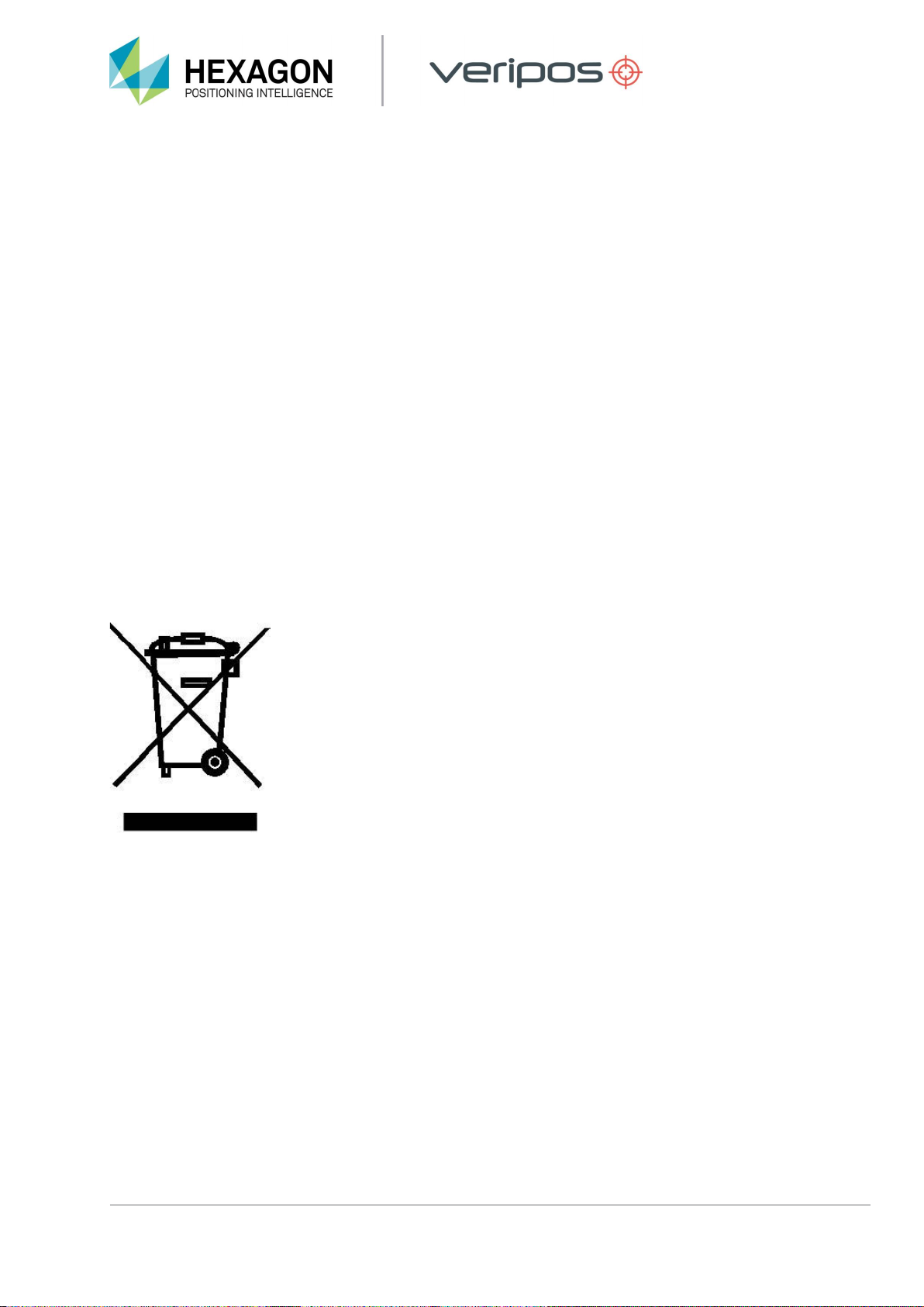
Instructions for disposal of WEEE by users in the European Union
Products which have the undernoted symbol located on either the product itself or its packaging indicates that
the product must not be disposed of with other waste. Instead, it is the user’s responsibility to dispose of the
product by handing it over to a designated collection point for the recycling of WEEE. The symbol shown below
is on the product or on its packaging, which indicates that this product must not be disposed of with other
waste. Instead, it is the user’s responsibility to dispose of their waste equipment by handing it over to a
designated collection point for the recycling of waste electrical and electronic equipment.
The separate collection and recycling of your WEEE at the time of disposal will help to conserve natural
resources and ensure that it is recycled in a manner that protects human health and the environment. For
more information about recycling centres, please contact the local city office, the household waste disposal
service or the product supplier.

Introduction
LD8 Installation Manual AB-V-MA-00634_RevA 9
1.8 DISCLAIMER
VERIPOS Limited (hereinafter referred to as “VERIPOS”) has taken every care in the preparation of the
content of this Manual (“Manual”). This Manual and its contents are provided “as is” without any
representations or warranties, express or implied. VERIPOS makes no representations or warranties in
relation to this Manual and the content provided herein, including but not limited to the safety, suitability,
inaccuracies or typographical errors of this Manual. There are inherent dangers in the use of any software
(including any firmware), and the end user is solely responsible for determining whether the relevant software
provided by VERIPOS and this Manual are compatible with the end user’s equipment and other software
installed on such equipment. End user is also solely responsible for the protection of equipment and the
backup of data.
VERIPOS reserves the right at its sole discretion, but without any obligation, to make amendments or
improvements to, or withdraw or correct any error(s) or omission(s) in any portion of the Manual without notice.
Although VERIPOS makes a reasonable effort to include accurate and up to date information, VERIPOS does
not warrant or represent that this Manual and its contents are current, complete, accurate and/or free from
errors. VERIPOS does not accept any responsibility or liability for the accuracy, content, completeness, legality
or reliability of this Manual and the content provided herein.
VERIPOS accepts no responsibility for any damage or injury to any system, ship or personnel caused by
drawings, instructions or procedures not prepared by VERIPOS.
The software described in this document is furnished under a licence agreement and/or non-disclosure
agreement. The software may be used or copied only in accordance with the terms of such agreement. It is
against the law to copy the software on any medium except as specifically provided for in the license or non-
disclosure agreement.
Copyright © 2019 VERIPOS Limited. All rights reserved.
No part of this Manual and its contents may be reproduced, copied, re-engineered, adapted, redistributed,
published, commercially exploited or transmitted in any form, by any means, electronic or mechanical,
including photocopying or recording, without the express prior written permission of VERIPOS. Applications for
any written permission should be addressed to VERIPOS House, 1B Farburn Terrace, Dyce, Aberdeen, AB21
7DT, United Kingdom.
Unauthorised reproduction, copying, re-engineering, adaptation, redistribution, publication or commercial
exploitation of this Manual or its contents may be subject to civil as well as criminal sanctions under the
applicable laws. VERIPOS will aggressively protect and enforce its intellectual property rights to the fullest
extent, which may include seeking all available remedies in the civil or criminal courts if necessary. Where
reproduction, copying, re-engineering, adaptation, redistribution, publication or commercial exploitation of this
Manual or its contents has been permitted by VERIPOS in accordance with this disclaimer, then no changes in
the Manual or deletion of any kind to the Manual may be made. You acknowledge that you do not acquire any
ownership rights by accessing, viewing or utilising this Manual and agree that you shall not hold itself out to
any third party as having any ownership rights to this Manual.
You further agree to save, indemnify, defend and hold VERIPOS harmless on written demand, from all claims,
losses, damages, costs (including legal costs), expenses and liabilities of any kind and nature, invoked against
VERIPOS by any third party, for or arising out of, any alleged infringement of any proprietary or protected right
arising out of or in connection with your utilisation of this Manual and/or in connection with any representation
made by you to third parties of ownership of any kind with respect to this Manual.
VERIPOS ®is a trademark of VERIPOS Limited and/or its licensors. All other marks used herein are
trademarks of their respective holders.

LD8 System
LD8 Installation Manual AB-V-MA-00634_RevA 10
2.LD8 SYSTEM
This section provides an outline description of the VERIPOS LD8 receiver including details on the different
connectors, LED indicators and also lists information on the internal GNSS receiver.
2.1 SYSTEM OVERVIEW
The LD8 is a high precision system, built into a lightweight, compact and environmentally protected enclosure
and designed to operate reliably in the most demanding of marine environments. Key system features:
•Supports decimetre level multi-constellation positioning with VERIPOS Apex and Ultra PPP correction
services
•Compatible with VERIPOS Quantum software
•EN60945 Marine Certified
•555 channels, all constellation, multi frequency tracking
•Simultaneously track up to 3 VERIPOS correction service satellites
•ALIGN® GNSS heading solution
•Supports RTK operation
•Multiple communication interfaces for easy installation
•WebUI configuration utility
2.2 CONNECTORS, LEDS AND I/O PORTS
TheLD8 cancommunicate withother devices, suchas computers and data loggers using serial, or Ethernet
ports.
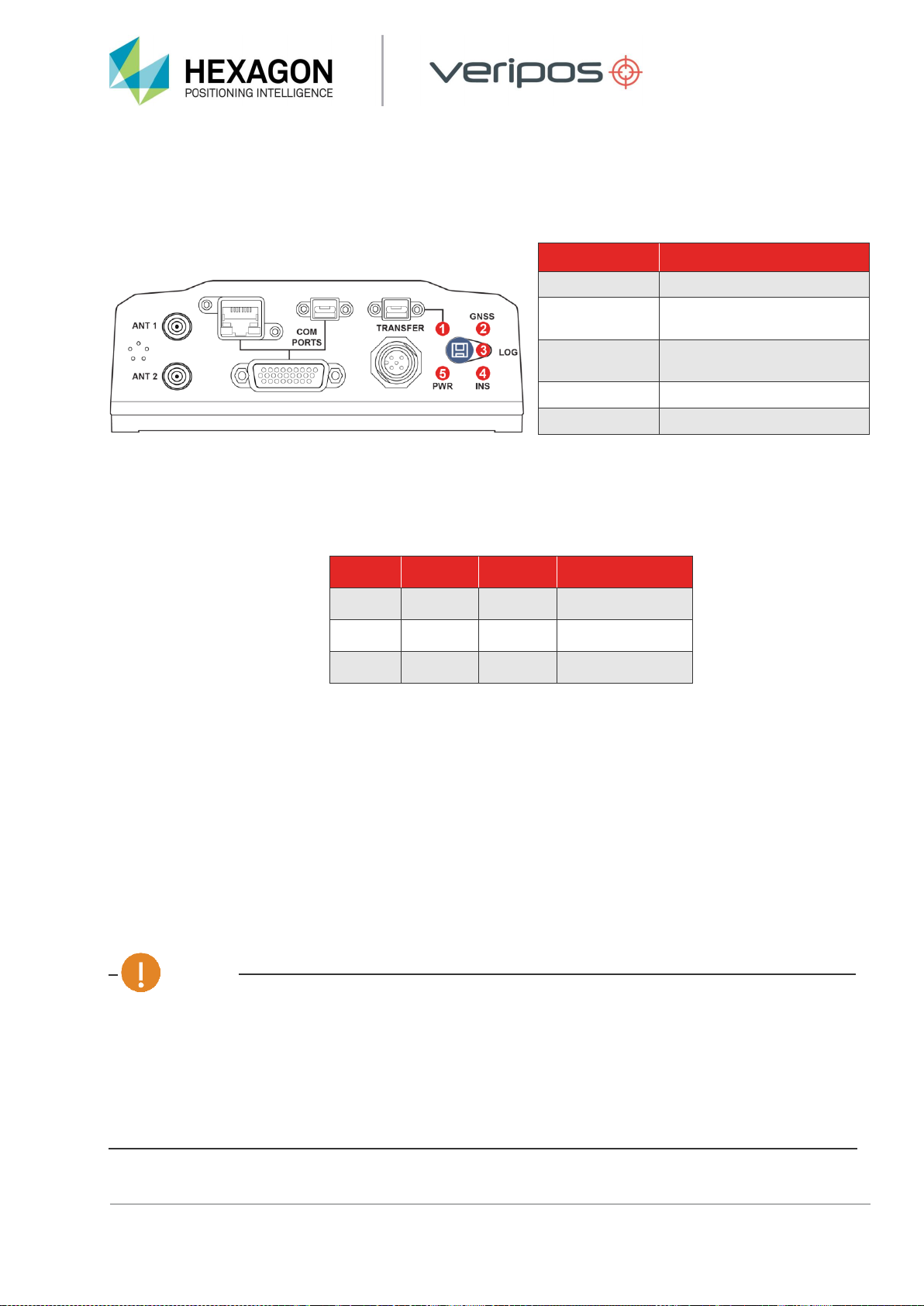
2.2.1 INTERFACE PANEL
The LD8 interface panel has several connectors for interfacing with the unit:
Interface panel of LD8

LD8 System
LD8 Installation Manual AB-V-MA-00634_RevA 11
2.2.2 CONNECTOR TYPES
Connector
Label
Connector
Type
Description
ANT 1
SMA
Primary GNSS connector. Used for the POSITION
reference antenna and the L-band correction signals
ANT 2
SMA
Secondary GNSS antenna ONLY used for GNSS
HEADING systems.
COM
PORTS
RJ45
Ethernet network 100 / 1000
USB Micro
A/B
Currently not supported
High
Density 26
pin D-Type
Provides access to communication signals on the
receiver. This includes:
⚫1Pulse Per Second output (+3.3 volts pulses)
⚫Three bi-directional serialports
⚫COM1 RS-422/RS-232 userselectable
⚫COM2 RS-422/RS-232 userselectable
⚫COM3RS-232
TRANSFER
USB Micro
A/B
Currently not supported
PWR
SAL M12
5Pin
+9 to +36 VDC power input. Multipole connector
LD8 System
LD8 Installation Manual AB-V-MA-00634_RevA 12
2.2.3 LEDS
There arefive LEDindicators used to communicate the receiver status to the user:
LED
Description
1. TRANSFER
Not currently supported
2. GNSS
Indicates the position status of
the receiver.
3. LOG
Indicates the status of logging
to the receiver internal memory
4. INS
Not currently supported
5. PWR
Indicates the power status
2.2.4 SERIAL PORTS
The LD8 has three serial ports: COM1, COM2 and COM3, accessible via the High Density 26 pin D-Type
connector. Refer to the Serial Port Connector section for more details.
Port
RS-232
RS-422
Flow Control
COM1
Yes
Yes
RTS/CTS
COM2
Yes
Yes
No
COM3
Yes
No
No
2.2.5 USB PORTS
The USB ports are currently not supported and should not be used.
2.2.6 ETHERNET
The LD8 has an RJ45 socket that supports 10/100Base-TX Ethernet for interfacing to other IP enabled
systems. TheEthernet port supports IPv4Internet layer.
2.2.7 POWER
The systems power input is required to be 9 to 36 Volts DC, using less than 1 Amp at 12 volts operation. On power
up there is a 1.5 Amp in-rush (for a 12VDC power supply).
CAUTION
If the voltage supplied is below the minimum specification, the receiver will automatically shut down.
If the voltage supplied is above the maximum specification, the receiver may be permanently
damaged, voiding the warranty.
The supply must be capable of providing enough current to operate the LD8, including the initial
inrush transient. The AC / DC power adapter should be protected with a 6 Amp fuse. The DC supply
can be current limited to 6 Amp with an external fuse.
LD8 Installation
LD8 Installation Manual AB-V-MA-00634_RevA 13
3. LD8 INSTALLATION
This section provides guidance on the installation of the LD8 receiver. In the event of difficulty contact your
supplier or VERIPOS (https://help.veripos.com).
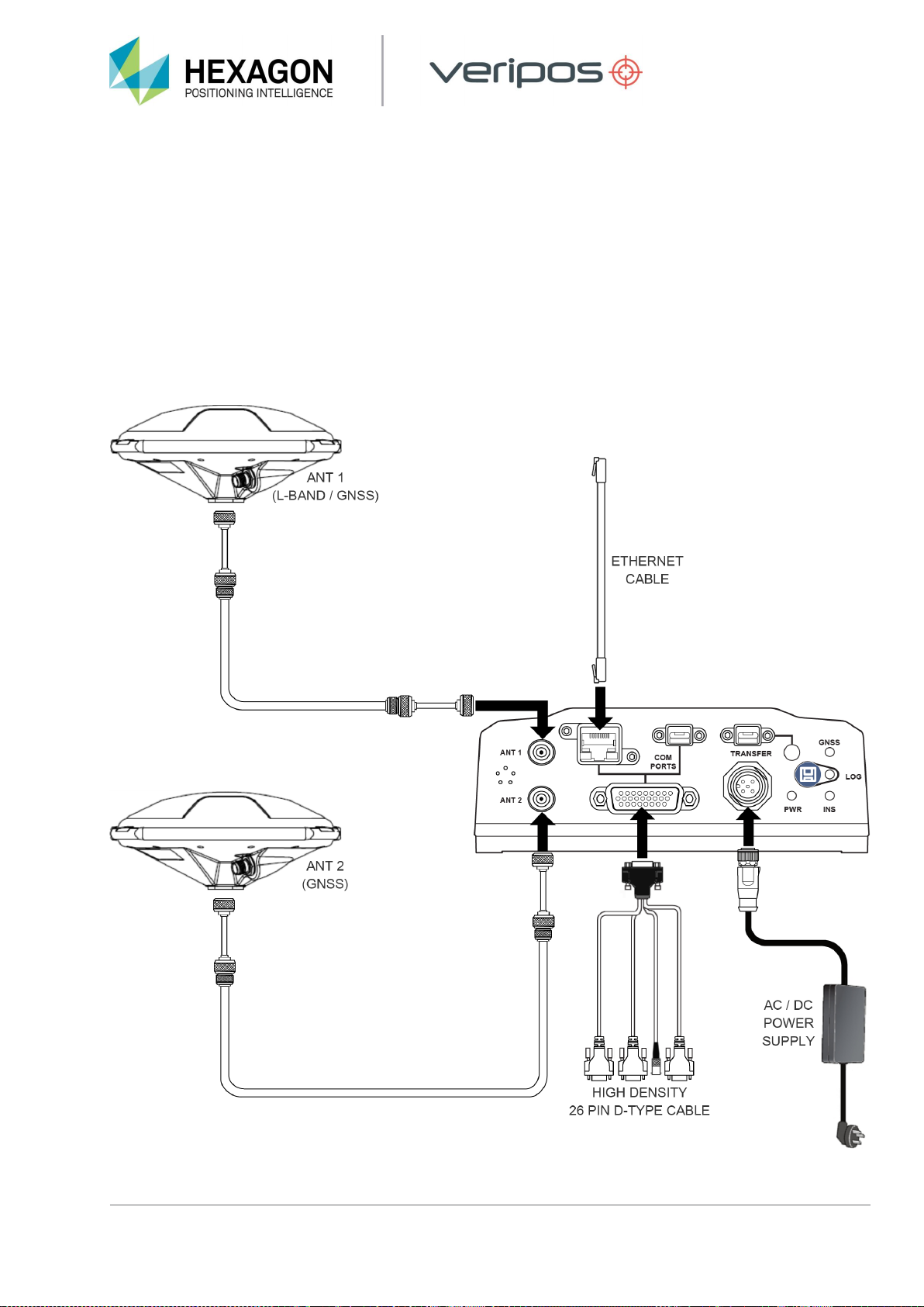
3.1 LD8 SCHEMATIC EXAMPLE
The schematic shown below is one example of an antenna setup arrangement. Please be aware that other
antenna configurations are possible. For long-term installations, always contact VERIPOS to obtain setup
drawings specific to your installation, as these may differ from the example below.
LD8 Installation
LD8 Installation Manual AB-V-MA-00634_RevA 14
3.2 LOCATION GUIDELINES
When choosing installation locations, the following requirements should be taken under consideration:
1. Ensure adequate ventilation for free air flow to the main unit. This is especially important when working in
hot or humid conditions. See section Ventilation Requirements for more details.
2. Locate unit in areas free from excessive dust or smoke.
3. Avoid locations that experience excessive vibration.
4. Avoid exposure to high temperatures.
5. Shield the unit from direct sunlight.
6. Mount the unit securely to prevent movement.
7. Ensure there is easy access to the interface panel.
8. Avoid mounting the receiver in confined spaces. Ensure sufficient slack remains in unit cabling to allow the
rear of the unit to allow easy access.
9. Ensure all bends in coaxial cables are maintained above minimum bend radiuses.
10. Use short tails of flexible coaxial cable (e.g. LMR-240). Ensure sufficient strain relief on the main antenna
coaxial to avoid stress being placed on coaxial connectors.
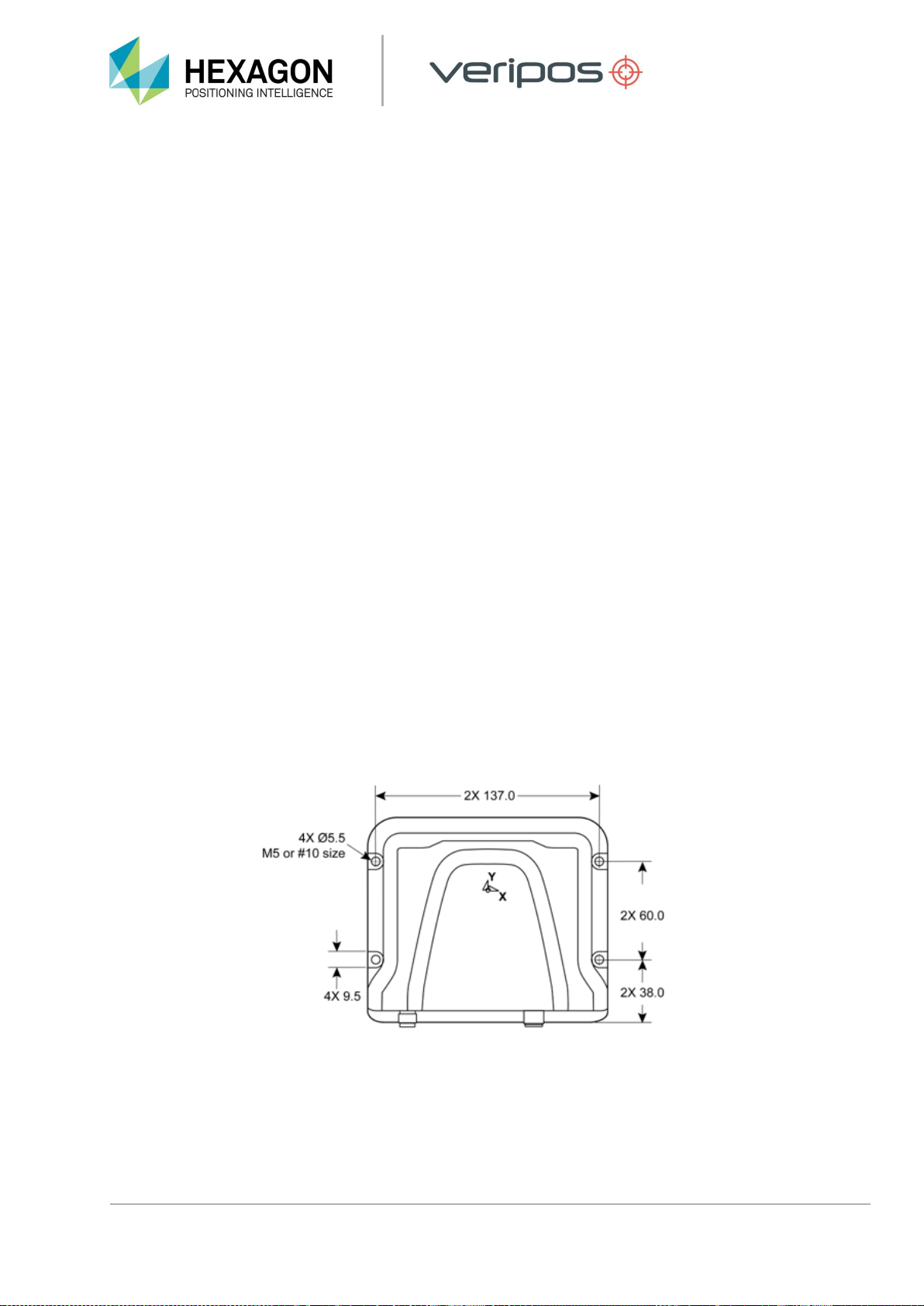
3.3 MOUNTING
Mount the LD8 on a secure, stable surface. The unit can be secured via four M5 mounting holes
(imperial size #10) as shown in the figure below. Take care not toovertightenasthis willresultindamageto
thehousing. Note that thetorqueof the screws should notexceed15inch-lb.

LD8 Installation
LD8 Installation Manual AB-V-MA-00634_RevA 15
3.4 VENTILATION REQUIREMENTS
The LD8 needs 15-25mm clearance all-round to allow an adequate flow of air.
3.5 ANTENNA INSTALLATION
This section provides general guidance on installation of antennas and cabling when installing the LD8
receiver.
It is very important to the on-going performance of your system that a high-quality installation is performed, as
this will ensure optimum performance and reliability.
NOTE
After equipment installation it is recommended that a calibration survey is carried out to compute the heading
offset (also referred to a C-O) and the position offset (Primary GNSS antenna). The position offset and
heading offset should be entered within the navigation or DP software.
3.5.1 GNSS / L-BAND ANTENNA INSTALLATION GUIDELINES
The GNSS antenna receives both multi-constellation and L-band communication satellites (used for VERIPOS
Correction Signals).
This section describes best practice when positioning and installing your GNSS antenna/s.
For more details please refer to VERIPOS document Antenna and Coaxial Cable Installation provided as part
of the installation documentation.
Antennas should be located with a clear 360° view of the sky. The best way to ensure this is to mount the
antenna at the highest possible location. If the GNSS antenna does not have good satellite visibility, there will
be times when system performance is degraded.

LD8 Installation
LD8 Installation Manual AB-V-MA-00634_RevA 16
Examples of good installations –Antennas placed at top of mast with good spacing
During installation observe the following guidelines:
•Offsets to the GNSS antennas must be measured carefully to ensure that no errors are introduced to
the DP, Survey or Navigation systems.
•Care must be taken to ensure that antennas are not installed in the direct path of transmissions from
vessel radar, Inmarsat systems, VSAT systems or high-power HF (whip/wire antennas).
•If the antennas cannot be installed directly at the top of the vessel mast or structure, it is essential that
the mounting point is sufficiently strong for this purpose. The installation must be able to withstand
vibration and wind over a period of many years of operation.
•Stainless steel brackets and mounts are recommended to mitigate the effects of saltwater corrosion.
•A mounting pole can be used with a 5/8"x11 UNC threaded end (standard marine mount). The pole
can be attached by welding, or by using “U” clamps as above. This method allows the antenna to be
mounted without the need for a bracket.
•Ensure that grease (such as copper slip) is applied to the threads when installing the antenna.
•Fit the antenna to the bracket and clamp the bracket to the mounting pole or the mast by using U-
clamps. When mounting the antenna on an extension pole, fit the antenna to the pole first for ease of
handling at height.
•If the threaded pole is already installed up the mast, use a small length of coaxial cable attached to the
N-type connector as a safety lanyard for the antenna.
•Carefully connect the coaxial cable following manufacturers’ guidelines. Form cable below the antenna
into a small loop, approximately 150–220 mm (6 to 8 inch) in diameter.
•Attach the loop to the mounting pole under the antenna to provide strain relief from the cable.
For more detailed guidance please refer to the VERIPOS document Antenna and Coaxial Cable Installation.

LD8 Installation
LD8 Installation Manual AB-V-MA-00634_RevA 17
3.5.2 PLACEMENT FOR HEADING ANTENNAS
Careful consideration for the placement of the primary and secondary antennas is required to maximise the
LD8 GNSS heading accuracy.
3.5.2.1 ANTENNA SEPARATION
The GNSS heading solution accuracy is largely determined by the distance (or baseline) between the primary
and secondary antennas. The larger the baseline, the better the heading precision will be.
The table below details the GNSS heading precision, which relate to the antenna separation baseline.
VERIPOS recommend a minimum baseline of 2m.
Baseline
Static GNSS Heading Precision
1m
0.2°
2m
0.1°
5m
0.04°
10m
0.02°
3.5.2.1 ANTENNA ORIENTATION AND HEIGHT
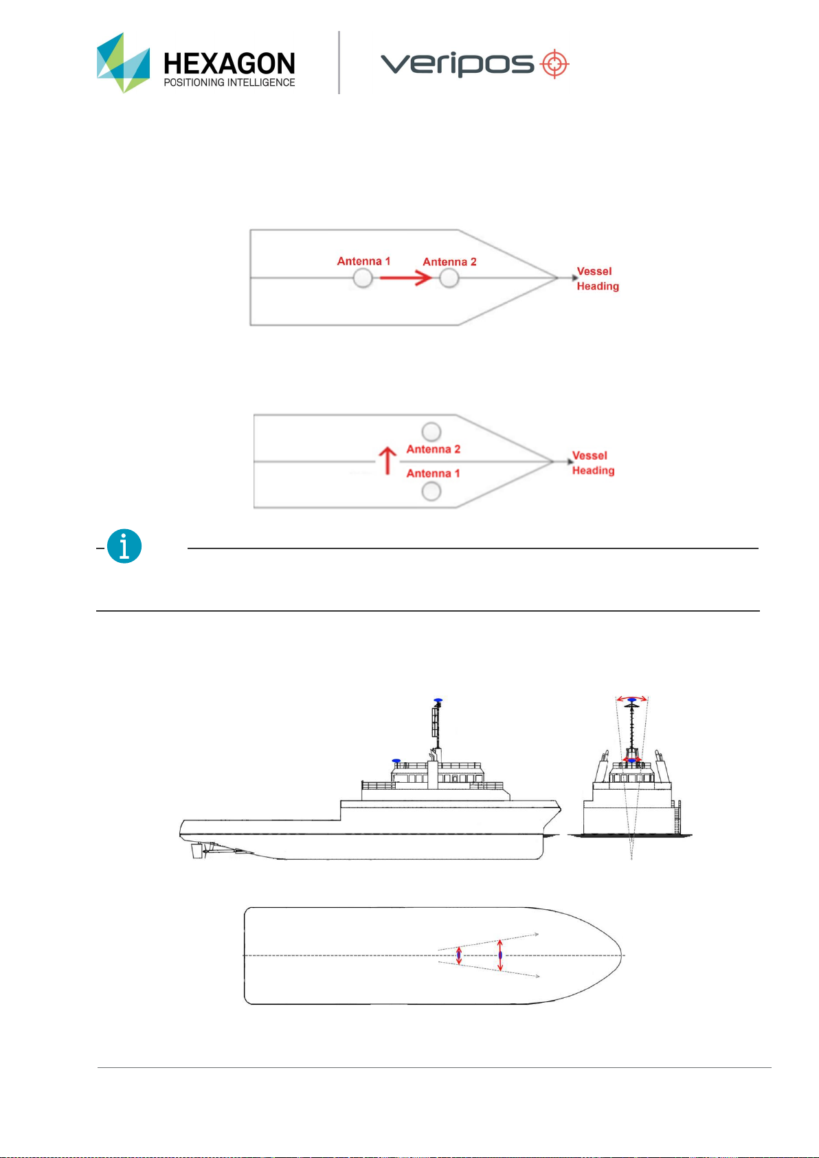
The heading direction is computed from the Antenna 1 to Antenna 2 as illustrated below:
GNSS Heading Solution Direction
LD8 Installation
LD8 Installation Manual AB-V-MA-00634_RevA 18
Assuming the antennas are mounted along the vessel centreline, with Antenna 1 being the furthest
forward antenna, the GNSS heading would closely reflect the vessel heading. In the below example,
a small heading alignment correction would need to be applied in the navigation system software.
In the next example, Antenna 1 and Antenna 2 are installed perpendicular to vessel North with the
Antenna 1 at the Starboard side and Antenna 2 at the Port side. A larger correction offset (C-O)
would be required in the navigation system software to align the GNSS heading to vessel North.
NOTE
The above examples are simplified for illustration purposes. To achieve optimal heading
accuracies a calibration must also be conducted.
Antenna 1 and Antenna 2 should be installed at similar heights to ensure consistent heading. If this
is not done the heading solution will be noisy, due to each antenna being subject to different
amounts of vessel motion (such as vessel roll):
The effect of Vessel motion when antennas (blue) are mounted at different heights

LD8 Installation
LD8 Installation Manual AB-V-MA-00634_RevA 19
3.6 COAXIAL CABLE INSTALLATION
VERIPOS can supply pre-terminated LMR type coaxial cables. The LMR cable type has been found to give the
best overall technical and cost-effective performance. When cables are supplied by VERIPOS they will be
supplied with 2m tails to allow for connection from main cable run to the antenna and the receiver.
3.6.1 MAXIMUM RECOMMENDED CABLE LENGTHS
The various GNSS and differential signals will be attenuated at different rates depending on the signal type
and the quality of the coaxial cable.
The following table shows the maximum recommended cable length for signal types and for three types of
coaxial cable. It is best practice to use lower loss cable, before resorting to the use of inline amplifiers.
L1 GNSS Only
L1/L2 GNSS
L-band
RG213 (M17/163-00001)
40 m / 125 ft
30 m / 110 ft
65 m / 210 ft
LMR-400
70 m / 235 ft
52 m / 175 ft
120 m / 390 ft
LDF4-50
130 m / 425 ft
110 m / 360 ft
210 m / 700 ft
3.6.2 GENERAL CABLE GUIDANCE
The VERIPOS recommended cable for the antenna runs is LMR-400. It is highly recommended that LMR-240
(thinner and more flexible) terminated tails are used at both ends of the LMR-400 cable to ease the attachment
to antennas and receiver RF connectors.
Terminated Tails of LMR-240
When running multiple coaxial cables VERIPOS recommend labelling to ensure cables are attached to the
correct antennas and equipment.
Survey the route of the antenna cabling to ensure:
1. The total length of the cable run does not exceed the supplied cable length for this installation. Contact your
supplier or VERIPOS if this is the case.
2. The cable does not cross or run parallel with any single phase or three phase mains cable (110 VAC, 220
VAC or 440 VAC) or any high-power RF cables leading to transmitting devices such as Inmarsat and VSAT
domes.
3. The cable avoids the proximity to fluorescent lighting and wiring.

LD8 Installation
LD8 Installation Manual AB-V-MA-00634_RevA 20
4. The cable is not placed under tension. A support wire is used where the cable run has to cross a free
space and does not rely solely on cable ties for support.
5. Sufficient space is available in the selected cable entry through the bulk head, for the connectors to pass
through without damage. If the connector cannot pass through the cable entry it may be necessary to cut the
connector off and re-terminate once the cable has been passed through.
6. The cable is not pinched.
7. The route is free from all burrs or sharp edges that could cut the cable jacket over time and lead to water
ingress.
8. All connectors and couplers are completely sealed from the environment with overlapping layers of self-
amalgamating tape and finished with layers of electrical tape or Scotchkote.
9. Stress loops are fitted to prevent excess force on the connectors, in particular on the antenna connectors.
10. The minimum bend radius for the cable is not exceeded.
Typical cable installation in a bridge mast area
Other manuals for Veripos LD8
4
Table of contents
Other Hexagon Receiver manuals


