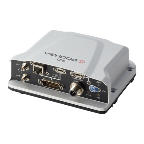
Hexagon VERIPOS LD900 User manual

LD900
Installation and Operations Manual
AB-V-MA-00643_RevA3
26 February 2021

Contents
LD900 Installation and Operations Manual 2
Contents
Contents......................................................................................................................................... 2
1Introduction............................................................................................................................. 4
1.1 General Information....................................................................................................................................................4
1.2 LD900 Receiver..........................................................................................................................................................4
1.3 VERIPOS Support......................................................................................................................................................5
1.4 Activating VERIPOS Correction Services...............................................................................................................5
1.5 Terms and Abbreviations...........................................................................................................................................6
1.6 Document Conventions..............................................................................................................................................8
1.7 LD900 Notices.............................................................................................................................................................9
1.8 Disclaimer..................................................................................................................................................................12
1.9 Equipment Care........................................................................................................................................................13
2Hardware Overview.................................................................................................................14
2.1 System Overview......................................................................................................................................................14
2.2 Hardware Models......................................................................................................................................................14
2.3 Interface and Connectors........................................................................................................................................15
3LD900 Installation....................................................................................................................18
3.1 Schematic Examples................................................................................................................................................18
3.2 Rack Mount Formats................................................................................................................................................21
3.3 LD900 Location Guidelines.....................................................................................................................................24
3.4 LD900 Mounting........................................................................................................................................................24
3.5 Ventilation Requirements........................................................................................................................................25
3.6 Antenna Installation..................................................................................................................................................25
3.7 Cable Installation......................................................................................................................................................28
4Configuration and Operations..................................................................................................30
4.1 Start-Up......................................................................................................................................................................30
4.2 Front Panel Interface................................................................................................................................................30
4.3 Menu & Navigation Basics......................................................................................................................................30
4.4 Status (LD900L Model)............................................................................................................................................31
4.5 Status (LD900 & LD900M Models)........................................................................................................................31
4.6 Configuration.............................................................................................................................................................36
4.7 Receiver.....................................................................................................................................................................52
4.8 Help & Support..........................................................................................................................................................56
5Troubleshooting......................................................................................................................57
5.1 Hardware Issues.......................................................................................................................................................57
5.2 Power Issues.............................................................................................................................................................57
5.3 Activation Issues.......................................................................................................................................................57

Contents
LD900 Installation and Operations Manual 3
5.4 L-band Signal Issues................................................................................................................................................58
5.5 GNSS Signal Issues.................................................................................................................................................58
5.6 Corrections Issues....................................................................................................................................................59
5.7 GNSS Heading Issues.............................................................................................................................................59
5.8 INS Issues..................................................................................................................................................................60
6Reference Information.............................................................................................................61
6.1 Technical Specifications..........................................................................................................................................61
6.2 Cabling and Connectors..........................................................................................................................................63
6.3 Veripos H70 PC Specifications...............................................................................................................................65
6.4 LD900 Output Sentences........................................................................................................................................66
7Contact Information.................................................................................................................80
7.1 VERIPOS HelpdeskDetails....................................................................................................................................80
8Appendix................................................................................................................................81
8.1 Summary Specification of Antennas......................................................................................................................81
8.2 Summary Specification of Cabling.........................................................................................................................83
8.3 Default System Settings..........................................................................................................................................85
8.4 L-band Coverage Map.............................................................................................................................................86

Introduction
LD900 Installation and Operations Manual 4
1 Introduction
1.1 General Information
This documentprovides the information required to install and operate the VERIPOS LD900 receiver.
To assist with the installation and operation it will help to have the following items available when consulting this
document:
•VERIPOS LD900 and associated equipmentshipped to site.
•The Delivery note provided within the shipment.
•VERIPOS document Antenna and CoaxialCable Installation
•LD900 FAQs and QuickGuides, available from https://help.veripos.com.
1.2 LD900Receiver
The LD900 is a scalable integrated positioning sensor, operable as a basic L-band demodulator, or configurable
to meet demanding offshore positioning requirements as a fully integrated mobilepositioning unitwith multi-
frequencyGNSS receiver.Keysystemfeatures:
•Supports decimetre level multi-constellation positioning with VERIPOSApex and Ultra PPP solution
services
•Compatible with VERIPOS Quantum software
•EN60945 Marine Certified
•555 channels, multi-constellation, multi-frequency tracking
•Simultaneously track up to three L-band correction service satellites
•Features advanced signal filtering to mitigate the effects of interference
•Supports RTK operations
•Multiple communication interfacesfor easy installation
•Optional ALIGN® GNSS heading solution
•Optional SPAN® INS solution
•Optional MSKBeacon receive corrections from IALAmarine radio beacon network
•Optional UHF receiver for reception of corrections
•Optional 7 Portexpansion unit
•19 Inch Rack Mount options(for single ordual LD900 systems)
1.2.1 Preamble
The purpose of thismanualis to provide the information necessaryto install and operatethe VERIPOSLD900.
Read this manual in conjunction with the Deliverynote provided for yourinstallation.
This manual is split into the following sections:
1. Introduction - Details the purpose of the manual, conventionsand abbreviations.
2. Hardware Overview - Describesthe LD900interface panel andprovidestechnical data.
3. LD900 Installation - Covers the installation of the LD900 and providesantenna & cabling guidelines.
4. Configuration and Operations - Details system configuration and operationsvia the MMI.
5. Troubleshooting - Provides steps on howto rectify systemissues which a usermay encounter.
6. Reference Information -Providesdetailed technicalspecifications.
7. Contact Information - Containscontactinformation for the VERIPOSHelpdeskand VERIPOSoffices.
8. Appendix -Providesadditional supplementarymaterial.

Introduction
LD900 Installation and Operations Manual 5
1.3 VERIPOS Support
Throughout this manual, referencesare made to the VERIPOS Helpdesk.The Helpdeskis a service provided
as the first pointof contact forall VERIPOStechnical support and faultreports.It is manned24hoursa day,365
days per year. Full contact details are listed in the ContactInformation section.
Contact information for the VERIPOSHelpdesk can also be found onthe LD900 product label located on the
top of the unit or from the MMI Help &Support page.
For support cases, initialcontact should be made via support@veripos.com, or by raising a ticket
(https://help.veripos.com). With either method, the Helpdesk will be immediately notified and can begin
providing support.
The Helpdesk will provide initialsupport; however, tickets maybe escalated to regionalon-call engineersto
provide more in-depth technicalsupport if required.
To aid support,upon firstcontactit would be helpful if the following could be provided:
•Details of the issue or question
•Vessel name
•Companyname
•Telephone number
•Unit UserCode
•VERIPOS hardware type
•VERIPOS software type
•Operating area
•Is this issue holding up operations?
•Any otherrelevantinformation
1.4 Activating VERIPOS Correction Services
Correction services for the LD900 are provided on a subscription basisby VERIPOS.
To activate VERIPOSservices the user must firstsend a service activation request (containing the unit user
code, vessel name, SALnumber and services required) to the VERIPOSHelpdesk. Once processed, the
activation will then be sent via L-band satellite to the unit. The unit will start using VERIPOSservices upon
activation.
When not required, some service agreements mayallow for service deactivation.
NOTE
To use VERIPOS services a contract between the users’ company and VERIPOS must be in place. VERIPOS
refers to thisasa Service Access License (SAL).
To avoid delays users should record and provide theSALnumber associated withthe VERIPOS
equipment.
The Helpdesk are unable to activate any equipment unlessan active SAL exists.

Introduction
LD900 Installation and Operations Manual 6
1.5 Terms and Abbreviations
AC Alternating Current
APEX VERIPOS high accuracypositioning solution
ARP Antenna Reference Point
AWG American Wire Gauge
BEIDOU Chinese commissioned GNSS
BNC A bayonettype of RF coaxial connector
C-O Computed MinusObserved
cm Centimetre
dB Decibel
dBuV Decibel (microVolts)
DC Direct Current
DGNSS Differential GNSS
DGPS Differential GPS
DHCP Dynamic Host Configuration Protocol
DOP Dilution of Precision
DP Dynamic Positioning
DQI Differential QualityIndicator
EN European standard
EU European Union
FCC Federal CommunicationsCommission
GALILEO European commissioned GNSS
GLONASS GLObal NAvigation Satellite System - Russian commissioned GNSS
GNSS Global Navigation Satellite System
GPS Global Positioning System - United Statescommissioned GNSS
HDOP Horizontal Dilution of Precision
HDR High Dynamic Range
Hz Hertz
ID Identification
IEC International Electrotechnical Commission
IMU Integrated Mobile Unit
INS Inertial Navigation System
IP Internet Protocol
IPv4 Internet Protocol Version 4
kg Kilogram
kHz Kilohertz
lb Pound (unit of measuringweight)
LAN Local Area Network
L-band Signal transmitted to carrycorrection data to mobile users
LED Light Emitting Diode
LNA Low Noise Amplifier
MF Third party broadcasting service also referred to as 'MF' or 'Beacon'
MHz Megahertz
MM Millimetre
MMI Man Machine Interface
NM N-Type (male)coaxial connector
NMEA National Marine Electronics Association
NTRIP Networked Transport of RTCM via InternetProtocol
Ohm Unit of electrical resistance
PDOP Positional Dilution of Precision
PPP Precise Point Positioning
PPS Pulse Per Second
PRN Pseudo RandomNoise
PWR Power
QZSS Quasi-Zenith Satellite System - Japanese commissioned GNSS

Introduction
LD900 Installation and Operations Manual 7
RF Radio Frequency
RJ45 A physical networkinterface standard used in telecommunications
RTCM Radio Technical Commission for Maritime Services
RTK Real-time Kinematic
s Seconds
SAL Serial Access License
SAL M12 Sensor Actor Line
SBAS Satellite Based Augmentation System
Standard VERIPOS Single frequencyDGPSsystem
SV Space Vehicle
TCP Transmission Control Protocol
TNC A threaded type of RF coaxial connector
TNCM A threaded type of RF coaxial connector(male)
UART Universal Asynchronous Receiver-Transmitter
UI User Interface
Ultra VERIPOS high accuracy positioning solution
UNC Unified National Coarse Thread
USB Universal Serial Bus
UTC Coordinated Universal Time
VAC Voltage Alternating Current
VDC Volts Direct Current
VDOP Vertical Dilution of Precision
VOSS VERIPOS Online Support System
VSAT Very Small Aperture Terminal
WEEE Waste Electrical and Electronic Equipment
Wi-Fi Wireless-Fidelity,a term whichreferenceswireless radio frequency networking

Introduction
LD900 Installation and Operations Manual 8
1.6 DocumentConventions
1.6.1 Typographical Conventions
Italic or boldtext is used to emphasize certain information. Italic is also used in cross-references to other parts
of the document and to other documents.
Bold text is also used for indicators and touch screen “push-buttons” commands.
Blue text is used for hyperlinking to other sectionswithin this document or to external documents orwebsites.
Bold italic text is used when displayscreensare mentioned in text.
Monospace text is used for input/output strings to/from thedevice.
1.6.2 Special Notices
WARNING
A warning indicates the risk of bodily harm or serious damage to the hardware.
CAUTION
A caution indicates the risk of damagingthe hardware or adversely impactingthe
operation of the system.
NOTE
A note containsimportant information to help you make better use of the system.

Introduction
LD900 Installation and Operations Manual 9
1.7 LD900Notices
The following notices apply to the LD900:
1.7.1 Waste Electrical and Electronic Equipment
The Waste Electrical and Electronic Equipment Directive (hereinafter referred to as the “WEEE directive”)
places an obligationon EU-based manufacturers, distributors, retailers and importers to take-back electronics
products at the end of their useful life.A sister directive,RoHS(Restriction ofHazardous Substances)
complements the WEEEdirectiveby banning the presence of specific hazardous substancesin the products at
the design phase. The WEEEdirective covers all VERIPOSproducts imported into the EU as of August13,
2005. EU-based manufacturers,distributors, retailers and importersare obliged to finance the costs ofrecovery
from municipal collection points, reuse,and recycling of specified percentages per the requirements contained
in the WEEE Directive.
Instructions for disposal of WEEE by users in the EuropeanUnion
Products which have the undernoted symbol located on either the product itself or its packaging indicatesthat
the product must not be disposed of with other waste. Instead, it is the user’s responsibility to dispose of the
product byhanding it over to a designated collection point for the recycling of WEEE.The symbolshown below
is on the productor on its packaging, which indicates that this product must notbe disposed of with other waste.
Instead, it is the user’s responsibility to dispose of their waste equipment by handing it over to a designated
collection point for the recycling of waste electrical and electronic equipment.
The separate collection and recycling of yourWEEEat the time of disposalwill help to conserve natural
resources and ensure that it is recycled in a mannerthat protectshuman health and the environment. For more
information about recycling centres, please contactthe localcity office, the household waste disposal service or
the product supplier.

Introduction
LD900 Installation and Operations Manual 10
1.7.2 FCC
This device complieswith part 15 of the FCC Rules. Operation is subject to the following two conditions: (1) this
device may notcause harmful interference,and (2) this device must accept any interference received, including
interference thatmaycause undesired operation.
LD900 has been tested and found to comply with the radiated and conducted emission limits for a Class B
digital device. The ClassB limits are designed to provide reasonable protection against harmful interferencein a
residential installation.
The equipment listed generates, usesand can radiate radio frequency energyand,if not installed and used in
accordance with the instructions,maycause harmfulinterference to radio communications.However, there is
no guarantee that interferencewill notoccur in a particular installation. If this equipment doescause harmful
interference to radio or television reception, which can be determined by turning the equipmentoff and on, the
user is encouraged to try to correctthe interferenceby oneor more of the following measures:
•Re-orient or relocate the LD900
•Increase the separation between the equipment and the LD900
•Connect the equipmentto an outlet on a circuitdifferentfrom that to which the LD900 is connected
•Consult VERIPOSforhelp
CAUTION
To maintain compliance with the limits of a Class B digital device,you must use shielded interface
cables
WARNING
The LD900 has been authorised for use in Mobile applications. At least 20 cm (8 inches) of separation
between the LD900and the User mustbe maintainedduring normal operation.
WARNING
Changes or modificationsto this equipment, not expressly approvedby VERIPOS couldvoid the
user’s authority to operate this equipment.
1.7.2.1 Wi-Fi
LD900 containsa Wi-Fi radio with the following approval:
•FCCID: Z64-WL18SBMOD (USA)

Introduction
LD900 Installation and Operations Manual 11
1.7.3 European Union
1.7.3.1 Radio Equipment Directive
VERIPOS declaresthat theLD900 including its Wi-Fi transceiver isin compliance with Directive 2014/53/EU
(Radio Equipment).
Radio Information:
Description of Service:Wi-Fi (802.11b/g/n)
Operational Frequency: 2412 MHzto 2462 MHz
Modulation: OFDM
Rated Power: 16.38dBm
The full text of the EU Declaration of Conformity maybe obtained fromVERIPOSupon request.
1.7.3.2 ROHS
The LD900 is in conformity with Directive2011/65/EU of the European Parliament and of the council of 8 June
2011 on the restriction of the use of certain hazardoussubstances in electrical and electronic equipment.
1.7.3.3 Reach
The LD900 is compliant with Regulation (EC) No. 1907/2006 of the European Parliament and the Council of 18
December 2006 concerning the Registration,Evaluation, Authorization and Restriction of Chemicals (REACH).
The candidate list of Substances of Very High Concern (SVHC) published by the European Chemical Agency
(ECHA) is available at: https://echa.europa.eu-/candidate-list-table.

Introduction
LD900 Installation and Operations Manual 12
1.8 Disclaimer
VERIPOS Limited (hereinafter referred to as “VERIPOS”) has taken every care in the preparation of the content of this
Manual (“Manual”). This Manual and its contents are provided “as is” without any representations or warranties, express
orimplied.VERIPOSmakesnorepresentationsorwarrantiesinrelationto thisManualandthecontentprovided herein,
including butnotlimited to the safety,suitability,inaccuraciesortypographical errorsof thisManual.Thereare inherent
dangers in the use of any software (including any firmware), and the end user is solely responsible for determining
whether the relevant software providedby VERIPOS and this Manual are compatible with the end user’s equipment
and othersoftware installedonsuch equipment.End userisalso solelyresponsibleforthe protection of equipmentand
the backupof data.
VERIPOS reservestherightat its sole discretion,butwithoutanyobligation,tomakeamendmentsorimprovementsto,
orwithdraworcorrectanyerror(s)oromission(s)inanyportionoftheManualwithoutnotice.Although VERIPOSmakes
a reasonableeffort to include accurate and up to date information, VERIPOS does not warrant or represent that this
Manual and its contents are current, complete, accurate and/or free from errors. VERIPOS does not accept any
responsibility or liability for the accuracy, content,completeness, legality or reliability of this Manual and the content
providedherein.
If you have any questions or comments about this Manual or our Privacy Policy, please contact us at:
support@veripos.com.
The LD900hardwareandassociated software issubjectto VERIPOS Termsand ConditionsRelatingtothe Provision
of VERIPOS Services.
Thesoftwaredescribedinthisdocumentisfurnishedunderalicenceagreementand/ornon-disclosure agreement.The
softwaremaybe usedor copiedonlyinaccordancewith thetermsof such agreement.Itis againstthe lawto copy the
softwareon anymedium exceptasspecificallyprovided forinthelicense ornon-disclosureagreement.
Copyright©2020 VERIPOS Limited.All rightsreserved.
No part of this Manual and its contents may be reproduced, copied, re-engineered, adapted, redistributed, published,
commerciallyexploitedortransmitted inany form,byany means,electronicor mechanical,includingphotocopyingor
recording,withoutthe expressprior writtenpermission of VERIPOS. Applicationsforanywritten permissionshouldbe
addressedtoVERIPOS House,1B FarburnTerrace,Dyce, Aberdeen,AB21 7DT,United Kingdom.
Unauthorised reproduction, copying, re-engineering, adaptation, redistribution, publication or commercial exploitation
of this Manualorits contentsmaybe subjectto civilas wellas criminalsanctionsundertheapplicablelaws.VERIPOS
will aggressively protect and enforce its intellectualproperty rights to the fullest extent,which may include seekingall
available remediesin the civilorcriminalcourtsif necessary.Wherereproduction,copying,re-engineering,adaptation,
redistribution,publication orcommercialexploitationof thisManualorits contents has beenpermittedby VERIPOS in
accordance with this disclaimer, then no changes in the Manual or deletion of any kind to the Manual may be made.
You acknowledgethatyou do notacquire anyownershiprightsbyaccessing,viewingorutilisingthisManual andagree
that you shallnotholditself outto anythirdparty as havinganyownershiprightstothisManual.
You furtheragree to save, indemnify,defend andhold VERIPOSharmlessonwritten demand,fromall claims,losses,
damages, costs (includinglegalcosts), expenses and liabilities of any kind andnature, invoked against VERIPOS by
any third party, for or arising out of, any alleged infringement of any proprietary or protected right arising out of or in
connection withyourutilisationof thisManualand/orinconnectionwithanyrepresentation made byyoutothird parties
of ownership of anykindwithrespectto this Manual.
VERIPOS ® is a trademarkof VERIPOS Limited and/oritslicensors.All othermarksusedherein are trademarksof their
respective holders. All other marks used herein are trademarks of their respective holders. Veripos Limited is part of
the Hexagon Autonomyand Positioningdivision of companiesof Hexagon AB.

Introduction
LD900 Installation and Operations Manual 13
1.9 EquipmentCare
1.9.1 Unpacking and Inspection
Carefully unpackand inspect theunit.If theequipment appearsdamaged,contactVERIPOSforfurtheradvice
ensuring to retain the original packaging. Responsibility for damage will not be accepted if approved packaging
is not used. Ensure all the major items and the ancillary equipment are supplied. If any items are found to be
missing, contact theVERIPOS or systemsupplier as soon aspossible.
1.9.2 Safety Warnings
Always observe the following safety precautions:
•Ensure adequate air circulation to ventilate the unit, especially to the sidesto avoid heat build-up.
•Connect onlyto a power supply with a voltage within the range 12V to 24VDC.
•Always disconnectthe LD900fromthe power source when connecting equipment.
•Never use the equipment in damp orwet conditions.
•Avoid excessive heat, humidity, dust orvibration.
•Do not usewhere the equipment maybe subjected to dripping or splashing liquids.
•Always use the power connections supplied with the unit.
•Before replacing a fuse,disconnect the equipment from the power source.
1.9.3 Installation
During installation ensure the following:
•DC power supplyis disconnected.The power connection iseasily accessed on the unit rear.
•The unit is secured using the holes in the base plate. Position the unit to ensure there is ample spacing
for accessto the front interface panel and adequate ventilation during normal operation.
•All cablesare routed safely to avoid sharp edges, excessive bendsand pinches.
•Only the cables specified within thismanual are used for interconnection of the equipment.
•Ensure equipment is connected to the ships ground.
1.9.4 Maintenance
Clean the unit using a clean drycloth only. Do notwet the unit orallow the penetration of water.Do not use
solvents to clean the unit.
1.9.5 Servicing
This unit contains no user-serviceable parts. Please refer all repairs to a qualified service agentor VERIPOS.
1.9.6 Fault Diagnosis
Follow the guidance in this document to correctly install the LD900. Where the LD900 does not perform as
indicated firstly check all connections before contacting your supplier or VERIPOS for assistance.

Hardware Overview
LD900 Installation and Operations Manual 14
2 Hardware Overview
This section providesan overview ofthe VERIPOSLD900 receiver and details the physical characteristics of
the systemand the differentmodels.
2.1 SystemOverview
The LD900 is a high precision system, builtinto a rugged enclosure and designed to operate reliablyin the most
demanding of marine environments. The LD900 is available in three separate models and can be upgraded as
required to provide any VERIPOSpositioning solutions.Keymodel-dependentsystemfeaturesinclude:
•Multi-channel L-band reception supporting all VERIPOS correction services
•Multi-constellation GNSSsystemwith a quad-frequency capability
•Dual antenna inputs for heading
•Multiple RS232 / RS422 ports
•Dual Ethernet ports
•Front panel display UI
•Integrated data logging
•Optional INS
2.2 HardwareModels
The product label on top of the LD900 will indicate the model, with the system available in three models:
Model
Receiver Modules
LD900L
L-band
LD900
L-band, GNSS
LD900M
L-band, GNSS& MF
Both the LD900 and LD900Mmodels are capableof GPS, GLONASS, BeiDou, Galileo and QZSSmulti-
constellationtracking.The constellationsused in the calculated solutions willdepend on the useof the
appropriate activated VERIPOS services.

Hardware Overview
LD900 Installation and Operations Manual 15
2.3 Interface and Connectors
The LD900 features a 3.5” colour MMI with keys to navigate the UI, allowing for user configuration and status
monitoring.
2.3.1 Front Panel Interface
The LD900 frontpanelprovidesa displayUI, controls and USB 2.0 port forsystemupdatesand data archiving:
2.3.2 Rear Panel Connectors
The LD900 rear panel has several RF and data connectors for interfacing with the unit:
Label
Connector
Description
GNSS1
TNC
Primary GNSS connector. Used to generatethe receiver position and
default means ofL-band signal reception.
GNSS2
TNC
Secondary GNSS antenna. Only used for GNSS heading systems to
generate a heading in relationto theGNSS1 antenna.
LBAND
TNC
L-band antennaconnector(configuration dependent)
BEACON
TNC
MF antennaconnector
PPS
BNC
1PPS output
COM1, COM2, COM3
DB9
RS-422/RS-232
AUX
DB15
For connection to UHF module.
LAN1
RJ45
Ethernet network 10/100Mbps for data output.
LAN2
RJ45
Ethernet network 10/100Mbps for connection to Quantum
PWR
SAL M12 4 Pin
12 to 24 VDCpower input

Hardware Overview
LD900 Installation and Operations Manual 16
2.3.2.1 Serial Ports
The LD900 has three serial ports: COM1, COM2 and COM3, accessible via 9 pin D-Type connectorsand a 15-
pin D-Type AUXserial port. Refer to the Cabling and Connectors section for more details.
Port
RS-232
RS-422
Galvanically
Isolated
Flow
Control
COM1
Yes
Yes
Yes
No
COM2
Yes
Yes
Yes
No
COM3
Yes
Yes
Yes
No
2.3.2.2 1PPS Output
LD900 and LD900M models are capable of outputting of 1PPS(one pulse per second) signal,synced to
GPS time, which can be used by external equipmentfor accurate time synchronisation. The PPS
voltage with no load is 8V.
2.3.2.3 Ethernet
The LD900 has two RJ45sockets thatsupport Ethernet(10Base-T/100Base-TX) forconfiguration and interfacing
to vesseland surveysystems. BothEthernetportssupportIPv4Internetlayerand TCP/IPtransport.
LAN1 of the LD900 is used for data communications and is shipped with a factory defaultIP address of
192.168.2.91. Connecting systems should be configured to use the same IP subnet. If theLD900 needs to be
configured to join an existing TCP/IP network, the required stepscan be found in sectionReceiver> Network.
LAN2 of the LD900 is available for connecting to Quantumand is shipped with a factory default IP address of
192.168.2.92.
2.3.2.4 Wi-Fi
The LD900has aWireless AccessPointthatisdisabledbydefault but can be enabled via the front panel. This is
intended for use with potential future developments.
2.3.2.5 USB Port
The USB 2.0 port is used for software and firmware updates and exporting logged data.
2.3.2.6 Power
The systems power input isrequired to be 12to 24Vwhenconnecting to a DCpowersource and 110-240Volts
when using the approved AC/DC power supply as provided by VERIPOS:

Hardware Overview
LD900 Installation and Operations Manual 17
CAUTION
If the voltage supplied is below the minimumspecification,the receiver will automatically shut down.
If the voltage supplied is abovethe maximum specification, the receiver may be permanently damaged
and void the warranty.
The supply mustbe capable of providing enough current to operate the LD900.
WARNING
To ensure safety, only limited power sourceAC/DCadapters supplied by VERIPOSshould be used
with the product.
The AC/DC adapter has been tested and approved by VERIPOSand the DC supply cable incorporates
a 10A fuse to protect the unit.
2.3.2.7 Grounding
A chassisgrounding point is provided in the form ofan M4 stud.Connectthisto the ships ground with a
minimum gauge 24AWG wire:

LD900 Installation
LD900 Installation and Operations Manual 18
3 LD900 Installation
This section providesguidance on the installation of the LD900 receiver. In the event of difficulty, contactyour
supplierorVERIPOS (support@veripos.com).
CAUTION
The personnel responsible for installing the LD900 systemmust be properly trainedand competent to
install electronic equipment.
WARNING
No user-accessible parts. Disconnect the GNSS antenna(s) prior to servicing the LD900. Only trained
personnel are permitted to install/service the LD900 and antennas.
3.1 SchematicExamples
The schematics shown below represent three examplesof antenna setup arrangement. Please be aware that
otherantenna configurationsare possible. Forlong-terminstallations, alwayscontactVERIPOSto obtainsetup
drawings specific to yourinstallation, as these may differfromthe examplesbelow:
3.1.1 L-band Demodulator Installation (LD900L Model)

LD900 Installation
LD900 Installation and Operations Manual 19
3.1.2 Survey Installation (LD900 Model)
Heading Option
Independent L-bandOption

LD900 Installation
LD900 Installation and Operations Manual 20
3.1.3 DP Installation (LD900M Model)
Heading Option
Other manuals for VERIPOS LD900
2
This manual suits for next models
2
Table of contents
Other Hexagon Receiver manuals