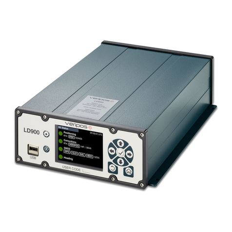
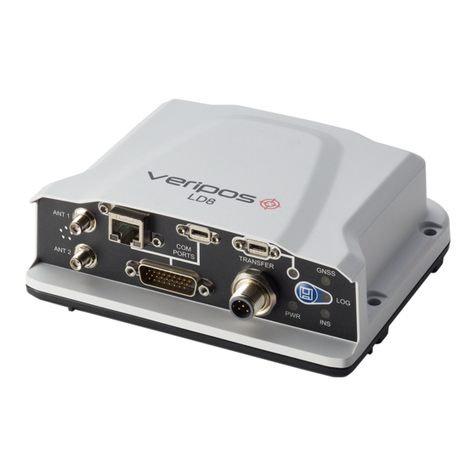
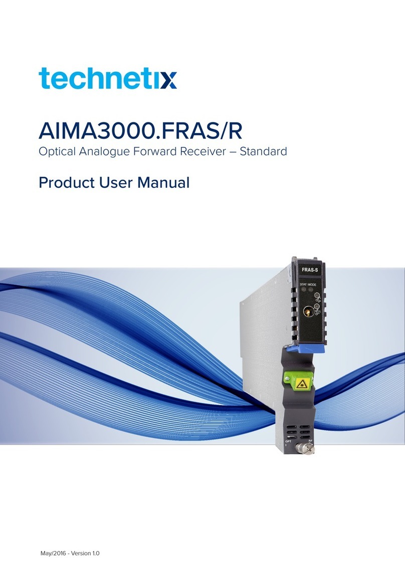
Hexagon Veripos LD8 User manual

LD8
Operations Manual
AB-V-MA-00635_RevA6
14 June 2021

Contents
LD8 Operations Manual AB-V-MA-00635_RevA6 2
Contents
1Introduction............................................................................................................................. 3
1.1 LD8 Receiver...............................................................................................................................................................3
1.2 Scope...........................................................................................................................................................................3
1.3 System Requirements................................................................................................................................................3
1.4 VERIPOS Helpdesk...................................................................................................................................................3
1.5 Enabling the LD8 for VERIPOS services................................................................................................................4
1.6 Terms and Abbreviations...........................................................................................................................................5
1.7 Document Conventions..............................................................................................................................................6
1.8 Waste Electrical and Electronic Equipment............................................................................................................7
1.9 Disclaimer....................................................................................................................................................................8
2Hardware Overview.................................................................................................................. 9
2.1 Overview and Description..........................................................................................................................................9
2.2 LEDs.............................................................................................................................................................................9
2.3 Interface Panel Connections...................................................................................................................................11
3Ethernet and WebUI Connection...............................................................................................12
3.1 Ethernet......................................................................................................................................................................12
3.2 WebUI Connection...................................................................................................................................................12
4Configuration and Operation....................................................................................................13
4.1 WebUI Status............................................................................................................................................................13
4.2 L-band Configuration................................................................................................................................................15
4.3 Activation and Deactivation of VERIPOS Services..............................................................................................18
4.4 Calculation Configuration........................................................................................................................................19
4.5 Ethernet Configuration.............................................................................................................................................21
4.6 Output Configuration................................................................................................................................................23
4.7 Input Configuration...................................................................................................................................................27
4.8 Rolling Log.................................................................................................................................................................28
4.9 Factory Reset............................................................................................................................................................29
5Reference Information.............................................................................................................30
5.1 Commands List Index..............................................................................................................................................30
5.2 LD8 Output Sentences.............................................................................................................................................31
5.3 NMEA Talker IDs......................................................................................................................................................31
6Contact Information.................................................................................................................40
6.1 VERIPOS HelpdeskDetails....................................................................................................................................40
7Appendix................................................................................................................................41
7.1 L-band Coverage Map.............................................................................................................................................41

Introduction
LD8 Operations Manual AB-V-MA-00635_RevA6 3
1 Introduction
This document provides the information required to operate a VERIPOS LD8 receiver.
It will help to have the following items availablewhen consulting this document:
•VERIPOS LD8 and associated equipment shipped to site.
•PC or Laptop meeting specified System Requirements.
•The Delivery note provided within the shipment fromVERIPOS.
•VERIPOS document LD8 Installation Manual
•VERIPOS document Antenna and CoaxialCable Installation.
•LD8 FAQ material and Quick Guides, available from https://help.veripos.com.
1.1 LD8 Receiver
The LD8 is a high precisionsystem, built into a lightweight, compact and environmentally protected enclosure
and designed to operate reliably in the most demanding of marine environments. Key systemfeatures:
•Supports decimetre level multi-constellation positioning with VERIPOSApexand Ultra PPP correction
services
•Compatible with VERIPOS Quantum software
•EN60945 Marine Certified
•555 channels, all constellations, multifrequency tracking
•Simultaneously track up to 3 VERIPOScorrection servicesatellites
•ALIGN® GNSS heading solution
•SupportsRTK operations
•Multiple communication interfacesfor easy installation
•WebUIconfiguration utility
1.2 Scope
The purpose of this manual is to provide the information necessary to configure and operate the VERIPOSLD8
receiver.
1.3 SystemRequirements
This releaseof LD8requiresaPCorlaptopwithWindows7orWindows10installed,capableofrunning thelatest
version of Microsoft Edge, Internet Explorer, Mozilla Firefox or Google Chrome (see individual browser
requirements for more information) and an Ethernet port.
1.4 VERIPOS Helpdesk
Throughout thismanual, references are made to the VERIPOS Helpdesk. The Helpdeskis a service provided as
first point of contactforall VERIPOS technical enquiriesand faultreports.It is manned 24 hours perday, 365
days per year. Full contact details are listed in the ContactInformation section.
For support cases VERIPOS recommend that initial contactis made via support@veripos.com,or by raising a
ticket on VOSS https://help.veripos.com. The Helpdesk will be immediately notified and will begin providing
support.
The Helpdesk is trained to aid with common queriesand will escalate tickets to regional technical staff for more
complex issues.

Introduction
LD8 Operations Manual AB-V-MA-00635_RevA6 4
1.5 Enabling the LD8 for VERIPOS services
VERIPOS correction signals are provided as a chargeable service.
In order for the LD8 to decode correctionsand outputa corrected position,it must be activated. The user can
send a request for an activation of services to the VERIPOS Helpdesk and the activation will then be sent via L-
band satellite to the requested unit.
When not in use, some service agreements may allowfor deactivationof the service. The activation/deactivation
procedure is detailed in section Activation and Deactivation ofVERIPOS Services.
NOTE
To use VERIPOS correction signals a contract between the users’ company and VERIPOS must bein place.
VERIPOS call this a Service Access License (SAL).
To avoid delays users should record the SAL number associated with the VERIPOSequipment.
The Helpdesk are unable to activate any equipment unless an active SAL exists, and its reference number
can be determined.

Introduction
LD8 Operations Manual AB-V-MA-00635_RevA6 5
1.6 Termsand Abbreviations
AC Alternating Current
APEX VERIPOS high accuracy positioning solution
BEIDOU Chinese commissioned GNSS
dB Decibel
DHCP Dynamic Host Configuration Protocol
DOP Dilution of Precision
DP Dynamic Positioning
DQI Differential Quality Indicator
EU European Union
GALILEO European commissioned GNSS
GLONASS GLObal NAvigation Satellite System - Russian commissioned GNSS
GNSS Global Navigation Satellite System
GPS Global Positioning System - United StatesGNSS
HDOP Horizontal Dilution of Precision
Hz Hertz
ID Identification
IP Internet Protocol
IPv4 Internet Protocol version4
LAN Local Area Network
L-band Signal transmitted to carry correction data to mobile users
LD8 VERIPOS receiver containing combined L-band and GNSS card
LED Light Emitting Diode
NMEA National Marine Electronics Association
PDOP Positional Dilution of Precision
PPP Precise Point Positioning
PPS Pulse Per Second
PRN Pseudo RandomNoise
PSN ProductSerial Number
PWR Power
QZSS Quasi-Zenith Satellite System - Japanese commissioned GNSS
RJ45 A physical networkinterface standard used in telecommunications
RTCM Radio Technical Commission forMaritime Services
RTK Real-Time Kinematic
SAL Service Access License
SBAS Satellite Based Augmentation System
SMA SubMiniature version A
Standard VERIPOS Single frequency DGPSsystem
TCP Transmission Control Protocol
UAL UserAccuracyLevel
UI UserInterface
Ultra VERIPOS high accuracyposition solution
USB Universal Serial Bus
UTC Coordinated Universal Time
VDC Volts Direct Current
VDOP Vertical Dilution of Precision
VOSS VERIPOS Online Support System
WAAS Wide Area Augmentation System
WebUI Web User Interface
WEEE Waste Electrical and Electronic Equipment
Wi-Fi Wireless-Fidelity, a term whichreferenceswireless radio frequency networking

Introduction
LD8 Operations Manual AB-V-MA-00635_RevA6 6
1.7 DocumentConventions
1.7.1 Typographical Conventions
Italic or boldtext is used to emphasize certain information.Italic is also used in cross-references to other parts
of the document and to other documents.
Bold text is also used for indicators and touch screen “push-buttons” commands.
“Text within quotes” is used when displayscreensare mentioned in text.
Monospace text is used for input/output strings to/from thedevice.
1.7.2 Special Notices
WARNING
A warning indicates the risk of bodily harm or serious damage to the hardware.
CAUTION
A caution indicates the risk of damagingthe hardware or adversely impactingthe
operation of the system.
NOTE
A note containsimportant information to help you make better use of the system.

Introduction
LD8 Operations Manual AB-V-MA-00635_RevA6 7
1.8 WasteElectrical and Electronic Equipment
The Waste Electrical and Electronic Equipment Directive (hereinafter referred to as the “WEEE directive”) places
an obligation on EU-based manufacturers, distributors, retailers and importers to take-back electronics products
at the end of their useful life.A sister directive,RoHS (Restriction of Hazardous Substances) complements the
WEEE directive by banning the presence of specific hazardoussubstances in the products at the design phase.
The WEEE directive covers all VERIPOS products imported into the EU as of August 13, 2005. EU-based
manufacturers, distributors, retailers and importers are obliged to finance the costs of recoveryfrom municipal
collection points, reuse, and recycling of specified percentages per the requirements contained in the WEEE
Directive.
Instructions for disposal of WEEEby users in the EuropeanUnion
Products which have the undernoted symbol located on eitherthe productitself orits packaging indicates that the
product must not be disposed of with otherwaste. Instead, it is the user’s responsibility to dispose of the product
by handing it over to a designated collection point for the recycling of WEEE. The symbol shown belowis on the
product or on its packaging, which indicates that this product must notbe disposed of with other waste. Instead,
it is the user’s responsibility to dispose of their waste equipment by handing it over to a designated collection point
for the recycling of waste electrical and electronic equipment.
The separatecollectionand recyclingofyourWEEEat thetimeofdisposalwillhelp toconservenaturalresources
and ensure that it is recycled in a mannerthat protects human health and the environment. For more information
about recycling centres,please contact the local city office,the household waste disposal service or the product
supplier.

Introduction
LD8 Operations Manual AB-V-MA-00635_RevA6 8
1.9 Disclaimer
VERIPOS Limited (hereinafter referred to as “VERIPOS”) has taken every care in the preparation of the content
of this Manual (“Manual”). This Manual and its contents are provided “as is” without any representations or
warranties, express or implied. VERIPOSmakes no representations or warranties in relation to this Manualand
the content provided herein,including butnot limited to the safety, suitability, inaccuraciesor typographical errors
of this Manual.There are inherent dangers in the use of any software (including any firmware), and the end user
is solely responsible for determining whether the relevant software provided by VERIPOSand this Manual are
compatible with the end user’s equipment and othersoftware installed on such equipment.End user isalso solely
responsible for the protection of equipment and the backup of data.
VERIPOS reserves the right at its sole discretion, but without any obligation, to make amendments or
improvements to, or withdrawor correct any error(s) or omission(s) in any portion of the Manual withoutnotice.
Although VERIPOSmakes a reasonable effort to include accurate and up to date information, VERIPOS does
not warrant or represent that thisManual anditscontents are current, complete,accurate and/orfree from errors.
VERIPOS does not accept any responsibility or liability for the accuracy, content, completeness, legality or
reliability of this Manual and the content provided herein.
If you have any questions or comments about this Manual or our Privacy Policy, please contact us at:
support@veripos.com.
The LD8 hardware and associated software is subject to VERIPOS TermsandConditionsRelatingtothe Provision
of VERIPOS Services.
The software described in this document is furnished under a licence agreement and/or non-disclosure
agreement.Thesoftwaremaybeusedorcopiedonlyinaccordancewiththetermsof suchagreement.Itisagainst
the law to copy the software on any mediumexcept as specifically provided for in the license or non-disclosure
agreement.
Copyright © 2020 VERIPOS Limited. All rights reserved.
No part of this Manual and its contents may be reproduced, copied, re-engineered, adapted, redistributed,
published,commercially exploited or transmitted in any form,by any means, electronic or mechanical, including
photocopying or recording, without the express prior written permission of VERIPOS. Applicationsfor any written
permission should be addressed to VERIPOS House,1B Farburn Terrace, Dyce, Aberdeen,AB21 7DT, United
Kingdom.
Unauthorised reproduction, copying, re-engineering, adaptation, redistribution, publication or commercial
exploitation of this Manual or its contents may be subjectto civil as wellas criminal sanctionsunder the applicable
laws.VERIPOS willaggressively protect and enforceits intellectualpropertyrightstothefullestextent, whichmay
include seeking allavailable remediesin the civil or criminal courts if necessary. Where reproduction,copying, re-
engineering, adaptation, redistribution,publicationor commercialexploitationof this Manual orits contentshas
been permitted byVERIPOSin accordance with this disclaimer, then no changes in the Manual or deletion of any
kind to the Manual maybe made. You acknowledge that you do not acquire any ownership rights by accessing,
viewing or utilising this Manual and agree that you shall not hold itself out to any third party as having any
ownership rights to this Manual.
You further agree to save, indemnify, defend and hold VERIPOSharmless on written demand,fromall claims,
losses, damages, costs(includinglegalcosts),expensesand liabilitiesof any kindand nature, invokedagainst
VERIPOS by any third party,foror arisingout of, any alleged infringementof any proprietaryorprotectedright
arising out of or in connectionwith your utilisation of this Manual and/or in connection with any representation
made by you to third parties of ownership ofany kind with respect to this Manual.
VERIPOS ® is a trademark of VERIPOSLimited and/or its licensors. All other marksused herein are trademarks
of theirrespectiveholders.Allothermarksusedhereinaretrademarksoftheirrespectiveholders.VeriposLimited
is part of the Hexagon Autonomy and Positioning division of companiesof Hexagon AB.

Hardware Overview
LD8 Operations Manual AB-V-MA-00635_RevA6 9
2 Hardware Overview
This section describes the physical characteristics of the LD8, provides informationon the different possible LED
statuses and details the interface panel inputs.
2.1 Overview and Description
•The LD8 is a small, lightweight and low power system.
•VERIPOS provide a +9 to +36 VDCpower supply withthe LD8.
•The unit incorporatesfront panel LED indicators forstatus monitoring.
•Command-line driven terminal configuration can be carried outvia a web-based interface.
2.2 LEDs
The LD8 has fiveLED indicators to communicate the LD8 receiver status:
Label
Description
1. TRANSFER
Not currently supported
2. GNSS
Indicates the position
status of the receiver
3. LOG
Indicates thestatus of
logging to the receiver
internal memory
4. INS
Not currently supported
5. PWR
Indicates the power
status of the receiver
The following subsections detailthe different possible LED statesand their corresponding definitions:
2.2.1 PWR LED
State
Description
Solid green
Operational mode
Solid yellow
In the process ofbooting
Solid red
Error, or update ofreceiver component in progress
2.2.2 GNSS LED
State
Description
Solid green
PPP (APEXorUltra)solution
Slow green blink
RTK
Fast green blink
DGNSS (Standard orSBAS) solution or uncorrected
Solid yellow
No solution

Hardware Overview
LD8 Operations Manual AB-V-MA-00635_RevA6 10
2.2.3 LOG LED
State
Description
Off
LD8 is connected to a computer as a mounted device
Green blink
Logging to internal memory
Green solid
Internal logging stopped
Green/Yellow
alternating blink
Logging to internal memory with low memory available
Yellowsolid
Internal logging stopped with lowmemory available
Yellowfastblink
Memory is busy
Red solid
Internal memory full and systemis utilising a rolling log, ormemory has corrupted

Hardware Overview
LD8 Operations Manual AB-V-MA-00635_RevA6 11
2.3 InterfacePanel Connections
This section details the antenna and data connectivity available fromthe LD8 interface panel.
2.3.1 Coaxial
The LD8 interface panelis fitted with two SMA antenna connectorslabelled ANT 1 and ANT2:
Interface panel of LD8 with two SMA antenna connectors
•The L-band and GNSS position antenna should be connected to the ANT 1 connector.
•Where the LD8 will be used to compute a heading, a second GNSS antenna should beconnected to
ANT 2 connector.
GNSS Heading Solution Direction
2.3.2 Data Cables
The LD8 Systemis supplied with a multiport adapter that splits outinto cabling for COM1,COM2,COM3 and 1
PPS signal from a 26-pin high-density connector:
HeadingDirection
ANT 2
ANT 1

Ethernet and WebUI Connection
LD8 Operations Manual AB-V-MA-00635_RevA6 12
3 Ethernet and WebUI Connection
The LD8 supports Ethernet(10Base-T/100Base-TX)for configurationand interfacing to other vessel systems. The
Ethernet port supportsIPv4Internetlayerand TCP/IPtransport.
3.1 Ethernet
APCorlaptopwithanEthernetportandanup-to-dateversionofMicrosoftEdge,InternetExplorer,MozillaFirefox
or Google Chrome is required to configure the LD8 for operation.Both Microsoft Edge and Internet Explorer come
pre-loaded onto VERIPOS PCs when issued with the unit.
The LD8 is shipped with a factorydefault IP address of 192.168.2.8. The connecting PC or laptop should be
configured to use the same IP subnet.
If the LD8 needs to be configured to join an existing TCP/IP network, the commands to assist configuration can
be found in section Ethernet Configuration.
3.2 WebUIConnection
Once network connectivity has been established to the LD8,open a browser and enter the default LD8 IP of
192.168.2.8 into the address bar.This will load the LD8 WebUI:

Configuration and Operation
LD8 Operations Manual AB-V-MA-00635_RevA6 13
4 Configuration and Operation
There are two ways in which the LD8 can be configured,by using VERIPOSQuantum software, or by using the
LD8 WebUI. Quantum must be used if being used forsystemmonitoring. If Quantumis not available,system
configuration mustbe performed through the WebUI, which features a terminal application thatcan be used for
sending commands.
This section introduces the WebUIand details how to perform LD8 systemconfiguration via both the terminal
commands and, where available,the WebUI. For configuration with Quantumplease refer to the QuantumUser
Manual.
4.1 WebUIStatus
Once connected to the LD8 via Ethernet and the WebUIhas been loaded,the user will be presented with the
LD8 WebUI Home > Status page. This page displaysinformationrelating to the status and behaviourof the
system. To gain access to any other pages or functionality it is necessary to use the Login option, found in the
top right-hand corner of the page.To login to the systemlocate the LD8 serial number, which typically starts with
'NMPL' and can be found on the underside of the unit. When prompted, use the LD8 serial number as the
password and click Log In.
NOTE
The LD8 will be suppliedwith either the WebUI or Quantum. If the WebUI is required but missing
please contact VERIPOS.

Configuration and Operation
LD8 Operations Manual AB-V-MA-00635_RevA6 14
4.1.1 WebUI Status Page Items
At the top ofthe page is a summary bar containing keysystem information.Belowthis, the main body of the LD8
WebUIHome > Status page is splitinto several boxes, with each boxcontaining useful systeminformation:
Item
Description
Positioning
Information relating to the operating mode, calculated position type,latitude, longitude,
height, heading (if available), 2d-SD anddatum.
Satellite View
Apolarplot,showingcurrentlytrackedGNSSsatellites.Clickingonany satellitewillreveal
elevation, azimuth and signal strength information for that satellite. Highlighted below the
plot are the numbers of satellites used in the solution, (green) unused (orange), and
unhealthy (red).
Ports
Information regarding available ports. Highlights which ports are configured for input
(and/or) output, as well as which are available and in use (green), available but idle
(orange) and notavailable (grey).
Logging
The systemlogging status. Includes present log filesize,the name ofthe currently logging
item and which messages are being logged.
Device
Present CPU and storage usage, system temperature and antenna voltage.
Interference
Highlights detected interference.
Heading
Heading and pitch information, and baseline length.
4.1.2 Sending Commands via WebUI Terminal
Once a user has logged into the LD8, the systemcan be configured by using terminal commands. The WebUI
providesa terminal window which can be used for sending commands and receiving statusinformation fromthe
unit. The WebUIterminal can be accessed by clicking on Tools on the top bar then Terminal.
Commands entered into the inputbar can be sentto the unit by using the keyboard Return/Enter key. They will
appear in the terminal in green,with echoed responsesfrom the LD8 appearing in black.
Sending commandswill trigger one ofthree differentresponsesfrom the LD8:
Status Response
When requestingsystemstatusinformation,suchasqueryingwhichL-bandbeam/s arepresentlybeingtracked,
the LD8 should respond with an ‘<OK’echo,followed by the requested information.

Configuration and Operation
LD8 Operations Manual AB-V-MA-00635_RevA6 15
Acknowledgement Response
When successfully making a configuration change a single or multiple line response containing ‘<OK>’ can be
expected.
Rejection of Command
A rejected command will be flagged as such with ‘INVALID MESSAGE’ or ‘ERROR’ appearing somewhere within
the echoed response,or no response willbe received. These responsesindicate that a command hasnot been
understood, or that a command has notbeensuccessfully implemented.
4.1.3 Saving Changes
Whilst configuring the LD8 via the WebUIterminal, any configuration changes made will not get automatically
saved. Although any configuration changes made mayappear to immediately work, without the use of a save
commandthesechangeswill belostintheeventofapowercycle.Onecommandisusedforsavingnetwork
changes and another command is used for saving all other changes. Once eitherof the below commandshas
been sent an acknowledgement response should be received:
Command
Description
SAVEETHERNETDATA
Saves any Ethernetconfigurations
SAVECONFIG
Saves all settingsexcluding Ethernetconfigurations
4.2 L-band Configuration
Tracking of an L-band beamisrequired to receive VERIPOSservice correction and activation data. Thissection
will detail how to establish and confirm successfulL-band tracking to make use of VERIPOS services.
Auto Beam is the recommended way to manage L-band beam choices. When in this mode, the LD8 will
track up to three beams simultaneously with tracking determined based on available L-band satellites and
elevation. Data received fromeach of the L-band satelliteswill be utilised within the calculation eliminating the
need to switch beam in the event of tracking loss.
Using Auto Beamcan mitigate againstthe impact of a singlebeamfailure or masking.Additionally, when using
Auto Beamand transiting across differentgeographic regions, the LD8 will automatically select available L-band
beams. Whilstin this mode no manual beamselection is required.
The receiver also allowsfor selection of a single L-band beam. If a single beam is selected, it will disablethe
Auto Beam selection.VERIPOShave five beams available as detailed below and, in most regions, more than
one beam should be available.A global map with a beam overlay can be found in the Appendix,however the
below table can be used as a general guide:
Beam Name
Coverage
98W
North America, Gulf of Mexico,South America
AORW
North America, Gulf of Mexico,South America,North Sea,West Africa
25E
North Sea, Mediterranean Sea,Africa, Persian Gulf, Caspian Sea
IOR
Asia, Indian Ocean,East Africa,Persian Gulf, Caspian Sea, EastMediterranean
143.5
Asia, Australasia, IndianOcean
The VERIPOS software Verichart can be used to assess L-band availability by creating coverage charts specific
to a work location.

Configuration and Operation
LD8 Operations Manual AB-V-MA-00635_RevA6 16
Where possible, different VERIPOS receiver units on the same vessel should be set to different beams to
maximise redundancy.
4.2.1 Selecting Beam Via WebUI
To select Auto Beam (or a single beam if required) navigate to Configuration> Positioning and clickReceive
(Rover), followed by Next. On the next page expand the PPP sectionand select eitherAuto oran available
beam, followed by Apply:
4.2.2 Selecting Auto Beam via Terminal
To enable the use of Auto Beamenter the following:
ASSIGNLBANDBEAM AUTO
4.2.3 Selecting a Single Beam via Terminal
The formatfor assigning a specific L-band beam(98W, AORW, 25E,IOR, 143.5) is as follows:
ASSIGNLBANDBEAM BEAMNAME
4.2.4 Entering a Custom Beam Frequency via Terminal
A custom L-band beamname and frequency (in Hz) can be manually entered, however this should be used only
under the instruction of VERIPOSsupport. The format for assigning a user L-band beamis as follows:
ASSIGNLBANDBEAM MANUAL BEAMNAME FREQUENCY 1200

Configuration and Operation
LD8 Operations Manual AB-V-MA-00635_RevA6 17
4.2.5 Tracked L-band Beam and Signal Strength Status via Terminal
The presently tracked L-band beam/s and signal strength/s can be found byentering:
LOG LBANDTRACKSTAT
The returned status will display information relating to any of the beams that are being actively tracked or
searched for. The tracked L-band beam names will be found in quotation marks at the start of each line, i.e.
“25E”. The value after the beam name relatesto the L-band beam frequency followed by the baud rate, which is
typically 1200 bps. The signal strength will be found in the 8th field along for each beamline. Signal strengths
are output in dB and a value of 36.5dBor aboveis optimal.
When in Auto Beam mode the terminal output will be similar to the below:
LBANDTRACKSTAT WCOM1_30 0 50.5 FINESTEERING 2062 457753.000 0a000020 29e3 15441
3
"IOR" 1545865000 1200 974c 00c2 0 -91.416 43.052 3.6091 15658.910 298176 2330
746 38166528 290966 0.0000
"25E" 1545825000 1200 974c 00c2 0 -223.267 43.704 3.8057 78985.820 1504384 5 5
192561152 515 0.0000
"AORW" 1545845000 1200 974c 00c2 0 -280.645 40.858 2.8379 78986.523 1504448 607
571 192569344 68081 0.0015
4.2.6 HDR Mode Configuration via Terminal
Enabling HDR mode can assist with L-band tracking when potentialinterference sourcesare present. HDR
Mode uses signalprocessing to dampen potentialsources of RF distortion, at the cost of increased CPU
usage. It is recommended that if any L-band tracking issuesare observed (intermittent, low or no signal) this
option is enabled.
HDR mode can be enabled by entering:
ITFRONTENDMODE LBAND HDR
HDR mode can be disabled by entering:
ITFRONTENDMODE LBAND CIC3

Configuration and Operation
LD8 Operations Manual AB-V-MA-00635_RevA6 18
4.3 Activation and Deactivation of VERIPOS Services
To activate or deactivate VERIPOS services, firstly ensure that the LD8 is switched on and tracking an L-band
beamwithahealthy signallevel(>36.5dB).Trackingof aL-bandbeamisrequiredasactivationand deactivation
updatesare sent via the beam.
Email the VERIPOSHelpdesk (support@veripos.com) with the Unit ID, VesselName, SAL number and
services required.
NOTE
The VERIPOS Helpdeskcannotenable servicesunless an active SAL exists. To avoid delay,
please make sure that the SAL number is known and available prior to requesting services.
4.3.1
Checking Unit Activation Status via Terminal
To check the present activation statusof an LD8 enter:
LOG VERIPOSSTATUSA
The unit activation statuscan be eitherENABLE (or) DISABLE.
The unit L-band syncstatus canbe eitherLOCKED(or)NO_SIGNAL. Foractivationof VERIPOSservicesthe
unit is required to have a sync status of LOCKED. Refer to section L-band Configuration for assistance on
selecting an L-band beam if required.
An example of a statusmessage response, with activation status showing DISABLEand Sync status LOCKED:
VERIPOSSTATUSA,WCOM1,0,67.0,FINESTEERING,2040,375008.267,02008020,0719,14970;
DISABLE,LOCKED*0d439ce3
4.3.2 Checking Unit ID and Activation Service Code via Terminal
If in doubt as to the LD8 unitID and/orthe activation service code enter the following:
LOG VERIPOSINFO
The LD8 unit ID is required for VERIPOSto activate servicesand each activation/deactivation is unique to each
unit ID. The activation service code can be used to determine what services the unit is activated to receive.
In the below terminal output, the unit has been successfully activatedand the unit ID has been highlighted,
followed by the serviceactivation code:
VERIPOSINFO WCOM1 0 66.0 FINESTEERING 2039 314993.573 02008020 2bd7 14970
<123456 NCC_CONTROLLED 80000111 "2"
In the below terminal outputthe unit has not yetbeen activated. The unit ID has been highlighted and no value
yet exists for the service activation code:
VERIPOSINFO WCOM1 0 66.5 FINESTEERING 2040 378378.140 03008020 2bd7 14970
<123456 UNASSIGNED 00000000 ""
NOTE
While a unit may be enabled for single PPP services it may notbe fully utilising theservice as further
configuration may be required to choose whichVERIPOS PPP service to use (APEX or ULTRA).

Configuration and Operation
LD8 Operations Manual AB-V-MA-00635_RevA6 19
4.4 Calculation Configuration
There are several calculation configuration options which can be changed by the use of commands. These
configuration optionscan update the wayin which VERIPOSservice types are utilised.
4.4.1 PPP Mode Selection via Terminal
The two PPP solutions that VERIPOS offer, Ultra and Apex, allow for decimetre accuracy positioning. Each of
these serviceshaveno range limitations and can be used in any location.
Some VERIPOS service codes include both the Apex and Ultra solutions. The LD8 can only compute one
solution at a time, which can be specified by using the PPPSOURCE command. Where only one of the PPP
services isenabled it is still required to match the selectionto the activated service.
Users should ensure that the solution selected matches the service requested from the Helpdesk. When
changing the receiver PPP selection this will restart the PPP calculation.Allow time for this to settle before the
PPP solution becomes available.
PPPSOURCE APEX
4.4.2 SBAS Configuration via WebUI
The LD8 is capable of tracking and using correction data fromSatellite Based AugmentationSystems (SBAS).
If SBAS is enabled a SBAS DGNSS solution will be outputin the eventof VERIPOSsolutionsfailure.
To enable/disableSBASnavigateto Configuration>Positioningandclick Receive(Rover),followedbyNext.
On the next page expand the SBAS section. Selecting Off will disable SBAS. To enable SBAS select On and
then select region (Auto isrecommended).Click Apply to confirmany changes.

Configuration and Operation
LD8 Operations Manual AB-V-MA-00635_RevA6 20
4.4.3 SBAS Configuration via Terminal
The LD8 SBAS mode can be enabled or disabled via the terminal.
The SBAS positioning mode can be enabled by entering:
SBASCONTROL ENABLE AUTO
The SBAS positioning mode can be disabled by entering:
SBASCONTROL DISABLE
4.4.4 Heading Offset and Output Frequency Via WebUI
The heading offset and the heading output rate can be configured within the WebUI by navigating to
Configuration > Heading.The heading offset value can be set between -180oand +180o. The outputrate can
be set between 1Hz and 20Hz (this does not apply to the HDT outputmessage).Click Apply to confirmany
changes.
4.4.5 Heading Offset and Output Frequency via Terminal
A heading offset and the heading output rate can also be configured via terminal. The heading offset value can
be set between -180oand +180o. The heading offsetcan be added by entering:
HEADINGOFFSET [headingoffsetindeg]
The output rate can be set between 1Hz and 20Hz (thisdoesnot apply to the HDToutput message). The last
value of the LOG message is the output rate field (1 = 1Hz, 0.5 = 2Hz, 0.2 = 5Hz, 0.1 = 10Hz, 0.05 = 20 Hz).
The output rate can be set by entering:
LOG COM1 GPHDTDUALANTENNA ONTIME 1
Other manuals for Veripos LD8
4
Table of contents
Other Hexagon Receiver manuals
Popular Receiver manuals by other brands
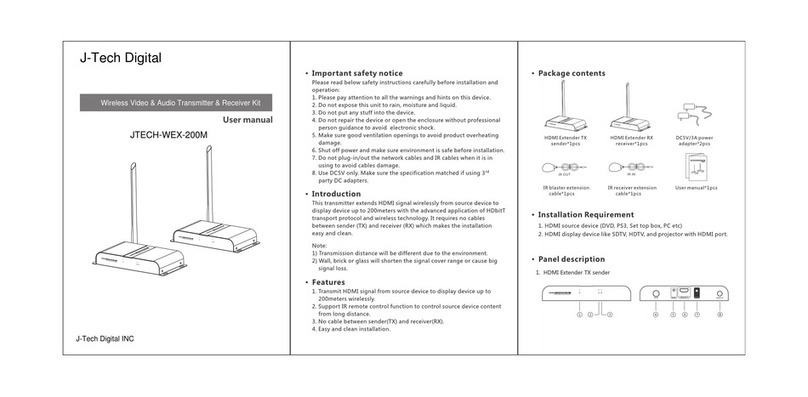
J-Tech Digital
J-Tech Digital JTECH-WEX-200M user manual
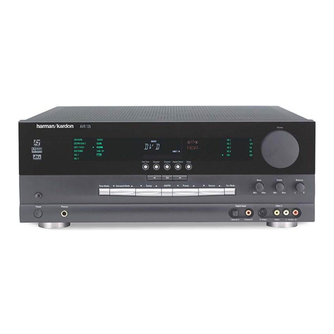
Harman Kardon
Harman Kardon AVR 125 Brochure & specs
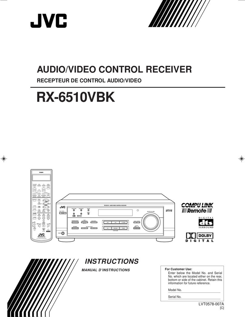
JVC
JVC RX-6510VBK instructions
CADDX
CADDX xGenConnect NXG-9-RF Programming and Configuration Guide

Harman Kardon
Harman Kardon AVR 7300 Service manual

His Master's Voice
His Master's Voice JB-1G operating instructions
