Hexagon VERIPOS LD900 User manual

AB-V-MA-650 1 February 2021
JF/RR 1
LD900 and INS Commissioning Guide
Introduction
This commissioning guide will provide the information required to install the VERIPOS LD900 unit withINS, by
detailing howan LD900 should be configured and how an IMU should be mounted, interfaced and configured.
Contents
Introduction
Prerequisites
INS Authorisation
GNSS Heading Antenna Installation
Reference Frames
IMU Placement
IMU Interfacing
Alignment / Calibration
Rotational Offset Adjustment
Configuration
Operation
Troubleshooting
Appendix A –Equipment Required
Appendix B - IMUPerformance
The VERIPOS INS systemconsists ofan LD900 (LD900 or LD900M model) receiver, authorised forINS use
and operating in PPP mode with active GNSS heading. The LD900 presently supports integration with two
Novatel IMU models, the IMU-ISA-100C and IMU-µIMU-IC:
Novatel IMU-ISA-100C (left) and Novatel IMU-µIMU-IC (right)
INS operations can be configured and monitored using the LD900 MMI, or an interfaced Quantum software
system. This guide will provide details for both options.

AB-V-MA-00650 01 February 2021
JF/RR 2
LD900 and INS
Commissioning Guide
Prerequisites
Prior to starting LD900 and INS commissioning the system must:
1. Have a high-quality antenna installation.
2. Have an AUTH code for INS (which includes Heading)
3. Be activated and receiving VERIPOS PPPcorrection services.
Appendix-A provides a comprehensive equipment listing including part numbers. Alsorefer to the LD900 and
Quantum documentation section in VOSSifrequired.
INS Authorisation
The LD900 must be correctly authorised before it can be used for INS operations. If required obtain an INS
authorisation code by contacting yourVERIPOSproject manager,or by email
(support.veripos@hexagon.com). The Auth Code will be supplied witha guide explaining how the codes can
be applied to the LD900. Note the INS authorisation code includesthe GNSSheading functionality.
A simple way to check if the LD900 is authorised for INS operations is tocheck if INS is presenton the LD900
status screen, asshown in the above image. If there is no INS status iconvisible, then the LD900 is notyet
authorised forINS use.
GNSS Heading Antenna Installation
Consideration for the placement ofthe primary and secondary antennasis required to ensure reliable and
accurate LD900 GNSS reception and heading calculation. Please also consider the INS installation
requirements detailed in sectionIMU Placement.
AntennaSeparation
The GNSS heading accuracy is largely determined by the distance between the primary and secondary
antennas. The larger the antenna separation, the better the heading accuracy will be.VERIPOSrecommend a
minimum antenna separation of2m.
Antenna Separation
Accuracy
2m
0.08°
4m
0.05°
10m
0.02°

AB-V-MA-00650 01 February 2021
JF/RR 3
LD900 and INS
Commissioning Guide
Antenna Installation
Optimum results will be easier to achieve with an along ship installation. The heading orientation is computed
from the GNSS1 antenna toGNSS2 antenna as illustrated below. In this configuration,the GNSSheading
closely reflects the actual vessel heading.A smalloffset (or C-O)must be applied to the LD900.
Along ship antenna installation
Where along ship installation isnot possible, GNSS1 and GNSS2 can be installed across-ship.The offset
would need to align the GNSS heading to the alignment ofthe actualvessel heading. In the example below,
this will typically be around 90° offfrom the true vessel heading:
Across-shipantenna installation
When the LD900 is authorised for INS operations there will be no dedicated Heading icon, asthiswill have
been replaced by the INS icon. However, the GNSS heading status can be checked byselecting the INS icon
and pressing tick.The heading calculation will always be shown irrespective ofthe INS status and
measurements.
LD900 Status page (left) and Status > INS page (right)
GNSS1
GNSS2
Vessel
Heading
GNSS1
GNSS2
Vessel
Heading
AB-V-MA-00650 01 February 2021
JF/RR 4
LD900 and INS
Commissioning Guide
Reference Frames
It is important to have a basic understanding ofreference frames when dealing with INS. Reference frames are
especially important when configuring the systems rotational offsets.Two types ofreference frames will be
considered, the VesselReference Frame and the IMU Body Frame.
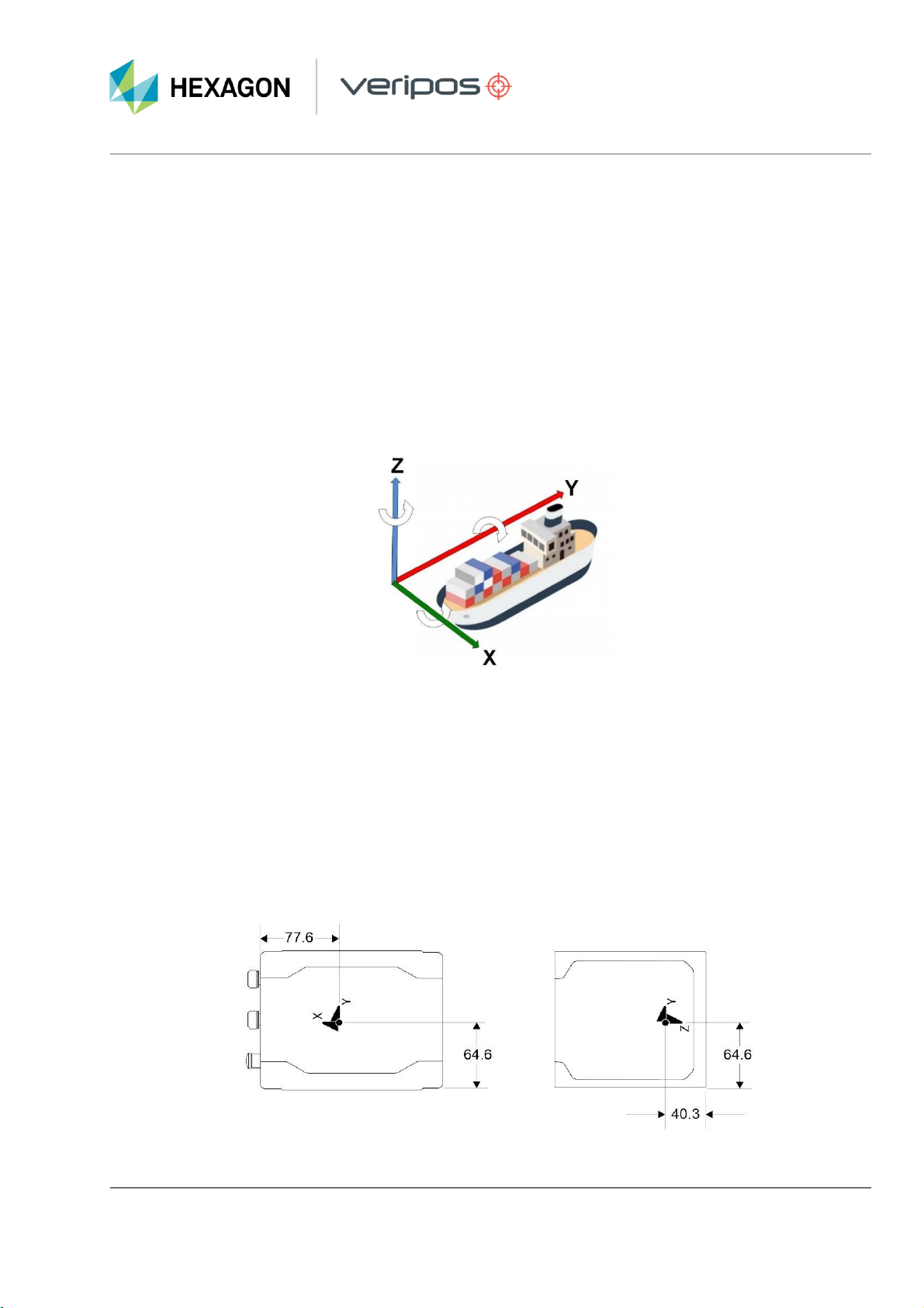
VesselReferenceFrame
The definition of the Vessel Frame is as follows:
X-axis –points out the starboard side ofthe vessel
Y-axis –points out the front ofthe vessel in the direction oftravel
Z-axis –points up vertically on the vessel
Vessel Reference Frame
IMU Body Frame
The definition of the IMU Body frame is given by the physical axesofthe IMU and represents how the sensors
are mounted inside the IMU. Both the IMU Body frame axes and Centre ofNavigation markers are on two of
the IMU enclosure sides
The Centre of Navigation markers highlight the centre ofthe Rotational axesofthe IMU, the actualcentre of
navigation lies internally in the IMU where the XYZ rotational axes intersect. Therefore, If the user measures all
translational offsets to a single Centre ofNavigation marker then twoofthe translational offsetsmust be
adjusted to be aligned with the Centre ofNavigation. The figure below illustrates the position of the Centre of
Navigation markers and the dimensions in millimetres.
IMU-ISA-100C Centre of Navigation Markers
AB-V-MA-00650 01 February 2021
JF/RR 5
LD900 and INS
Commissioning Guide
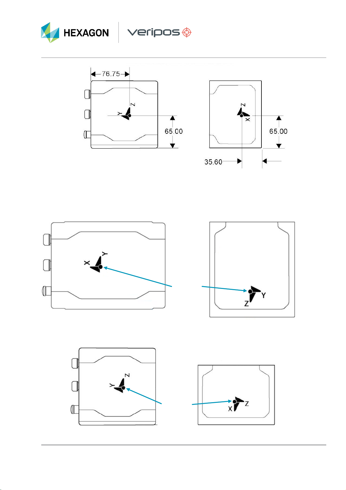
IMU-µIMU-IC Centre of Navigation Markers
IMU-µIMU-IC Centre of Navigation Markers
The two figures following show the IMU Body Frame for both supported IMU models. Thesediagrams highlight
the centre ofnavigation differences between the IMU-ISA-100Cand IMU-µIMU-IC models. The different IMU
frameworks have pre-configured rotational offsets applied by the system configuration when selected, with the
premise ofthe IMU being mounted with the connectorsfacing forward along the vessel frame Y-axis.
PLAN VIEW
REAR VIEW
PLAN VIEW
REAR VIEW
IMU-ISA-100C IMU Body Frame
CENTRE OF
NAVIGATION
CENTRE OF
NAVIGATION
IMU-µIMU-IC Body Frame
AB-V-MA-00650 01 February 2021
JF/RR 6
LD900 and INS
Commissioning Guide
IMU Placement
The following factors need to be considered when installing the IMU.
•Mount as close as possible to the vessel centre point ofgravity
•Mounted on a fabricated plate secured to a flat level surface within the vessel frame.
•Mounted with connectors facing forward
•The IMU base plate must have clearance to allow IMU to be securelybolted.
•Mount in a secure location where it will not be damaged
•Avoid locations thathave a strong vibration.
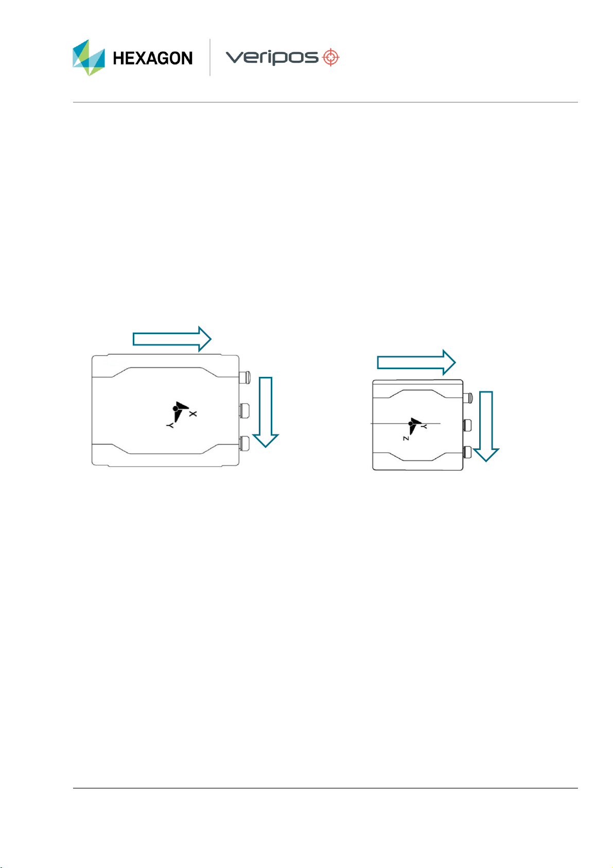
•The installation engineer should endeavourto align the IMU axes as closely as possible with the
vessel frame using a general arrangement diagram, or by referencing available surfaces such as walls
or floor welds. Referto the below figure, following the arrows to orientate the IMU with the vessel
frame:
IMU-ISA-100C –Plan View IMU-µIMU-IC - Plan View
As shown below, the IMU baseplates feature four mounting holes, threaded for M6 bolts. The IMU must be
securely bolted to the IMU baseplate on a level surface, with the connectorsfacing forward to the vessel
bow. By mounting the IMU in a fixed position a constant distance and orientation between the IMU to the
GNSS antenna can be maintained.
FORWARD
STARBOARD
FORWARD
STARBOARD

AB-V-MA-00650 01 February 2021
JF/RR 7
LD900 and INS
Commissioning Guide
When the IMU has been mounted in the correct orientation, pre-setrotational offsets willbe automatically
applied (when the IMU is selected within the LD900 or Quantum),aligning the IMU Frame with the Vessel
Frame. Any computed offsets should be added or subtracted from these pre-set values. The pre-set rotational
offsets forthe two models are shown in the table below:
IMU
X Rotation
Y Rotation
Z Rotation
IMU-ISA -100C
+180
0
+90
IMU-µIMU-IC
0
-90
0
IMU-ISA-100C Base Plate
IMU-µIMU-IC Base Plate

AB-V-MA-00650 01 February 2021
JF/RR 8
LD900 and INS
Commissioning Guide
IMU Interfacing
Cabling
The LD900 will be interfaced to the IMU using RS422 serial data-communications. This section details the
LD900 and IMU requirements forINS operations. The diagram below provides an overview of the principal
system component interconnections:
INS Schematic Example
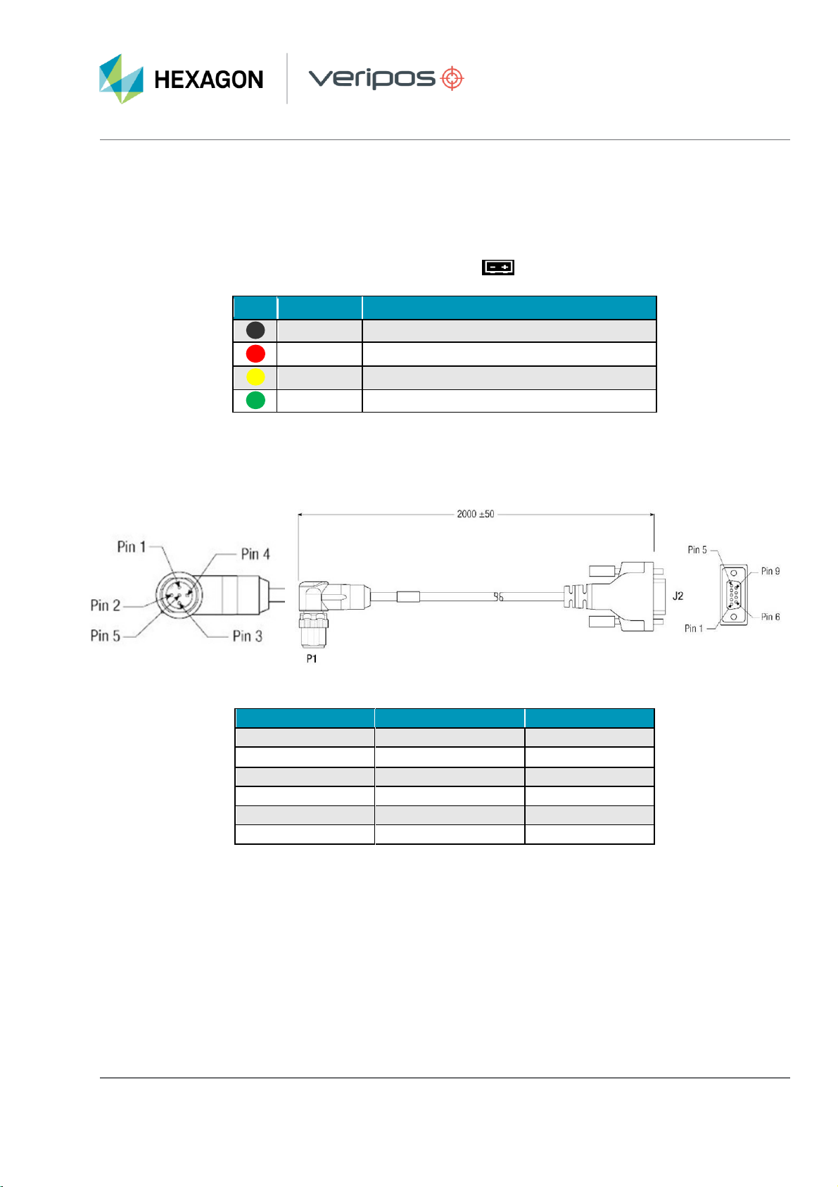
IMU DC Power
A 2-metre long DC power supply cable is supplied with the IMU, this consistsofan M12 Male connectorto five
bare cable ends as shown below:
IMU port pinout
P1 Pinout (M12)
Function
Wire Colour
1
VIN-
Brown
2
VIN+
White
3
VIN+
Blue
4
VIN-
Black
5
Chassis
Grey
Power Cable Schematics (inmm)
AB-V-MA-00650 01 February 2021
JF/RR 9
LD900 and INS
Commissioning Guide
Two isolated DC powersources can be used to power the IMU. Alternatively, the two VIN- and two VIN+ pins
can be connected in parallel and connected to a single DCpower supply. Ensure thatthe positive is connected
to VIN+ and that negative is connected to VIN-. The supply voltage must be within the range of10 to 38 VDC.
Chassis can be connected to a common earthing point in an equipmentrack.
When checkingthe health ofthe IMU DCpower, the Power( ) LED on the IMU can be used as reference:
RS422 Interfacing
A 2-metre long interface cable is supplied with the IMU, this consists ofan M12 Male connector (IMU) to a DB9
Male connector (LD900):
Supplied INS RS422 Data Cable (dimensions in mm)
P1 Pinout (M12)
Function
J2 Pinout (DB9)
1
TX+
2
2
RX+
3
3
TX-
8
4
RX-
7
5
GND
5
Chasis
Shield
Shield
LED
State
Meaning
Off
No power to IMU
On
An error occurred during boot or initialisation
SlowFlash
Booting up / IMU initialisation
On
No error occurred during boot orinitialisation
IMU Power LED
RS422 cablepinouts

AB-V-MA-00650 01 February 2021
JF/RR 10
LD900 and INS
Commissioning Guide
With the use ofquality shielded data cable, theRS422 interface cable should not exceed 50 metres. Avoid
running the interface cable close to noisy power lines, or otherelectrical noise sources.
When checkingthe IMU health the COM ( ) LED on the IMU can be used as a reference:
LED
State
Meaning
Off
No communication between IMU and LD900
On
IMU is transmittingand receiving data without errors
SlowFlash
IMU is receiving data from the LD900 but not transmitting
Fast Flash
IMU is transmittingdata but not receiving data from the LD900
IMU COM LED

AB-V-MA-00650 01 February 2021
JF/RR 11
LD900 and INS
Commissioning Guide
Alignment / Calibration
The IMU and antenna placements must be aligned to the vessel frame. The system configuration requires the
following measurements;
•Lever arm (IMU to Antenna 1)
oX (Starboard Positive)
oY (Forward Positive)
oZ (Up Positive)
•Heading
oRotational offset from GNSS1 to GNSS2 antennas
•IMU Rotational Offsets
oX (Pitch)
oY (Roll)
oZ (Yaw)
Precise offsets can be determined by performing a dimensional controlsurvey ofthe vessel while alongside or
in dock. The dimensional survey measurements should be taken using an independentsystem, free of
installation or misalignment errors.
In addition to the IMU rotational offsets, the heading alignment offset should also be computedbetween the
two GNSS antennas and these results used to adjust the rotational offsets to precise values.
Note: If the rotational offsets are greaterthan +/- 1⁰accuracytheINS computationsmaystill initialise,but the
solution will be negatively impacted and not maintain a converged solution, once vessel motion occurs.
It is also important to accuratelymeasure the lever arm distance (XYZ) from the IMU centre ofnavigation to
the antenna reference point (ARP) ofthe GNSS1 antenna. These translational offsets can be measured as
part of the dimensional survey. Ensure the ARPto phase centre Zoffset is adjusted in the final application of
the offsets. The translational offset measurements must be accurate towithin +/- 1cm.
To fully calibrate and converge the systemforthe active PPP solution to use INS aiding vessel movement will
be required. Typical vessel movement during transit will be adequate for convergence, this calibration will take
several minutes up to 10 minutes. This calibration process is performed automatically by the system and does
not require any userinteraction. Where calibration istaking a prolonged period, the vessel should perform
figure of 8 movement.

AB-V-MA-00650 01 February 2021
JF/RR 12
LD900 and INS
Commissioning Guide
INS Translational Offsets
AB-V-MA-00650 01 February 2021
JF/RR 13
LD900 and INS
Commissioning Guide
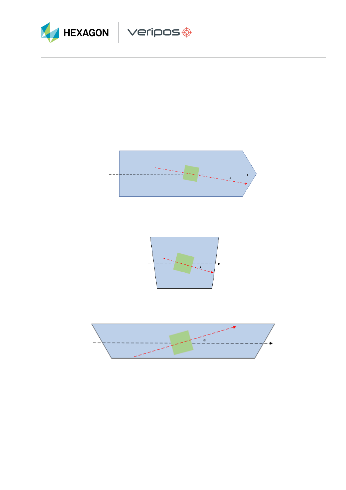
Rotational Offset Adjustment
This section will illustrate how the measured rotational alignment offsets (precise offsets) should be adjusted to
the default course offset. The following illustratesthe adjustments methods for both supported IMU models.
IMU-ISA-100C
When the Xaxis of the IMU is offset to starboard by angle “a”. The Installation Rotation Z +90 value is reduced
by the measured angle:
When the Y axis ofthe IMU is offset down to the starboard by angle “a”. The Installation Rotation X+180 value
is reduced by the measured angle:
When the Zaxis ofthe IMU is offset up to the bow by angle “a”. The Installation Rotation Y 0 value is reduced
by the measured angle:
INS Rotational Offsets –Side View (into Starboard Side)
INS Rotational Offsets –Vessel Plan View
INS Rotational Offsets –Forward View (from vessel Aft)
AB-V-MA-00650 01 February 2021
JF/RR 14
LD900 and INS
Commissioning Guide
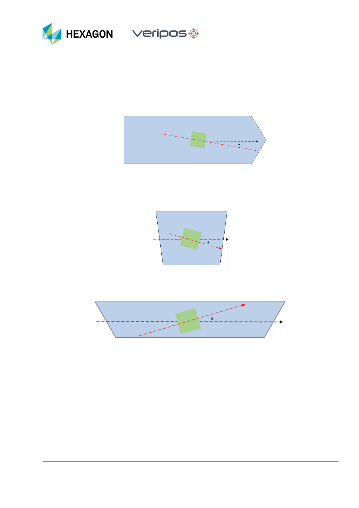
IMU-µIMU-IC
When the Y axis of the IMU is offset to starboard by angle “a”. The Installation Rotation X 0 value is reduced
by the measured angle.
INS Rotational Offsets –Vessel Plan View
When the Z axis oftheIMUis offset to starboard by angle “a”. The Installation Rotation Y -90 value is reduced
by the measured angle (Ifthe measured value for ‘a’was 10 degrees the value would reduce to -100)
When the X axis of the IMU is offset to starboard by angle “a”. The Installation Rotation Z0 value is reduced by
the measured angle.
INS Rotational Offsets –Side View (into Starboard Side)
INS Rotational Offsets –Forward View (into vessel Aft)
AB-V-MA-00650 01 February 2021
JF/RR 15
LD900 and INS
Commissioning Guide
Configuration
At this stage, the IMU is securely mounted with offsets determined, powered up and connected to a LD900
COM port. The LD900 has been activated for PPP solution, which is converged and stable and the LD900 is
ready for configuration. The LD900 can be configured via the MMI as detailed in the next section, or by using
Quantum.
LD900 Configuration
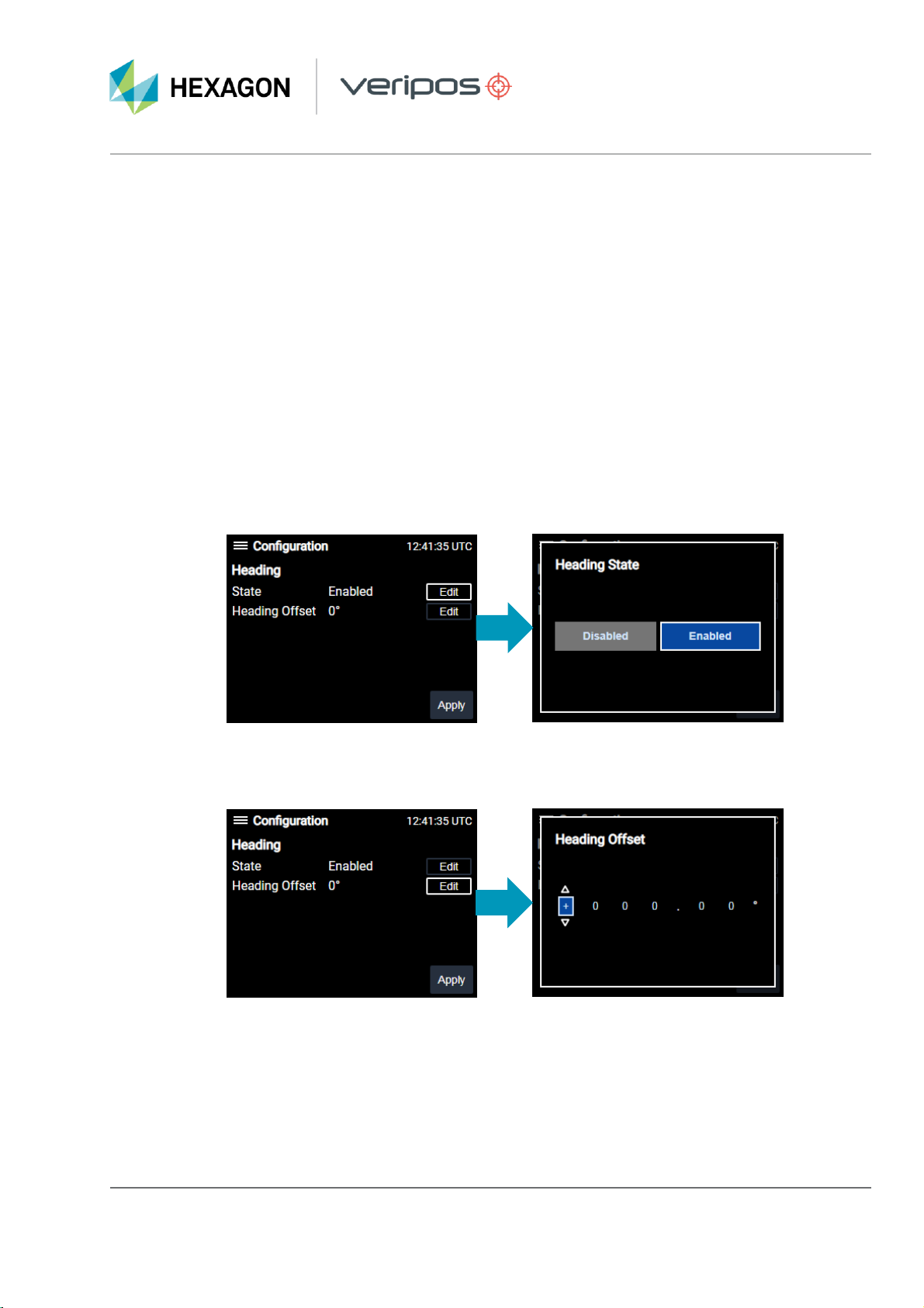
Heading
Accessing the menu Configuration > Heading within the LD900 MMI will allowfor the LD900 heading to be
set-up.
State controls ifheading is computed and available from the system. While Edit on the same row as State is
selected, use tick to bring up the Heading State and using the arrowkeys select Enabled, followed by tick.
Then use the arrowkeys to select Apply, rightto select Yesand tick to apply:
To configure the heading offset (C-O) select Editforthe Heading Offset row, followed by tick. Then use the
arrow buttons and tick to enter the GNSSheading offset. Use the arrow keys to select Apply, right to select
Yes and tick to apply the change:

AB-V-MA-00650 01 February 2021
JF/RR 16
LD900 and INS
Commissioning Guide
Return to the home screen and INS status will be unchanged (grey). The GNSS headingcan be observed
within the INS status. The reported GNSS heading should show alignment with the vesselheading, no other
values will be present at this stage.
IMU Type & Serial Port
Accessing the menu Configuration > INSwithinthe MMI will allow for the LD900 to be set-up forINS
Operations.
The IMU Type can be selected within the menu Configuration > INS.While Edit is selected on the IMU Type
row press tick and using the arrowkeys select IMU-ISA-100C orIMU-µIMU-IC as required, followed by tick.
Then use the arrowkeys and tick to select Apply, right to select Yesand tick to apply the change:
Once the IMU Type has been selected the IMU Port can be selected. While Edit is selected on the IMU Port
row press tick and using the arrowkeys and tick select COM1, COM2 orCOM3 (default)as required, followed
by tick. Then use the arrow keys to select Apply, tick to select Yesand tick to apply the change:

AB-V-MA-00650 01 February 2021
JF/RR 17
LD900 and INS
Commissioning Guide
Installation Rotation
The following details how the X (Pitch), Y (Roll) and Z(Yaw) rotational offsets are entered into the LD900.
While Installation Rotation isselected click on Edit, followed by tick and using the arrow buttonsand tick
enter an Xvalue within +/- 180.00. Use the arrow keys and tick to select Done, then use the arrow keys and
tick to select Apply,right to select Yesand tick to apply the change. Repeat for the same process for the Y
and Zoffsets.
Antenna 1 Offset (Lever-Arm)
When entering the lever arm offset (IMU to GNSS1 antenna) the following table can be used as reference:
While Antenna Offset 1 is highlighted clickon Edit, followed by tick. Then use the arrowbuttonsand tick to
enter an Xvalue within +/- 99.999 meters. Use the arrow and tick keys to select Done, then use the arrow and
tick keys to select Apply, rightto select Yesand tick to apply the change.
Vessel Axis
Positive
Negative
X
Starboard
Port
Y
Forward
Aft
Z
Up
Down
AB-V-MA-00650 01 February 2021
JF/RR 18
LD900 and INS
Commissioning Guide
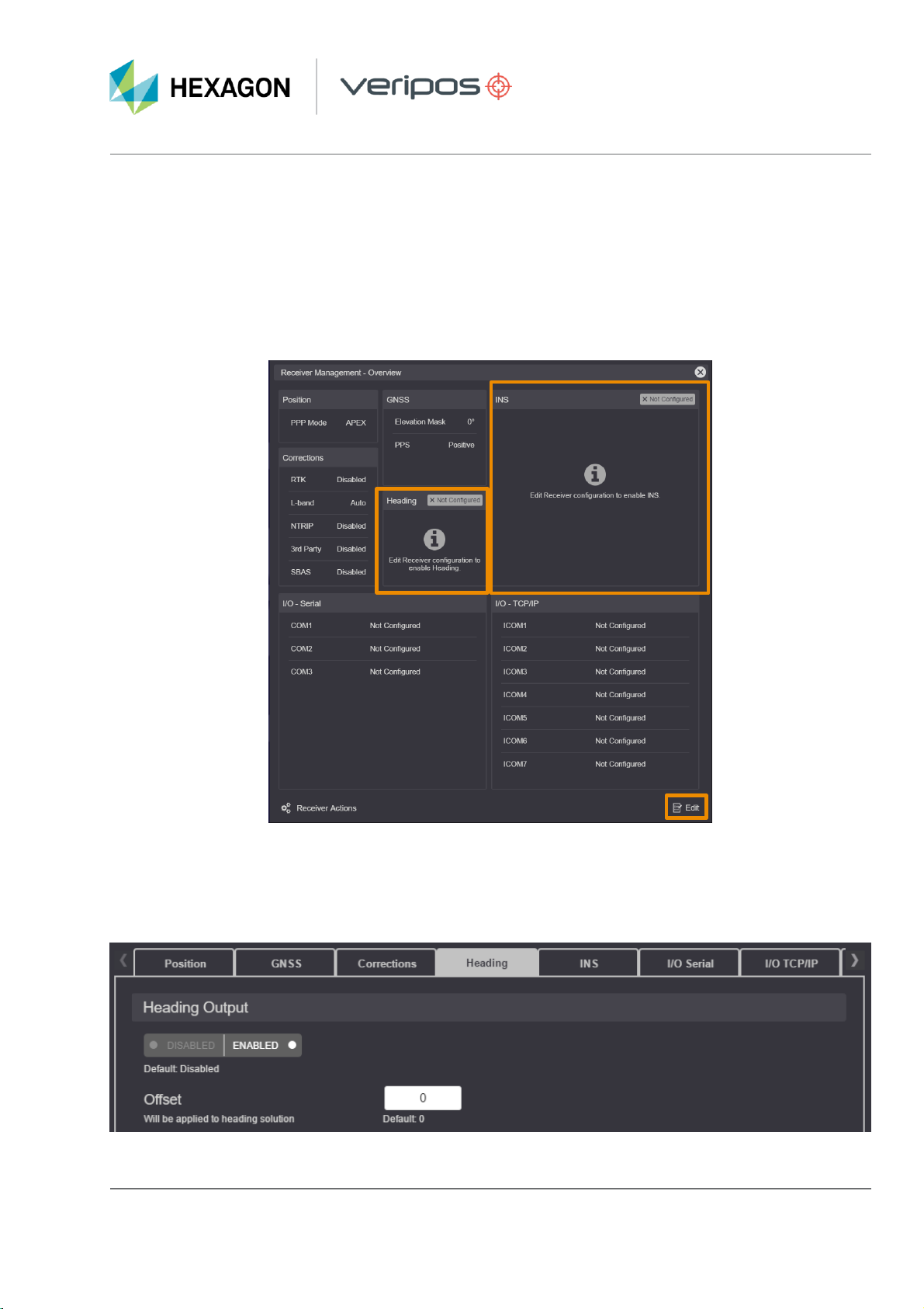
QuantumConfiguration
Receiver Management
When correctlyauthorised both Heading and INSareas will be displayed within SETTINGS> System
Configuration > Receiver Management showing XNot Configured. If no such areas are shown, then
request a Quantum Heading license from the VERIPOS Helpdesk. Click on Edit, foundat thebottom right-
hand corner of the screen:
SETTINGS > System Configuration > Receiver Management –Overview page
Enabling Heading
Within the Headingtab toggle Heading Output to ENABLED. Doing so will reveal the Offset setting where
the GNSS heading offset should be entered. Once heading has been configured click on Apply.
Quantum Heading configuration page

AB-V-MA-00650 01 February 2021
JF/RR 19
LD900 and INS
Commissioning Guide
Enabling INS
Within the INS tab initially, only one optionwill be available, allowing for INS to be DISABLED (or)ENABLED.
Toggle this to ENABLED to reveal additional options:
INS Tab within Quantum
Once all options are fully configured click Apply to confirm changesand apply configuration to the LD900 and
IMU.
Type
The two INS IMUs supported for use within
Quantum are the IMU-ISA-100C and the IMU-
μIMU-IC.
Port
The LD900 COM port which the IMU is being
interfaced on (COM1, COM2 orCOM3) should
be selected here.
IMU Installation> Rotational Offset
This field allows the user to enter Rotational
Offset X,Y and Z values within a -180.00° to
+180.00° range.
IMU to Antenna Offset > Primary Antenna
This field allows the user to enter Primary
Antenna Offset X,Y and Zvalues within a
range of -99.99 to +99.99 metres.
Once INS has been configured click on Apply.

AB-V-MA-00650 01 February 2021
JF/RR 20
LD900 and INS
Commissioning Guide
Operation
The successful configuration ofINS can be determined by checking the LD900 MMI Statuspage and, ifused,
within the Quantum main page.
INS Status (LD900 MMI)
The LD900 INS status can be viewed on the MMI by pressing the home button.
Before configuration, the INS Icon will be Grey and once configured this will change from Grey to Amber. Once
an INS solution is calculated the icon will turn Green and once there has been significantvessel motion an
‘INS Aided’ notification will appear, confirming a blended GNSS and INS solution. If there is a problem with
either the configuration orthe hardware, then the status of the INS Icon will be Red. The INS transition
sequence is illustrated below:
Authorised, not
configured
Configured
and aligning
Aligned
Fully converged and INS
solution active
Selecting the INS statuswith the cursor and presenting tick willreveal additional details. Once the INS solution
is operational the GNSS heading will closely match the INS heading.
INS Status details
Other manuals for VERIPOS LD900
2
This manual suits for next models
1
Table of contents
Other Hexagon Receiver manuals


