HH Electronics TESSEN TNA-1200S-G2 User manual
TNA-2051& TNA-1200S-G2
USER MANUAL
LIVE SOUND & INSTALLATION
DESIGNED AND ENGINEERED IN THE UK
WWW.HHELECTRONICS.COM

Designed and Engineered in the UK by HH Electronics LTD.
© 2022 HH Electronics Ltd
LINE ARRAY LIVE SOUND & INSTALLATION
2
CONTENTS / CONTENU / INHALT / CONTENIDO / CONTEÚDO /
5.________________________ SIDE BRACKET - STACKING
6.________________________ TNA-BRK1 - FLYING BRACKET
7.________________________ SAFETY
1.________________________ COVER PAGE
2.________________________ CONTENTS
4.________________________ INTRODUCTION/REAR PANEL
3.________________________ GENERAL INSTRUCTIONS
11._______________________ TNA-1200S - SPECIFICATIONS / CABINET DIMENSIONS
12._______________________ TNA-2051 - SPECIFICATIONS / CABINET DIMENSIONS
10._______________________ 2 CHANNEL SETUP
13-18.____________________ LANGUE FRANÇAISE
8.________________________ TNA-DF1 - DOLLY BOARD
9.________________________ 4 CHANNEL SETUP
19-24.____________________ DEUTSCHE SPRACHE
25-30.____________________ LENGUA ESPAÑOLA
31-36.____________________ IDIOMA PORTUGUES
37-42.____________________ 中文
43-48.____________________ 한국어
EN
EN
EN
EN
EN
EN
EN
EN
EN
EN
EN
EN
EN
EN
EN
EN
FR
EN
EN
EN
EN
DE
ES
PT
CN
EN
KR
© 2022 HH Electronics Ltd
LINE ARRAY
Designed and Engineered in the UK by HH Electronics LTD.
LIVE SOUND & INSTALLATION
CAUTION:
WARNING:
1) Unpacking: On unpacking your product please check carefully for any signs of damage that may have occurred whilst in transit from the HH factory to your dealer. In the unlikely
event that there has been damage, please re-pack your unit in its original carton and consult your dealer. We strongly advise you to keep your original transit carton, since in the unlikely
event that your unit should develop a fault, you will be able to return it to you dealer for rectification securely packed.
In order to take full advantage of your new product and enjoy long and trouble-free performance, please read this owner's manual carefully, and keep it in a safe place for future reference.
By turning on your amplifier LAST and making sure its level control is set to a minimum, any transients from other equipment should not reach your loud speakers. Wait till all system parts
have stabilised, usually a couple of seconds. Similarly when turning off your system always turn down the level controls on your bass amplifier and then turn off its power before turning off
other equipment
4) Servicing: The user should not attempt to service these products. Refer all servicing to qualified service personnel.
2) Amplifier Connection: In order to avoid damage, it is advisable to establish and follow a pattern for turning on and off your system. With all system parts connected, turn on source
equipment, tape decks, cd players, mixers, effects processors etc, BEFORE turning on your amplifier. Many products have large transient surges at turn on and off which can cause damage
to your speakers.
3) Cables: Never use shielded or microphone cable for any speaker connections as this will not be substantial enough to handle the amplifier load and could cause damage to your
complete system.
GENERAL INSTRUCTIONS
RoHS (2011/65/EU), ErP (2009/125/EU).
---------------------------------------------------------------------------------
In order to reduce environmental damage, at the end of its useful life, this product must not be disposed of along with normal household waste to landfill sites. It must be taken to an
approved recycling centre according to the recommendations of the WEEE (Waste Electrical and Electronic Equipment) directive applicable in your country.
---------------------------------------------------------------------------------
--------------------------------------------------------------------------------
This product conforms to the requirements of the following European Regulations, Directives & Rules:
CE Mark (93/68/EEC), Low Voltage (2014/35/EU), EMC (2014/30/EU),
http://support.hhelectronics.com/approvals
15. Never break off the ground pin. Connect only to a power supply of the type marked on the unit adjacent to the power supply cord.
14. Refer all servicing to qualified service personnel. Servicing is required when the apparatus has been damaged in any way, such as when power-supply cord or
plug is damaged, liquid has been spilled or objects have fallen into the apparatus, the apparatus has been exposed to rain or moisture, does not operate
normally, or has been dropped.
16. If this product is to be mounted in an equipment rack, rear support should be provided.
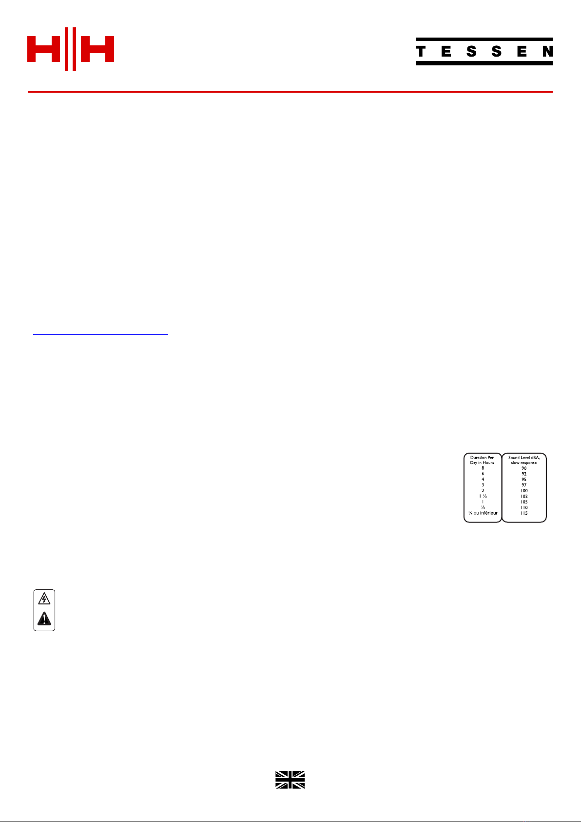
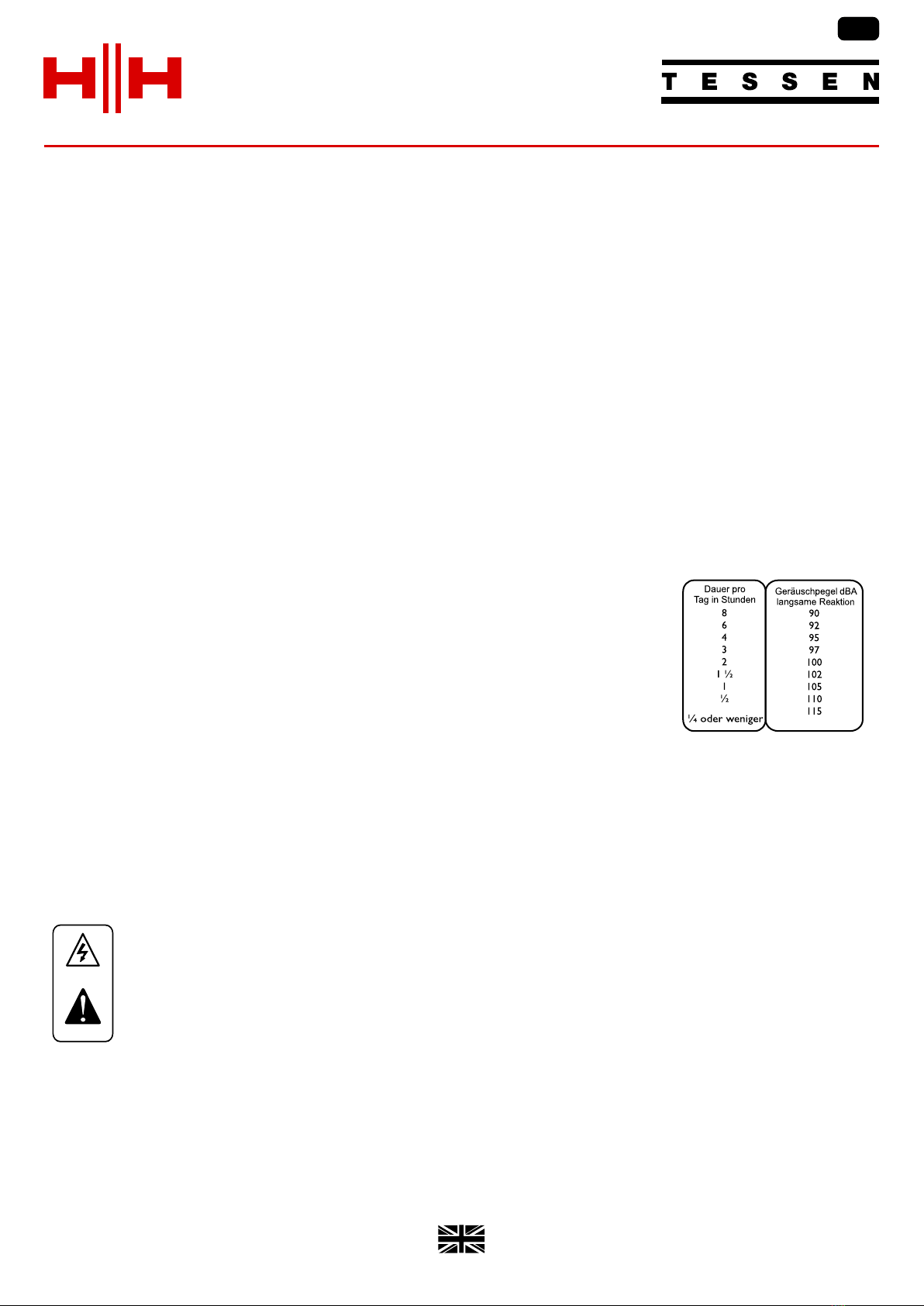
The U.S. Government’s Occupational Safety and Health Administration (OSHA) has specified the following permissible noise level exposures: According to OSHA, any exposure in excess of the
above permissible limits could result in some hearing loss. Earplugs or protectors to the ear canals or over the ears must be worn when operating this amplification system in order to prevent a
permanent hearing loss, if exposure is in excess of the limits as set forth above. To ensure against potentially dangerous exposure to high sound pressure levels, it is recommended that all
persons exposed to equipment capable of producing high sound pressure levels such as this amplification system be protected by hearing protectors while this unit is in operation.
12. Use only with a cart, stand, tripod, bracket, or table specified by the manufacturer, or sold with the apparatus. When a cart is used, use caution when moving the cart/apparatus combination to
avoid injury from tip-over.
18. Exposure to extremely high noise levels may cause a permanent hearing loss. Individuals vary considerably in susceptibility to noise-induced hearing loss, but
nearly everyone will lose some hearing if exposed to sufficiently intense noise for a sufficient time.
20. Symbols & nomenclature used on the product and in the product manuals, intended to alert the operator to areas where extra caution may be necessary, are as follows:
17.This electrical apparatus should not be exposed to dripping or splashing and care should be taken not to place objects containing liquids, such as vases, upon
the apparatus.
13. The mains plug or appliance coupler is used as the disconnect device and shall remain readily operable. The user should allow easy access to any mains plug,
mains coupler and mains switch used in conjunction with this unit thus making it readily operable. Unplug this apparatus during lightning storms or when
unused for long periods of time.
Risk of electrical shock - DO NOT OPEN. To reduce the risk of electrical shock, do not remove the cover. No user serviceable parts inside. Refer servicing to qualified personnel.
To prevent electrical shock or fire hazard, do not expose this appliance to rain or moisture. Before using this appliance please read the operating instructions.
Intended to alert the user of the presence of important operating and maintenance (Servicing) instructions in the literature accompanying the product.
.
Intended to alert the user to the presence of high ‘Dangerous Voltage’ within the products enclosure that may be sufficient to constitute a risk of electrical shock to persons.
3. Heed all warnings.
6. Clean only with a dry cloth.
11. Only use attachments/accessories provided by the manufacturer.
1. Read these instructions.
2. Keep these instructions safe.
5. Do not use this apparatus near water.
8. Do not install near any heat sources such as radiators, heat registers, stoves or other apparatus (including amplifiers) that produce heat.
7. Do not block any of the ventilation openings. Install in accordance with manufacturer’s instructions.
9. An apparatus with Class I construction shall be connected to a mains socket outlet with a protective connection. Do not defeat the safety purpose of the polarized or grounding-type plug. A
polarized plug has two blades with one wider than the other. A grounding type plug has two blades and a third grounding prong. The wide blade or third prong is provided for your safety. If the
provided plug does not fit into your outlet, consult an electrician for replacement of the obsolete outlet.
4. Follow all instructions.
10. Protect the power cord from being walked on or pinched, particularly at plugs, convenience receptacles, and the point they exit from the apparatus.
3

Designed and Engineered in the UK by HH Electronics LTD.
© 2022 HH Electronics Ltd
LINE ARRAY LIVE SOUND & INSTALLATION
3
REAR PANEL - I/O
INTRODUCTION
TNA-1200S-G2
The TNA range comprises of TNA-2051; Dual HH designed 5” two-way passive line array speaker with custom designed Celestion
compression driver and wave guide, the TNA-1200S-G2 and TNA-1800S-G2, 12” and 18” (respectively) high performance passive
subwoofers.
With live sound applications increasing in demand, users require more from their audio system. The TNA mini line array provides
high output within a compact system. Suitable as either a permanently installed sound system or for portable use, the TNA mini line
array delivers crystal clear dynamics.
TNA mini line array – the perfect mobile or installed audio solution.
Along with the TNA speaker enclosures are premium constructed accessories. The TNA-BRK1 solid steel flying bracket provides
secure suspension of the TNA system when installed. The TNA-DF1 wheeled dolly frame attaches to the TNA-1200S-G2 providing
flexible transport of a stacked system.
3: M4 TERMINAL CONNECTORS: Provided for additional wiring flexibility. These are internally connected to the NL4
connectors as can be seen in the diagram below.
1: INPUT: To be connected to the Output of your chosen amplifier. Check the technical specification of your amplifier to ensure its
drive capability and output power are suitable for use with a TNA-1200S-G2 cabinet.
As with the TNA-1800S-G2, both the TNA-1200S-G2 and TNA-2051 feature NL4 ±1 Twist Lock Connectors with additional M4
terminal connectors on the TNA-1200S-G2.
DO NOT CONNECT A SECOND AMPLIFIER TO THE LINK OUTPUT OR THE M4 TERMINAL CONNECTORS!
2: LINK: Connected in parallel with the INPUT connector allowing for additional cabinets to be added to the speaker chain.
TNA-2051
WIRING
± 1 INPUT
± 2 N/A
INPUT LINK
DESIGNED AND ENGINEERED
IN THE UK BY
WWW.HHELECTRONICS.COM SN:ABC1234567890
MODEL: TNA-2051
WIRING
± 1 INPUT
± 2 N/A
INPUT LINK
DESIGNED AND ENGINEERED
IN THE UK BY
WWW.HHELECTRONICS.COM
MADE IN CHINA
+
-
+
-
IMPEDANCE
POWER AES
CONTINUOUS
POWER PEAK
8Ω
300W
600W
1200W
SN:ABC1234567890
MODEL: TNA-1200S-G2
4
SYSTEM DIAGRAMS
FREN
EN
1
1
2
2
DRIVERS
HF
LF
LF
1
11
+
++
2+
2+2+
LINK
2+
2+2+
1+
1+1+
INPUT
++
+
X-OVER
1
11
1
11
2
22
2
22
(LINK)
(INPUT)
LF DRIVER
1+
1+1+
2+
2+2+
LINK
1
11
2
22
2+
2+2+
1+
1+1+
INPUT
1
11
2
22
+
++
+
++
+
++
+
++
© 2022 HH Electronics Ltd
LINE ARRAY
Designed and Engineered in the UK by HH Electronics LTD.
LIVE SOUND & INSTALLATION
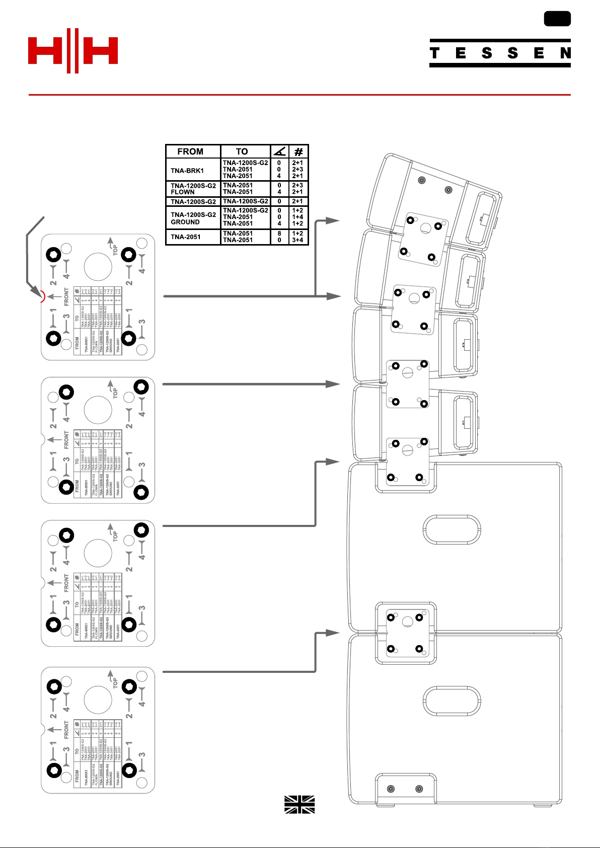
The TNA side bracket is used to provide the mechanical fixing/support between TNA-1200S-G2 sub cabinet and TNA-2051
satellite cabinets. Depending on the combination of holes used, a horizontal or angled arrangement can be achieved.
The fit options are printed on
the side bracket.
In all instances, the location
notch should point towards the
front face of the cabinet.
5
FREN
EN
1+2
3+4
1+4
1+2
Designed and Engineered in the UK by HH Electronics LTD.
© 2022 HH Electronics Ltd
LINE ARRAY LIVE SOUND & INSTALLATION
6
KIT CONTENTS
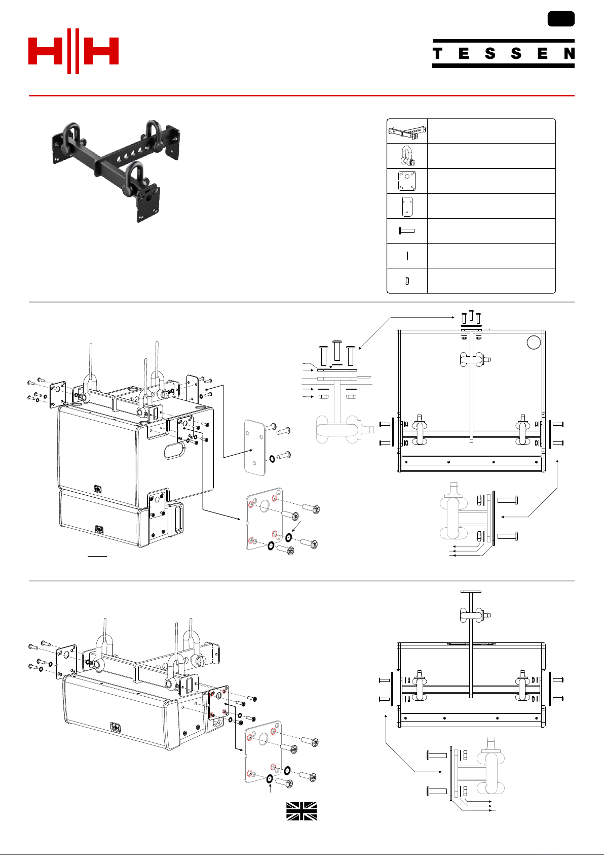
FLYING BRACKET - TNA-1200S-G2
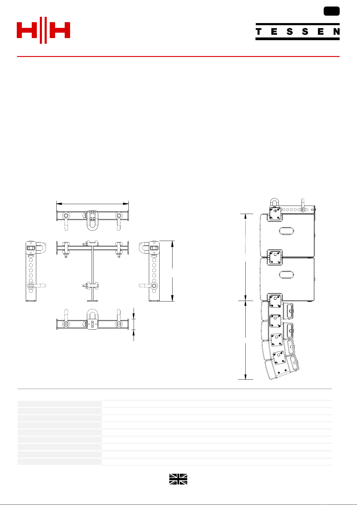
The TNA-BRK1 flying bracket for use with the TNA-1200S-G2 and TNA-2051.
With its solid steel construction, the TNA-BRK1 securely supports up to two
TNA-1200S-G2 and eight TNA-2051 enclosures simultaneously.
The TNA-BRK1 is attached to the TNA-1200S-G2 using two Side Brackets and one Rear Bracket.
As with the TNA-1200S-G2, spring washers
must be used with all screws!
Spring washers must be used with each screw!
Be extremely careful to not cross thread the side screws when filling the brackets!
TNA-BRK1 - FLYING BRACKET
FLYING BRACKET - TNA-2051
LOCKNUT
SPRING WASHER
SPRING WASHER
REAR BRACKET
LOCKNUT
SPRING WASHER
SIDE BRACKET
1 x Lift Bracket assembly
3 x D-shackle
2 x Side plate
1 x Rear plate
7 x M8x25mm connector bolt
6 x M8 lock nuts
7 x Spring washers
LOCKNUT
SPRING WASHER
SIDE BRACKET
SPRING WASHER
SPRING WASHER
A TNA-2051 requires the use of Side Brackets only.
FREN
EN

© 2022 HH Electronics Ltd
LINE ARRAY
Designed and Engineered in the UK by HH Electronics LTD.
LIVE SOUND & INSTALLATION
7
SAFETY
W
D
H
For added safety, it is strongly recommended that the audio connections, mechanical fixings and mounting brackets
are checked periodically.
The flying of cabinets should be performed only by properly qualified persons, in compliance with all local laws and
using approved hardware.
It is the installers responsibility to ensure the point of fixing is structurally adequate to support the weight of the
cabinets.
The rigging or suspended mounting of these speakers can expose members of the public to serious health risks or
even death.
Under no circumstances attempt to rig, suspend or otherwise mount this system unless you are fully qualified and
certified to do so by relevant local, state and national authorities. All relevant safety regulations must be followed. If
you are not properly qualified or do not know of pertinent regulations, consult qualified personnel for advice and
assistance.
Depending on local regulations, additional pull back supports may be required.
TWO TNA-1200S-G2
UP TO EIGHT TNA-2051
SPECIFICATIONS
TNA-BRK1 MAXIMUM SUPPORT LIMIT
FREN
EN
Model
TNA-BRK1
Suspension Type
The bracket allows you to fit upto three D-shackles (included)
Mounting Type
Five M8 mounting points hold the bracket securely to the cabinet
Max Load Weight
120Kg, 264lbs
Max Unit Load
8x TNA-2051 & 2x TNA-1200S-G2 OR 4x TNA-1200S-G2
Unit dimensions (HWD)
64 x 451 x 340mm, 2.5" x 17.8" x 13.4"
Unit weight
5.6Kg, 12.3 lbs
Carton dimensions (HWD)
145 x 505 x 430mm, 5.7" x 19.9" x 16.9" , 0.031 M3
Packed weight
6.7Kg, 14.8 lbs
In the interest of continued development, HH reserves the right to amend product specification without prior notification.
*extra pull-back support required for more than 4 TNA-2051
Designed and Engineered in the UK by HH Electronics LTD.
© 2022 HH Electronics Ltd
LINE ARRAY LIVE SOUND & INSTALLATION
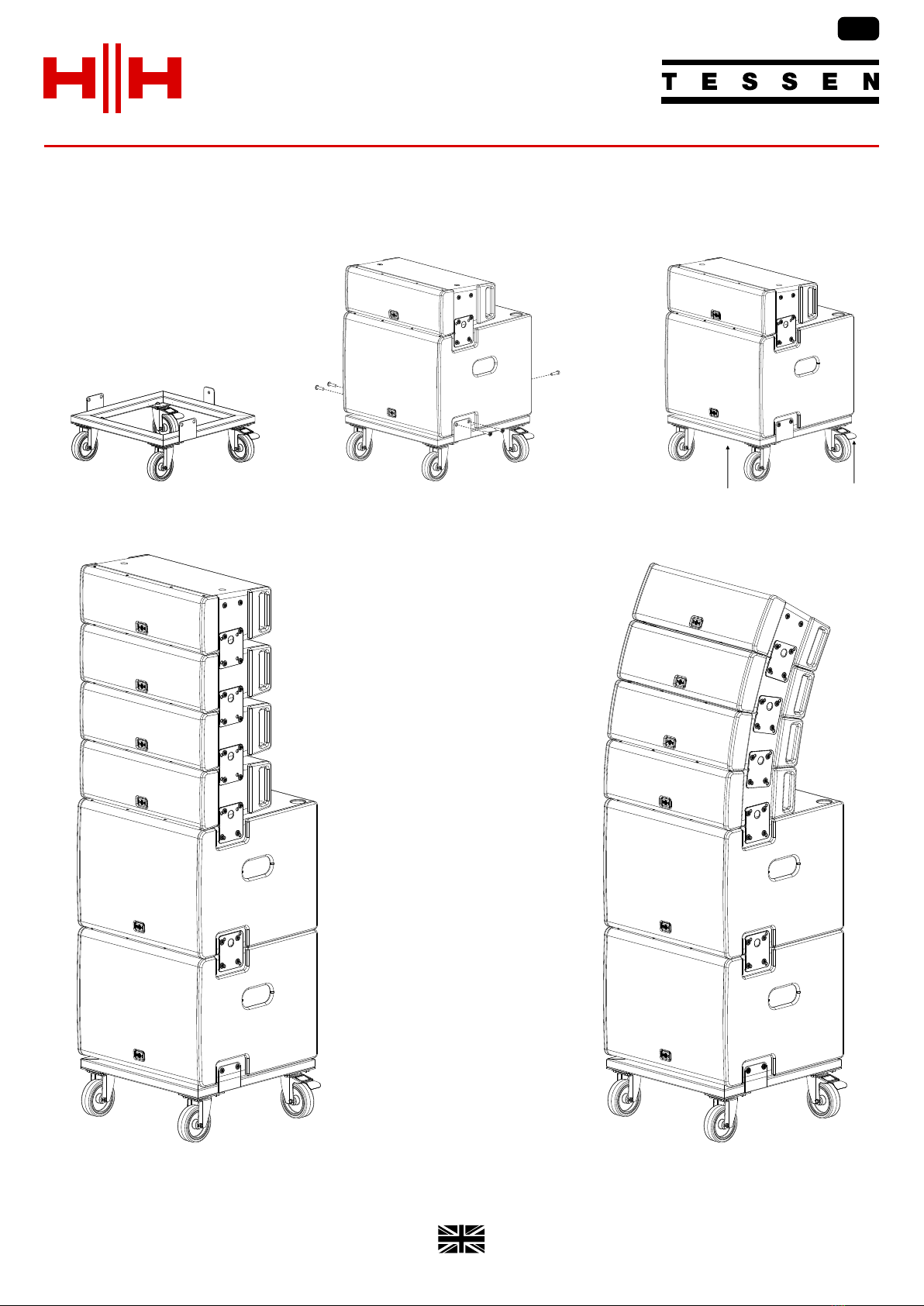
With its lightweight rugged design the TNA-DF1 allows for cabinets to be easily repositioned and configured to suit the
requirement at hand.
PLEASE NOTE: A maximum of four TNA-2051 and two TNA-1200S-G2 should be used on the Dolly Board.
TNA-DF1 - DOLLY BOARD
The TNA-1200S-G2 is secured to
the TNA-DF1 (using two side and one
rear bracket) with six M8 x 20 hex
bolts.
Ensure the breaks are engaged on the
rear wheels once the array has been
suitably positioned.
8
FREN
EN

© 2022 HH Electronics Ltd
LINE ARRAY
Designed and Engineered in the UK by HH Electronics LTD.
LIVE SOUND & INSTALLATION
9
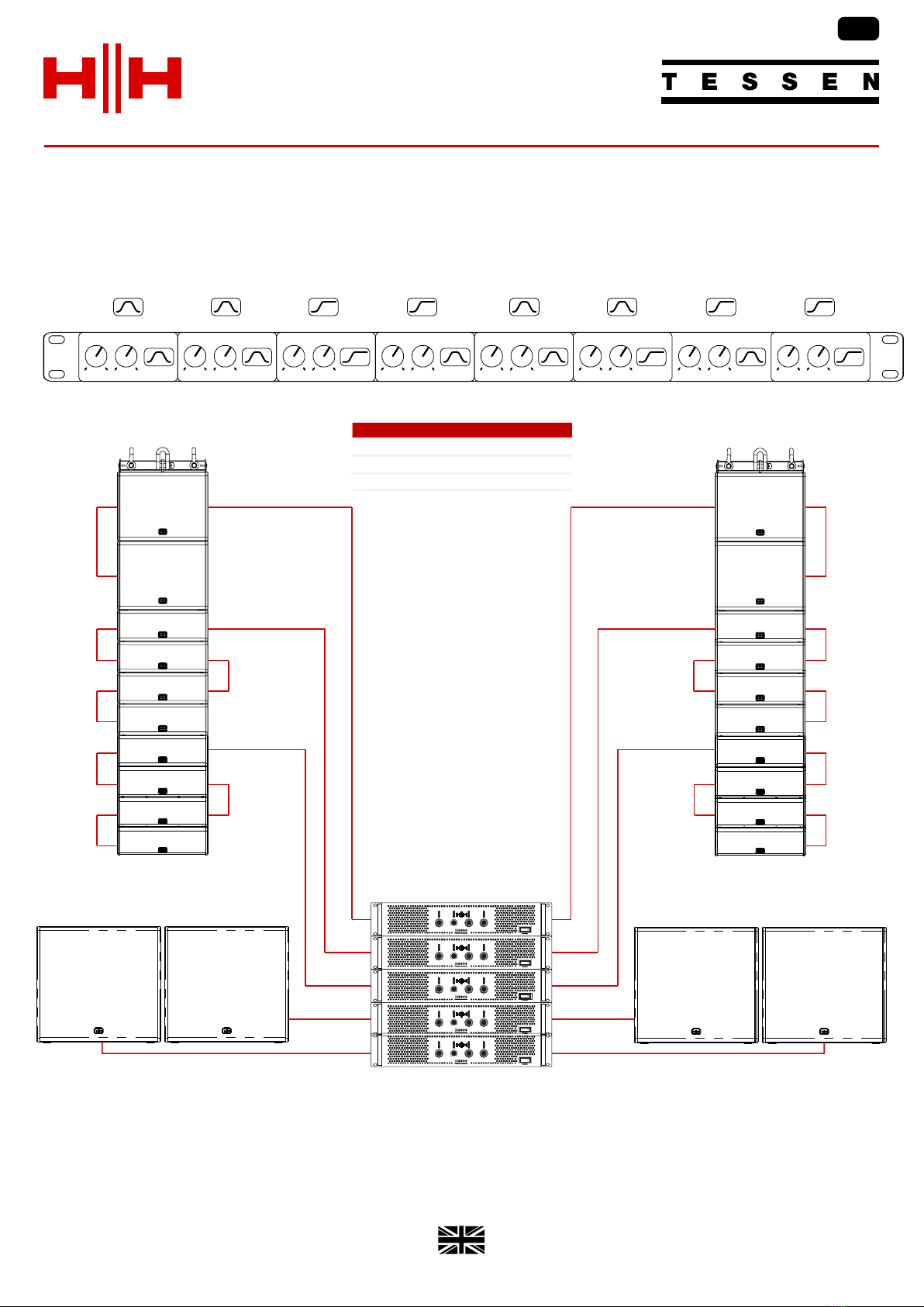
TYPICAL SETUP
FREN
EN
1200S
60>250Hz
1800S
40>120Hz
2051
250Hz
CHANNEL 1
CHANNEL 1CHANNEL 1
FREQUENCY
FREQUENCYFREQUENCY
LEVEL
LEVELLEVEL
CHANNEL 2
CHANNEL 2CHANNEL 2
FREQUENCY
FREQUENCYFREQUENCY
LEVEL
LEVELLEVEL
CHANNEL 3
CHANNEL 3CHANNEL 3
FREQUENCY
FREQUENCYFREQUENCY
LEVEL
LEVELLEVEL
CHANNEL 4
CHANNEL 4CHANNEL 4
FREQUENCY
FREQUENCYFREQUENCY
LEVEL
LEVELLEVEL
CHANNEL 5
CHANNEL 5CHANNEL 5
FREQUENCY
FREQUENCYFREQUENCY
LEVEL
LEVELLEVEL
CHANNEL 6
CHANNEL 6CHANNEL 6
FREQUENCY
FREQUENCYFREQUENCY
LEVEL
LEVELLEVEL
1200S
60>250Hz
1800S
40>120Hz
2051
250Hz
FULL SYSTEM
2x TNA-1200S-G2 Passive Subwoofer
2x TNA-1800S-G2 Passive Subwoofer
8x TNA-2051 Passive Top Line Array Box
Designed and Engineered in the UK by HH Electronics LTD.
© 2022 HH Electronics Ltd
LINE ARRAY LIVE SOUND & INSTALLATION
TYPICAL SETUP 2
10
FREN
EN
1200S
60>250Hz
1800S
40>120Hz
2051 (1)
250Hz
CHANNEL 1
CHANNEL 1CHANNEL 1
FREQUENCY
FREQUENCYFREQUENCY
LEVEL
LEVELLEVEL
CHANNEL 2
CHANNEL 2CHANNEL 2
FREQUENCY
FREQUENCYFREQUENCY
LEVEL
LEVELLEVEL
CHANNEL 3
CHANNEL 3CHANNEL 3
FREQUENCY
FREQUENCYFREQUENCY
LEVEL
LEVELLEVEL
CHANNEL 4
CHANNEL 4CHANNEL 4
FREQUENCY
FREQUENCYFREQUENCY
LEVEL
LEVELLEVEL
CHANNEL 5
CHANNEL 5CHANNEL 5
FREQUENCY
FREQUENCYFREQUENCY
LEVEL
LEVELLEVEL
CHANNEL 6
CHANNEL 6CHANNEL 6
FREQUENCY
FREQUENCYFREQUENCY
LEVEL
LEVELLEVEL
1200S
60>250Hz
1800S
40>120Hz
CHANNEL 7
CHANNEL 7CHANNEL 7
FREQUENCY
FREQUENCYFREQUENCY
LEVEL
LEVELLEVEL
CHANNEL 8
CHANNEL 8CHANNEL 8
FREQUENCY
FREQUENCYFREQUENCY
LEVEL
LEVELLEVEL
2051 (2)
250Hz
2051 (1)
250Hz
2051 (2)
250Hz
FULL SYSTEM 2
4x TNA-1200S-G2 Passive Subwoofer
4x TNA-1800S-G2 Passive Subwoofer
16x TNA-2051 Passive Top Line Array Box
© 2022 HH Electronics Ltd
LINE ARRAY
Designed and Engineered in the UK by HH Electronics LTD.
LIVE SOUND & INSTALLATION
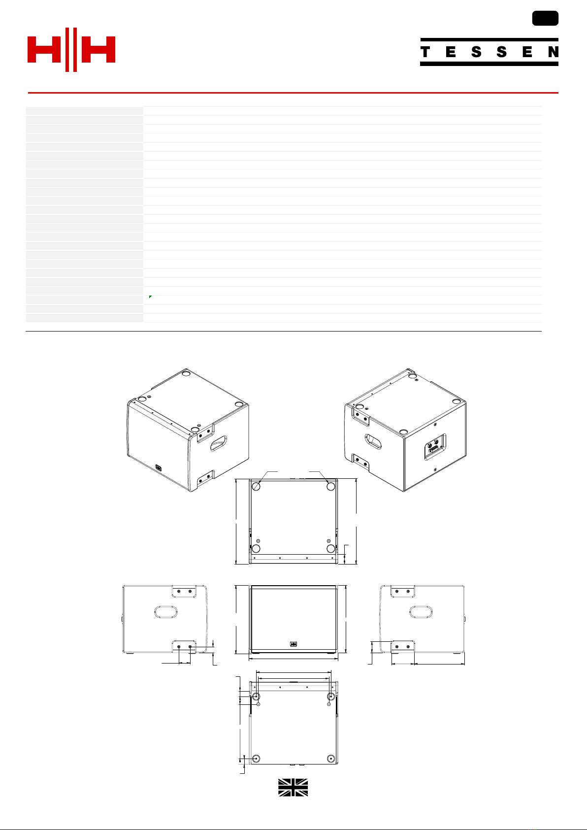
TNA-1200S-G2 - SPECIFICATIONS
11
1 AES standard Pink Noise 12dB crest factor 2 hours
2 Measured in Full space (4π) conditions
3 Calculated maximum SPL based on rated power handling
FREN
EN
475
366
OVER
FEET
360
120
60 269
454
457.3
OVER
SOCKETS
Ø 42
52
STACKING
REBATES
377
400
332
40
71
60 32
(Dimensions in mm)
Model TNA-1200S-G2
System type 12" Passive Subwoofer, Bass Reflex
Woofer Size 12" HH Designed High Performance Driver, 2.5" Voice Coil
Nominal System Impedance 8 ohm
Power Rating 300W AES, 600W Continuous, 1200W Peak
Recommended Amplifier 600-1200W @ 4 Ohms
Sensitivity 1W/1m 95 dB SPL
Maximum SPL (1m) 126 dB SPL, 132 dB SPL (Peak)
Frequency response 39 - 200Hz (-10dB)
47 - 120Hz (-3dB)
Input Connector NL4 ±1 Twist Lock Connector and M4 Barrier Strip Terminal (10mm Pitch)
Link Connector NL4 ±1 Twist Lock Connector and M4 Barrier Strip Terminal (10mm Pitch)
Enclosure
Main Construction Material Robust all wood construction (15mm plywood)
Finish Hard wearing black spatter finish
Grille Powdercoated steel with acoustic foam backing
Mounting Points 14x M8 fixings for optional TNA-BRK1 flying bracket assembly, TNA-DF1 Dolly Frame or TNA-2051 cabinets
Included Hardware 2x metal side brackets included
Unit dimensions (HWD) 366 x 475 x 454mm, 14.4" x 18.7" x 17.9"
Unit weight 16.2Kg, 35.7 lbs
Carton dimensions (HWD) 490 x 600 x 585mm, 19.3" x 23.6" x 23" , 0.172 M3
Packed weight 21Kg, 46.3 lbs
EAN Code 5060109457810
In the interest of continued development, HH reserves the right to amend product specification without prior notification.
Designed and Engineered in the UK by HH Electronics LTD.
© 2022 HH Electronics Ltd
LINE ARRAY LIVE SOUND & INSTALLATION
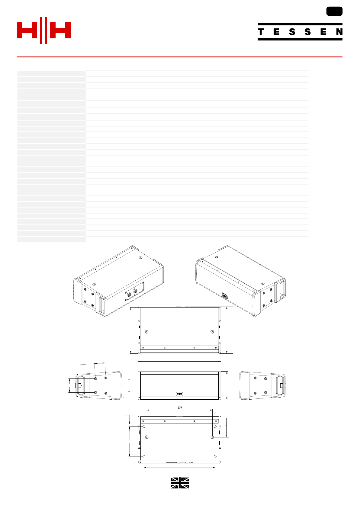
TNA-2051 - SPECIFICATIONS
(Dimensions in mm)
162.5
60
79.6 88
170
410
16.4
76.5
475
265.2 268.5
12
In the interest of continued development,
HH reserves the right to amend product
specification without prior notification.
Model TNA-2051
System type 2-way line array loudspeaker
Frequency Response 65Hz - 20KHz (-10dB)
100Hz - 18KHz (-3dB)
System Power Rating1200W AES, 800W Peak
SPL 1W/1m294 dB SPL
Max SPL 1m3123 dB SPL
System Max SPL 1m4132 dB SPL
Nominal System Impedance 16 ohms
Input Connector NL4 ±1 Twist Lock Connector
Link Connector NL4 ±1 Twist Lock Connector
Speaker
HF Driver 1 x 1.33'' Celestion Compression Driver, mounted to Celestion Designed waveguide and horn
LF Driver 2 x 5'' HH designed driver
Internal Crossover Frequency 2000Hz
Nominal dispersion 120° x 60° (120° x 30° single point)
Rigging/Splay Angle Settings Dual Angle, 0° and 8°
Recommended HPF Frequency 100Hz
Enclosure
Cabinet 15mm Plywood
Finish Painted Black (White finish optional, subject to MOQ)
Mounting Bracket TNA-BRK1 for suspended mounting
Mounting Points M8 side mounting for included brackets
Grille 1.5mm Thickness, Hexagonal mesh
Unit dimensions (HWD) 158 x 460 x 265mm, 6.2" x 18.1" x 10.4"
Unit weight 8.4Kg, 18.5 lbs (each)
Carton dimensions (HWD) 410 x 330 x 530mm, 16.1" x 13" x 20.9"
Packed weight 18.4Kg, 40.6 lbs (2pcs per carton)
4 System Max SPL based on 4x TNA-2051
1 AES standard Pink Noise 12dB crest factor 2 hours
2 Measured in Full space (4π) conditions
3 Calculated maximum SPL based on rated power handling
FREN
EN

© 2022 HH Electronics Ltd
LINE ARRAY
Designed and Engineered in the UK by HH Electronics LTD.
LIVE SOUND & INSTALLATION
CONSIGNES DE SÉCURITÉ IMPORTANTES
CAUTION:
WARNING:
12. Lors de l'utilisation sur pied ou perche de support, assurez dans le cas de déplacement de l'ensemble enceinte/support de prévenir tout
basculement intempestif de celui-ci.
4. Suivez ces instructions.
7. N'obstruez pas les systèmes de refroidissement de votre appareil et installez votre appareil en fonction des instructions de ce manuel.
2. Gardez ce manuel pour de futures références.
6. N'utilisez qu'un tissu sec pour le nettoyage de votre appareil.
5. N'utilisez pas cet appareil à proximité de plans d'eau.
ATTENTION: L'utilisation de tout appareil électrique doit être soumise aux précautions d'usage incluant:
1. Lisez ces instructions
3. Prêtez attention aux messages de précautions de ce manuel.
8. Ne positionnez pas votre appareil à proximité de toute source de chaleur.
9. Un appareil avec la construction de la classe I sera relié à une prise munie d'une liaison à la terre. Branchez toujours votre appareil sur une
alimentation munie de prise de terre utilisant le cordon d'alimentation fourni.
10. Protégez les connecteurs de votre appareil et positionnez les câblages pour éviter toutes déconnexions accidentelles.
11. N'utilisez que des fixations approuvées par le fabriquant.
14. Seul un technicien agréé par le fabriquant est à même de réparer/contrôler votre appareil. Celui-ci doit être contrôlé s'il a subi des dommages
de manipulation, d'utilisation ou de stockage (humidité, …).
17. Note pour le Royaume-Uni : Si les couleurs des fils du câble d'alimentation ne correspondent pas aux fiches de la prise secteur, procédez
comme suit:
a) Le fil vert et jaune doit être branché sur la borne repérée par la lettre E, ou le symbole de terre, ou par les couleurs vert ou verte et jaune.
b) Le fil bleu doit être branché sur la borne repérée par la lettre N, ou par la couleur noire.
c) Le fil marron doit être branché sur la borne repérée par la lettre L, ou par la couleur rouge.
19. Une exposition à de hauts niveaux sonores peut entraîner des dommages irréversibles de l'audition. La
sensibilité au bruit varie considérablement d'un individu à l'autre, mais la majorité de la population ressentira
une perte d'audition après une exposition à une forte puissance sonore pendant une durée prolongée.
15. Ne déconnectez jamais la prise de terre de votre appareil.
L'organisme de la santé américaine (OSHA) a produit le guide ci-dessous en rapport à l'exposition
autorisée aux niveaux de bruit:
20. Symboles utilisés sur les produits et dans les manuels des produits, destinés à alerter l'opérateur des zones ou des précautions supplémentaires
pouvant être nécessaires:
16. Si votre appareil est destiné à être monté en rack, des supports arrière doivent être utilisés.
18. Cet équipement électrique ne doit en aucun cas être en contact avec un quelconque liquide et aucun objet
contenant un liquide, tels qu'un vase ou autre récipient.
13. La fiche secteur est utilisée pour couper l'alimentation de l'appareil et doit rester facilement accessible. Débranchez cet appareil pendant les
orages ou s'il est inutilisé pendant de longues périodes.
Ce symbole est utilisé pour prévenir l'utilisateur de la présence d'instructions d'utilisation et de maintenance dans le mode d'emploi
accompagnant l'appareil.
Risque de choc électrique – NE PAS OUVRIR Afin de réduire les risque de choc électrique, ne pas ouvrir le capot. Il n'y a aucune pièce à
l'intérieur pouvant être réparée par l'utilisateur. Veuillez confier la maintenance à un personnel qualifié.
Afin de prévenir tout risque de choc électrique et d'incendie, n'exposez pas cet appareil à la pluie ou à l'humidité. Avant d'utiliser cet
appareil, lisez attentivement les instructions d'utilisation de ce mode d'emploi.
D'après les études menées par l'OSHA, toute exposition au delà des limites décrites ci-dessous entraînera des
pertes de audition chez la plupart des sujets. Le port de système de protection (casque, oreillette de filtrage,
etc…) doit être observé lors de l'utilisation de cet appareil sans quoi des dommages irréversibles peuvent
être occasionnés. Le port de ces systèmes doit être observé par toutes personnes susceptibles d'être exposées à des conditions au delà des
limites décrites ci-dessous.
Ce symbole est utilisé pour prévenir l'utilisateur de la présence d'une tension non isolée dangereuse à l'intérieur du boîtier de l'appareil, et pouvant être
suffisante pour constituer un risque de choc électrique.
Si votre appareil est équipé d'un mécanisme de basculement ou si son boîtier est conçu comme retour, veuillez utiliser cette caractéristique avec
prudence. En raison de la facilité avec laquelle l'amplificateur peut être basculé entre les positions droite et inclinée, utilisez uniquement
l'amplificateur sur une surface plane et stable. NE PAS faire fonctionner l'amplificateur sur un bureau, une table, une étagère ou autre plate-forme
inappropriée.
FREN
FR
13

Designed and Engineered in the UK by HH Electronics LTD.
© 2022 HH Electronics Ltd
LINE ARRAY LIVE SOUND & INSTALLATION
TNA-1200S-G2 AND TNA-2051 – PANNEAU ARRIÈRE
Outre les enceintes TNA, des accessoires de qualité supérieure sont proposés. Le support de fixation en acier massif TNA-BRK1
assure une suspension sûre du système TNA lorsqu'il est installé. Le cadre du chariot à roues TNA-DF1 se fixe auTNA-1200S-G2
assurant le transport flexible d'un système complet.
TNA mini line array - la solution audio ou fixe parfaite.mobile
Avec la demande croissante d'applications de son en direct, les utilisateurs demandent plus de leur système audio. Le mini line array
TNA fournit un rendement élevé dans un système compact. Adapté soit comme système de sonorisation en installation fixe , soit
pour une utilisation portable, le mini line array TNA offre une dynamique cristalline.
La gamme TNA comprend la TNA-2051; Enceinte line array passive bidirectionnelle équipée de deux HP 5'' et d'un moteur à
compression spécialement réalisé par Celestion, et le TNA-1200S-G2; d'un HP sub passif haute performance de 12 ”.
14
TNA-1200S-G2
TNA-2051
WIRING
± 1 INPUT
± 2 N/A
INPUT LINK
DESIGNED AND ENGINEERED
IN THE UK BY
WWW.HHELECTRONICS.COM SN:ABC1234567890
MODEL: TNA-2051
WIRING
± 1 INPUT
± 2 N/A
INPUT LINK
DESIGNED AND ENGINEERED
IN THE UK BY
WWW.HHELECTRONICS.COM
MADE IN CHINA
+
-
+
-
IMPEDANCE
POWER AES
CONTINUOUS
POWER PEAK
8Ω
300W
600W
1200W
SN:ABC1234567890
MODEL: TNA-1200S-G2
3 :BORNIER A VIS M4 : Fournis pour une flexibilité de câblage supplémentaire. Ceux-ci sont connectés en interne aux
connecteurs NL4 comme on peut le voir dans le schéma ci-dessous.
1 : ENTRÉE : À connecter à la sortie de l'amplificateur choisi. Vérifiez les spécifications techniques de votre amplificateur pour vous
assurer que son impédance et sa puissance de sortie conviennent à une utilisation avec une enceinte TNA-1200S-G2.
Comme pour le TNA-1800S-G2, le TNA-1200S-G2 et le TNA-2051 sont équipés de connecteurs à verrouillage par ¼ de tour NL4
±1, ainsi que des borniers à vis M4 supplémentaires sur le TNA-1200S-G2.
2 : LINK : Connectée en parallèle avec le connecteur INPUT, cette prise permet d'ajouter des enceintes supplémentaires à la chaîne
d'enceintes.
DIAGRAMME SYSTÈME:
NE PAS CONNECTER UN DEUXIÈME AMPLIFICATEUR À LA SORTIE LINK OU AUX BORNIERS !
FREN
FR
3
1
1
2
2
INTRODUCTION
DRIVERS
HF
LF
LF
1
11
+
++
2+
2+2+
LINK
2+
2+2+
1+
1+1+
INPUT
++
+
X-OVER
1
11
1
11
2
22
2
22
(LINK)
(INPUT)
LF DRIVER
1+
1+1+
2+
2+2+
LINK
1
11
2
22
2+
2+2+
1+
1+1+
INPUT
1
11
2
22
+
++
+
++
+
++
+
++

© 2022 HH Electronics Ltd
LINE ARRAY
Designed and Engineered in the UK by HH Electronics LTD.
LIVE SOUND & INSTALLATION
Le support latéral TNA est utilisé pour assurer la fixation / le support mécanique entre le sub TNA-1200S-G2 et les satellites
TNA-2051. Selon la combinaison de trous utilisée, une disposition verticale ou angulaire peut être obtenue.
Les options d'ajustement sont imprimées
sur le support latéral.
Dans tous les cas, l'encoche
d'emplacement doit pointer
vers la face avant de l'enceinte.
15
FREN
FR
1+2
3+4
1+4
1+2

Designed and Engineered in the UK by HH Electronics LTD.
© 2022 HH Electronics Ltd
LINE ARRAY LIVE SOUND & INSTALLATION
CONTENU
SUPPORT DE FIXATION POUR TNA-1200S-G2
Le support de fixation TNA-BRK1 à utiliser avec le TNA-1200S-G2 et le
TNA-2051. Grâce à sa construction en acier solide, le TNA-BRK1 supporte en toute
sécurité jusqu'à deux sub TNA-1200S-G2 et quatre TNA-2051 simultanément.
Le TNA-BRK1 est fixé au TNA-1200S-G2 à l'aide de deux supports latéraux et d'un
support arrière.
Comme pour le TNA-1200S-G2, les rondelles
doivent être utilisées avec toutes les vis!
Des rondelles doivent être utilisées avec chaque vis!
Faites très attention de ne pas croiser les vis latérales lors du montage des supports!
TNA-BRK1 - FLYING BRACKET
LOCKNUT
SPRING WASHER
SPRING WASHER
REAR BRACKET
LOCKNUT
SPRING WASHER
SIDE BRACKET
1 x Lift Bracket assembly
3 x D-shackle
2 x Side plate
1 x Rear plate
7 x M8x25mm connector bolt
6 x M8 lock nuts
7 x Spring washers
LOCKNUT
SPRING WASHER
SIDE BRACKET
SPRING WASHER
SUPPORT DE FIXATION POUR TNA-2051
Un TNA-2051 nécessite l'utilisation de supports latéraux uniquement.
SPRING WASHER
16
FREN
FR
© 2022 HH Electronics Ltd
LINE ARRAY
Designed and Engineered in the UK by HH Electronics LTD.
LIVE SOUND & INSTALLATION
SÉCURITÉ
W
D
H
Selon les réglementations locales, des supports de traction supplémentaires peuvent être nécessaires.
N'essayez en aucun cas de gréer, suspendre ou monter ce système de quelque manière que ce soit, sauf si vous êtes pleinement
qualifié et certifié pour le faire par les autorités locales, étatiques et nationales compétentes. Toutes les règles de sécurité pertinentes
doivent être respectées. Si vous n'êtes pas correctement qualifié ou si vous ne connaissez pas les réglementations pertinentes,
consultez un personnel qualifié pour obtenir des conseils et une assistance.
La fixation des enceintes ne doit être effectué que par des personnes correctement qualifiées, conformément à toutes les lois locales
et en utilisant du matériel approuvé.
Il est de la responsabilité de l'installateur de s'assurer que le point de fixation est structurellement adéquat pour supporter le poids
des enceintes.
Le gréement ou le montage suspendu de ces enceintes peut exposer les membres du public à des accidents graves voir mortels.
Pour plus de sécurité, il est fortement recommandé de vérifier périodiquement les connexions audio, les fixations mécaniques et les
supports de montage.
DEUX TNA-1200S-G2
JUSQU'À HUIT TNA-2051*
CARACTÉRISTIQUES
LIMITE DE SOUTIEN MAXIMALE TNA-BRK1
17
FREN
FR
Model
TNA-BRK1
Suspension Type
The bracket allows you to fit upto three D-shackles (included)
Mounting Type
Five M8 mounting points hold the bracket securely to the cabinet
Max Load Weight
120Kg, 264lbs
Max Unit Load
8x TNA-2051 & 2x TNA-1200S-G2 OR 4x TNA-1200S-G2
Unit dimensions (HWD)
64 x 451 x 340mm, 2.5" x 17.8" x 13.4"
Unit weight
5.6Kg, 12.3 lbs
Carton dimensions (HWD)
145 x 505 x 430mm, 5.7" x 19.9" x 16.9" , 0.031 M3
Packed weight
6.7Kg, 14.8 lbs
In the interest of continued development, HH reserves the right to amend product specification without prior notification.
*support de retrait supplémentaire requis pour plus de 4 TNA-2051

Designed and Engineered in the UK by HH Electronics LTD.
© 2022 HH Electronics Ltd
LINE ARRAY LIVE SOUND & INSTALLATION
Avec sa conception légère et robuste, le TNA-DF1 permet aux enceintes d'être facilement repositionnées et configurées pour
répondre aux besoins actuels.
VEUILLEZ NOTER: Un maximum de quatre TNA-2051 et deux TNA-1200-G2 doivent être utilisés sur le chariot.
TNA-DF1 - CHARIOT
TNA-DF1 (à l'aide de deux supports
latéraux et d'un support arrière) avec
six boulons hexagonaux M8 x 20.
Le TNA-1200S-G2 est fixé au Assurez-vous que les freins sont engagés
sur les roues arrière une fois que le Line
Array a été correctement positionné.
18
FREN
FR
© 2022 HH Electronics Ltd
LINE ARRAY
Designed and Engineered in the UK by HH Electronics LTD.
LIVE SOUND & INSTALLATION
WICHTIGE SICHERHEITSHINWEISE
CAUTION:
WARNING:
11. Verwenden Sie nur die vom Hersteller erhältlichen Zubehörgeräte oder Zubehörteile.
6. Reinigen Sie es nur mit einem trockenen Tuch.
9. Verwenden Sie nur Kaltgeräte-Netzkabel aus dem Fachhandel.
3. Beachten Sie alle Warnungen.
10. Schützen Sie das Netzkabel, sodass niemand darauf tritt oder es geknickt wird, insbesondere an Steckern oder Buchsen am Gerät.
1. Lesen Sie sich diese Anweisungen durch.
5. Setzen Sie dieses Gerät nicht in der Nähe von Wasser ein.
2. Bewahren Sie diese Anweisungen auf.
Sollen den Benutzer auf das Vorhandensein von "gefährlicher Hoch- Spannung" im Gerätegehäuse hinweisen, um die Gefahr eines elektrischen
Schlages für Personen zu vermeiden..
Sollen den Benutzer auf das Vorhandensein wichtiger Betriebs-und Wartungsanweisungen in der begelegten Dokumentation
aufmerksam machen.
Gefahr eines elektrischen Schlags - NICHT ÖFFNEN. Um die Gefahr eines elektrischen Schlags zu reduzieren, darf die Abdeckung
entfernen. Keine zu wartenden Teile im Inneren. Überlassen Sie die Wartung qualifiziertem Fachpersonal.
18. Dieses Gerät darf nicht ungeschützt Wassertropfen und Wasserspritzern ausgesetzt werden und es muss
darauf geachtet werden, dass keine mit Flüssigkeiten gefüllte Gegenstände, wie z. B. Blumenvasen, auf dem
Gerät abgestellt werden.
12. Verwenden Sie nur einen Wagen, Stativ, Dreifuß, Träger oder Tisch, der den Angaben des Herstellers entspricht oder zusammen mit dem Gerät
verkauft wurde. Wird ein Wagen verwendet, bewegen Sie den Wagen mit dem darauf befindlichen Gerät besonders vorsichtig, damit es nicht
umkippt und möglicherweise jemand verletzt wird.
4. Befolgen Sie alle Anweisungen.
13. Der Netzstecker bzw. Gerätestecker wird zum Trennen vom Stromnetz verwendet und muß immer leicht zugänglich sein.
ACHTUNG: Beim Einsatz von Elektrogeräten müssen u.a. grundlegende Vorsichtsmaßnahmen befolgt werden:
7. Blockieren Sie keine der Lüftungsöffnungen. Führen Sie die Installation gemäß den Anweisungen des Herstellers durch.
8. Betreiben Sie das Gerät nicht neben Wärmequellen wie Heizungen, Heizgeräten, Öfen oder anderen Geräten (auch Verstärkern), die Wärme
erzeugen.
Der Benutzer sollte auf einfachen Zugang zu allen Netzsteckern,Gerätesteckern und Netz-Schaltern achten
Ziehen Sie den Netzstecker bei Gewitter heraus oder wenn das Gerät längere Zeit nicht benutzt wird.
15. Schließen Sie das Gerät nur an eine Stromquelle an, die am Gerät neben dem Netzkabel angegeben ist.
19. Belastung durch extrem hohe Lärmpegel kann zu dauerhaftem Gehörverlust führen. Die Anfälligkeit für
durch Lärm bedingten Gehörverlust ist von Mensch zu Mensch verschieden, das Gehör wird jedoch bei jedem
in gewissem Maße geschädigt, der über einen bestimmten Zeitraum ausreichend starkem Lärm ausgesetzt ist.
Die US-Arbeitsschutzbehörde (Occupational and Health Administration, OSHA) hat die folgenden zulässigen
Pegel für Lärmbelastung festgelegt:
14. Lassen Sie sämtliche Wartungsarbeiten von qualifizierten Kundendiensttechnikern durchführen. Eine Wartung ist erforderlich, wenn das Gerät in
irgendeiner Art beschädigt wurde, etwa wenn das Netzkabel oder der Netzstecker beschädigt wurden, Flüssigkeit oder Gegenstände in das Gerät
gelangt sind, das Gerät Regen oder Feuchtigkeit ausgesetzt wurde, nicht normal arbeitet oder heruntergefallen ist.
16. Wenn dieses Produkt in ein Geräte-Rack eingebaut werden soll, muss eine Versorgung über die Rückseite
eingerichtet werden.
Laut OSHA kann jede Belastung über den obenstehenden zulässigen Grenzwerten zu einem gewissen
Gehörverlust führen. Sollte die Belastung die obenstehenden Grenzwerte übersteigen, müssen beim Betrieb dieses Verstärkungssystems
Ohrenstopfen oder Schutzvorrichtungen im Gehörgang oder über den Ohren getragen werden, um einen dauerhaften Gehörverlust zu verhindern.
Um sich vor einer möglicherweise gefährlichen Belastung durch hohe Schalldruckpegel zu schützen, wird allen Personen empfohlen, die mit Geräten
arbeiten, die wie dieses Verstärkungssystem hohe Schalldruckpegel erzeugen können, beim Betrieb dieses Geräts einen Gehörschutz zu tragen.
20. Symbole und Nomenklatur, die auf dem Produkt und in den Handbüchern stehen, sollen den Bediener auf die Bereiche, in denen besondere
Vorsicht notwendig sein kann, alarmieren und sind wie folgt:
Gefahr eines elektrischen Schlags - NICHT ÖFFNEN. Um die Gefahr eines elektrischen Schlags zu vermeiden, darf die Abdeckung
nicht geöffnet werden.. Überlassen Sie die Wartung qualifiziertem Fachpersonal.
Wenn Ihr Gerät über einen Kippmechanismus oder eine “Tilt-back“- Funktion verfügt, beutzen Sie diese Funktion mit Vorsicht. Aufgrund der
Leichtigkeit, mit der der Verstärker zwischen geraden und schrägen Rücken Positionen bewegt werden kann, verwenden Sie nur den Verstärker auf
einer ebenen, stabilen Oberfläche. NICHT den Verstärker auf einem Schreibtisch, Tisch, Regal oder sonst eine ungeeignete nicht stabile Plattform
stellen.
EN
DE
19

Designed and Engineered in the UK by HH Electronics LTD.
© 2022 HH Electronics Ltd
LINE ARRAY LIVE SOUND & INSTALLATION
EINLEITUNG
Da Live-Sound-Anwendungen immer mehr nachgefragt werden, erwarten Anwender mehr von ihrem Audiosystem. Das TNA Mini
Line Array bietet eine hohe Leistung in einem kompakten System. Das TNA Mini Line Array eignet sich entweder als fest installiertes
Soundsystem oder für den tragbaren Einsatz und liefert eine kristallklare Dynamik.
Das TNA-Sortiment umfasst TNA-2051; Dual 5" Zwei-Wege-Passiv-Line-Array-Lautsprecher mit maßgeschneidertem Celestion-
Komprimierungstreiber und Wellenführung und dem TNA-1200S-G2; 12" Hochleistungs-Passivsubwoofer.
Die TNA-BRK1-Stahlhalterung sorgt bei der Installation für eine sichere Aufhängung des TNA-Systems. Der TNA-DF1 Rad-Dolly-
Rahmen wird an der TNA-1200S-G2 befestigt und bietet flexiblen Transport eines gestapelten Systems.
TNA Mini-Line-Array – die perfekte mobile oder installierte Audio-Lösung.
TNA-1200S-G2 AND TNA-2051 – RÜCKSEITE
20
TNA-1200S-G2
SYSTEMDIAGRAMM
Wie beim TNA-1800S-G2 verfügen sowohl der TNA-1200S-G2 als auch der TNA-2051 über NL4 ±1 Kombi-Eingänge mit
zusätzlichen M4-Anschlussklemmen am TNA-1200S-G2.
Überprüfen Sie die technischen Daten Ihres Verstärkers, um sicherzustellen, dass seine Treiberfähigkeit und Ausgangsleistung für die
Verwendung eines TNA-1200S-G2 geeignet ist.
1: INPUT: Zum Anschluss an den Ausgang des von Ihnen gewählten Verstärkers.
2: LINK: Parallel mit dem INPUT-Anschluss verbunden, sodass zusätzliche Boxen hinzugefügt werden können.
SCHLIESSEN SIE KEINEN ZWEITEN VERSTÄRKER AN DEN LINK-AUSGANG ODER DIE M4-ANSCHLÜSSE AN!
3: M4-ANSCHLUSSSTECKVERBINDER: Für zusätzliche Verdrahtungsflexibilität. Diese sind intern mit den NL4-Anschlüssen
verbunden, wie im Diagramm unten zu sehen.
TNA-2051
WIRING
± 1 INPUT
± 2 N/A
INPUT LINK
DESIGNED AND ENGINEERED
IN THE UK BY
WWW.HHELECTRONICS.COM SN:ABC1234567890
MODEL: TNA-2051
WIRING
± 1 INPUT
± 2 N/A
INPUT LINK
DESIGNED AND ENGINEERED
IN THE UK BY
WWW.HHELECTRONICS.COM
MADE IN CHINA
+
-
+
-
IMPEDANCE
POWER AES
CONTINUOUS
POWER PEAK
8Ω
300W
600W
1200W
SN:ABC1234567890
MODEL: TNA-1200S-G2
EN
DE
3
1
1
2
2
DRIVERS
HF
LF
LF
1
11
+
++
2+
2+2+
LINK
2+
2+2+
1+
1+1+
INPUT
++
+
X-OVER
1
11
1
11
2
22
2
22
(LINK)
(INPUT)
LF DRIVER
1+
1+1+
2+
2+2+
LINK
1
11
2
22
2+
2+2+
1+
1+1+
INPUT
1
11
2
22
+
++
+
++
+
++
+
++
This manual suits for next models
1
Other HH Electronics Speakers manuals

HH Electronics
HH Electronics MZ Series User manual

HH Electronics
HH Electronics TESSEN TNi-W8PRO User manual

HH Electronics
HH Electronics Tensor TRE-1001 User manual

HH Electronics
HH Electronics Tessen TNi-W4 User manual

HH Electronics
HH Electronics Tessen TNi-W4 User manual

HH Electronics
HH Electronics Tensor TRM-1201 User manual

HH Electronics
HH Electronics Tensor-SOLO User manual

HH Electronics
HH Electronics VECTOR VRE-12 User manual


