HHO Plus CCPWM60A User manual

CCPWM60A – Installation Manual
HHO Hydrogen on Demand Dual Fuel Generator Systems

CCPWM60A – Installation Manual 2
CONTENTS
Disclaimer 3
Safety Precautions 3
Parts List 3
Technical Specifications 4
Pulse Width modulation 5
Main Features of the CCPWM60A 5
Electric Connections 6
Front Panel 7
Setting the operating values 8
Electrolyte and Amperage Control 9
Water Level Sensor 10

CCPWM60A – Installation Manual 3
Disclaimer
When purchasing this device, you are held responsible for any damage that may occur during installation or
operation of this device. The manufacturer or seller are not held liable and hold no responsibility for any
personal harm or property damage. Thank you for purchasing our CCPWM60A Constant Current Automatic
Power Device. Please read contents carefully in order to understand the installing and operation procedures
before getting started.
Safety Precautions
Read and follow these safety precautions to avoid hazards. If you do not understand these instructions or do
not like to work on vehicles, please have a qualified mechanic do the installation for you. Incorrectly installing
or using the CCPWM60A and/or the HHO System may result in serious damage to you and/or your vehicle.
It should take approximately half an hour to install this unit, so ensure that you have enough time to complete
the installation. Be sure to work outside, no smoking at any time during the installation; make sure the engine
is off and very importantly, not hot.
Your HHO System do not store hydrogen, subsequently there is no fire hazard when installed properly.
However water electrolysis generates Hydrogen, an explosive gas, which means that you should never light a
match or smoke near or in front of the generators output - the water tank could blow up!
Be careful with the generator working when the car is not moving. A small amount of hydrogen can
accumulate in the air intake of the motor and could explode if you smoke or use an open flame near it.
Be sure to wear goggles and rubber gloves and only use professional tools; use common sense and general
safety procedures used for any work carried out on automotive installations and maintenance.
Parts List
The CCPWM60A package includes the following items:
• 1 CCPWM60A Constant Current Automatic Power Switch Detection;
• 3 Yellow Butt Connectors.
CCPWM60A – Installation Manual 4
Technical Specifications
• Direct connection from Battery and Input to HHO CELL generator, without external relays;
• 60A Max Power supply;
• LCD Module Monochrome Display Screen: Voltmeter + Ammeter + Cell Charge information;
• Automatic detection of battery voltage and auto configuration for: +12V/+24V power supply;
• Quad operational chip sensor with 1% tolerance Zenner voltage detector;
• Auto power ON when the Engine is running;
• 3 Seconds delay PWM control, after Engine ON is detected;
• Auto Power OFF when Engine is turned OFF;
• Soft PWM startup to the max Ampere out power supply;
• Embedded trimmer for PWM control: from 0% to 100% HHO CELL power supply;
• Logical IC sensor, MUST be powered with 2 wires DIRECT from the battery;
• Embedded 4 way power barrier: Positive, Gnd, CELL - OUT, CELL + OUT;
• Optional Water tank sensor switch embedded on system;
• 2 Compact Alluminium dissipators for the 60A Mosfet;
• Frequency: 36kHz

CCPWM60A – Installation Manual 5
Pulse Width modulation
Pulse Width Modulation is a method of transmitting information on a series of pulses, changing the
frequency, rather than a continuously varying analog signal. It will allow you to control the amperage going
into the generator in a very easy way. This ability keeps the cell running at cool operating temperatures and
prolongs the life of the cell while increasing the HHO output
Efficiency: HHO generators will run cooler than standard linear power amps, requiring substantially less heat
sink mass;
Amperage control: the control of the amperage going into the generator will be very easy to control. The
ability to control the amperage keeps the cell running at cool operating temperatures and prolongs the life of
the cell while increasing the HHO output.
Main Features of the CCPWM60A
NEW TECHNOLOGY: The CCPWM60A (Constant Current Pulse Width Modulator) will allow you to have always
the same amperage and HHO production regardless the electrolyte concentration, water temperature or
water levels. The CCPWM is the best solution for the professional market because there will be no possibility
of error. We can put more or less electrolyte and the amperage and HHO production will always be the same.
The CCPWM60A is also designed for making the automatic power supply of the HHO System without the need
for relays or picking up the signal from the alternator/ignition key, making the system safer to use and easier
to install. In general the new CCPWM60A will work based on the voltage of the car/truck:
- Engine is stoped – voltage in car/truck is 12V or 24V – PWM is not working;
- Engine is working – voltage in car/truck is 13,8V or 27,6V – PWM is working.
The CCPWM60A autodetect when the car engine is running and automatically switches ON the HHO System,
without any additional requirements. The device will automatically power OFF when the car engine is turned
OFF or not running.
The CCPWM is also capable to control a water level sensor inserted in the water tank turning the system OFF
when the level drops from a certain point.
Important: This product is intended for use on an automobile/truck with 12/24V
battery operation only. Working this devise with an independent power supplies
may result in malfunction and/or damage the devise.

CCPWM60A – Installation Manual 6
Electric Connections
1. Make sure your engine is not running during installation;
2. Mount the product as near of the battery as possible (maximum 3 meters), providing that it is well
fixed. Please do not mount it over the battery;
3. Connect the black cable to the negative terminal of the battery;
4. Connect the red cable to the positive terminal of the battery;
5. Connect the blue cable to the negative coming from the HHO Cell;
6. Only use 4 mm section cable in your installation. Use the Yellow Butt Connectors.
Please refer to the illustration below for typical configuration of the electrical connections of the CCPWM30A:
CCPWM60A – Installation Manual 7
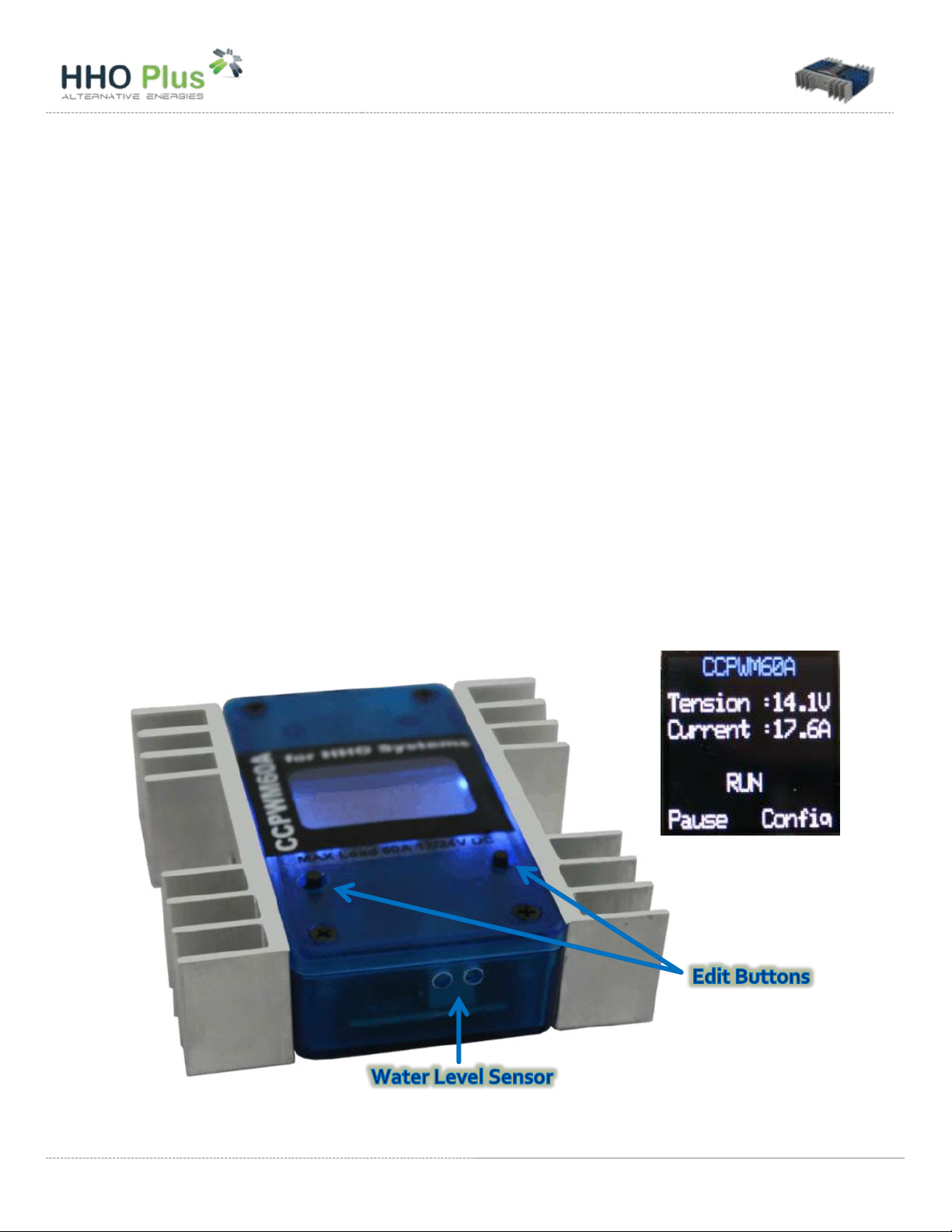
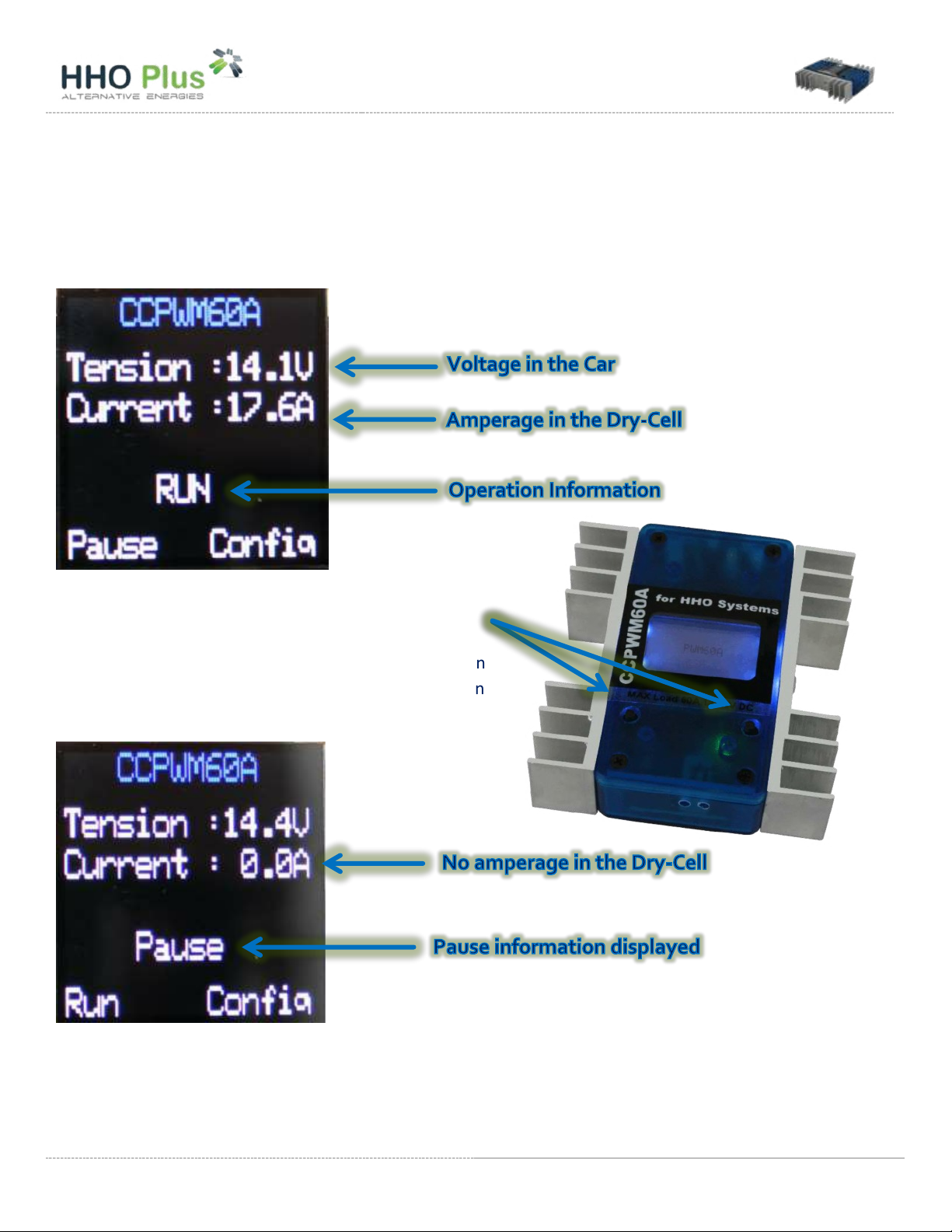
Front Panel
When you connect the CCPWM60A you will find the following information displayed:
In the CCPWM you have two buttons that will allow you
to change settings and control the device operation.
For example: if you press the left button (Pause) then
the CCPWM will pause and the following information
will be presented:
If you press the left button again (Run) then the CCPWM will start working again. The display panel will show
first “idle” and after “Run”.

CCPWM60A – Installation Manual 8
Setting the operating values
If you press the right button (Config) you will enter the configuration display where you can change the
operating values of the CCPWM:
The CCPWM will only work when the real car voltage value is between the minimum and the maximum
working voltage value. For example if we work with the values displayed above the result will be:
Car voltage 13,4V ---------> CCPWM will work
Car voltage 14,6 V --------> CCPWM will not work
Car voltage 12,7 V --------> CCPWM will not work
In the configuration panel you can select the feature to edit using the left button (V):
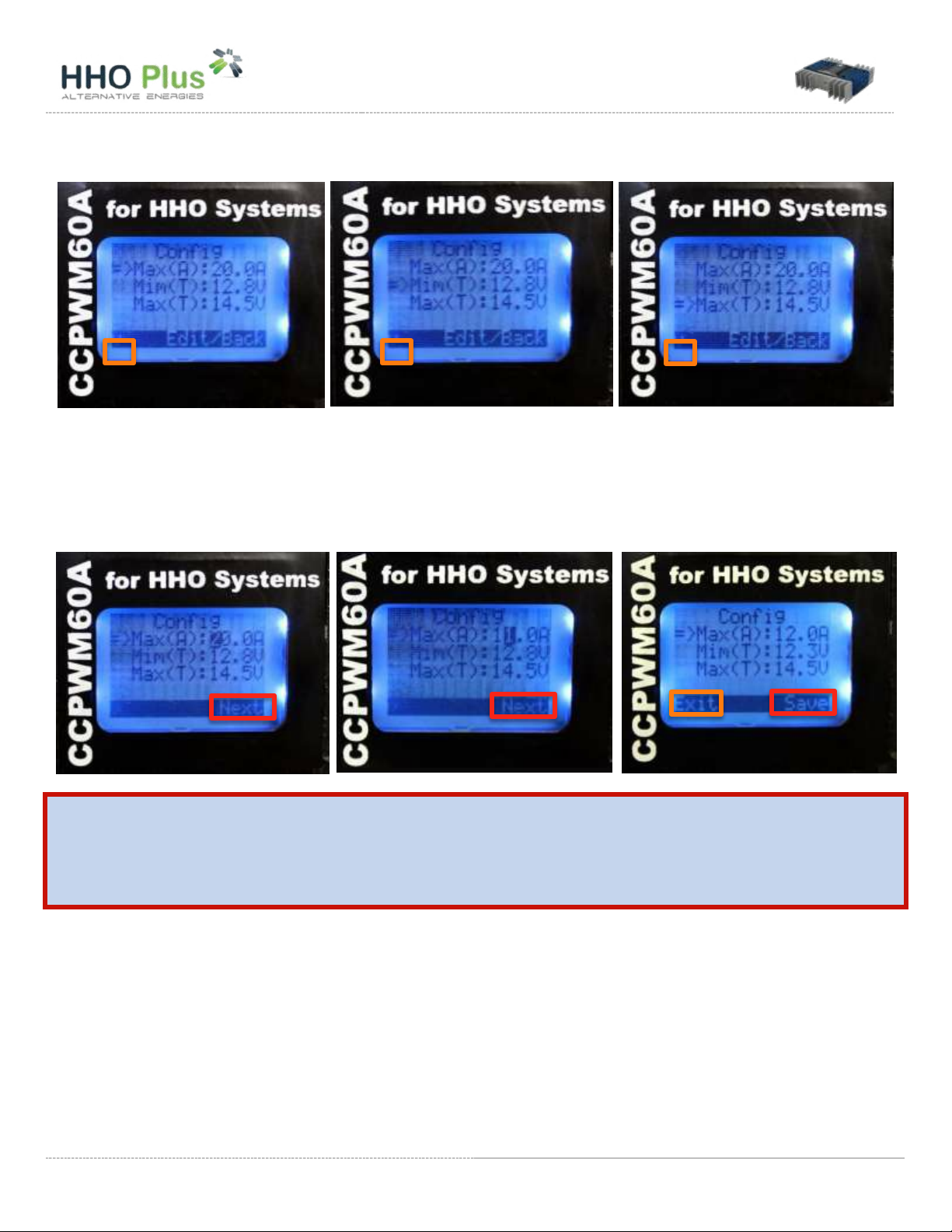
CCPWM60A – Installation Manual 9
Once selected the feature you want to change value you need to press the right button (Edit) for more than 2
seconds in order to start flashing the number to edit. Use right button (Next) to move cursor to new number
and after to save (Save) your settings. In the last panel if you press left button (Exit) you work will not be
saved.
IMPORTANT: After having selected your voltage working limits you should test it
to check if it works correctly in your car. Stop engine and check if the CCPWM
shuts down. Start engine and check if CCPWM turns ON.
Electrolyte and Amperage Control
Electrolysis of water is the decomposition of water molecule (H2O) into oxygen (O2) and hydrogen (H2) gases
due to an electric current passing in the water. Electrolysis of pure water requires excess energy in the form of
potential to overcome various activation barriers. Without the excess energy the electrolysis of pure water
occurs very slowly or not at all. This is in part due to the limited self- ionization of water. The efficacy of
electrolysis is increased through the addition of an electrolyte (such as a salt, an acid or a base).
CCPWM60A – Installation Manual 10
The electrolyte should be added to the water the first time that you use the system, and also when refilling,
but in lower quantities. The more electrolyte you add to the water, the more amperage you will have in the
system and also more HHO gas will be produced. But, it is false to assume that a higher HHO gas production
will mean a higher fuel savings. There is an optimum point for all internal combustions engines. The
maximum amperage of the PWM will be set by the electrolyte concentration in the water. The PWM will
only control the amperage below this value.
Please use the following electrolyte concentration when using our CCPWM for the first time:
• 12V -> 20 grs KOH/liter
• 24V -> 10 grs KOH/liter
IMPORTANT: If the CCPWM turns ON and shuts down right after, and repeats this
continuously, then you are using too much electrolyte. Please remove the solution
and add a new one.
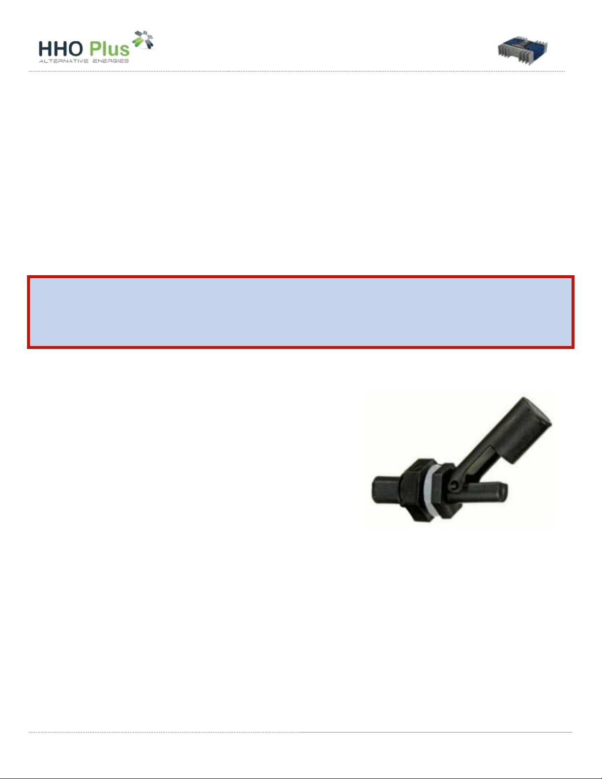
Water Level Sensor
The water level should be placed in a way that, when the water
level is above the minimum value, the signal coming from the
CCPWM does not return to the CCPWM. That is, the water level
circuit should operate as normally open (NO). Using our
company models, the water level sensor should be placed up
(please check last picture on this manual).
If you are not using a water level sensor in your system, no
operation is required.

Other manuals for CCPWM60A
3
Table of contents
Other HHO Plus Automobile Accessories manuals


Popular Automobile Accessories manuals by other brands


Paser
Paser UNICO DUAL PLUS installation manual

TEINHOF
TEINHOF V-072 FITTING AND OPERATION MANUAL

WABCO
WABCO 971 002 923 2 quick start guide

Conceptronic
Conceptronic CUSBCAR2AKIT quick guide

Donmar
Donmar SH-R-00 installation instructions

Metra Electronics
Metra Electronics 99-3410 installation instructions


