HHO Plus DC2000 User manual
DC2000 –Installation Manual
HHO Hydrogen on Demand Dual Fuel Generator Systems
HHO Plus, Alternative Energies, Ltd
Technical Department
Travessa das Serras 33, Vieira de Leiria, Portugal
T: 00 351 244 697 116 E: info@hhoplusgas.com

DC2000 –Installation Manual 2
HHO Plus, Alternative Energies, Lta –Travessa das Serras 33, Vieira de Leiria, Portugal –Tel. 00351244697116 –Email: [email protected]
CONTENTS
Safety Precautions 4
Important Information 4
Safety Equipment 4
Enjoy your new system 4
Installation of the hydraulic components 5
General configuration 5
Positioning the Dry-Cell 5
Positioning the Water Tank 8
Positioning the Bubbler 9
Positioning the water and HHO hoses 10
HHO injection point 11
Installation of the electrical components 13
General configuration 13
Battery 13
Identifying the ignition source 13
Dry-Cell electric connections 14
Water and electrolyte setup 16
Principles of the water electrolysis 16
Electrolyte concentration 16
Water levels in the tank 18
Amperage variation in the system 18
Electronic fuel injection 20
Basic Information 20

DC2000 –Installation Manual 3
HHO Plus, Alternative Energies, Lta –Travessa das Serras 33, Vieira de Leiria, Portugal –Tel. 00351244697116 –Email: [email protected]
Components of the electronic injection 21
MAP/MAF sensor 21
Lambda sensors 22
Resetting the ECU 23
Installing the lambda sensor extender –Pre-Cat Sensor 24
Isolating the lambda sensor body –Pre-Cat and Pos-Cat Sensors 26
Test run and checking your work 27
Maintenance 27
Check-list for HHO system debugging 28
Important information 28
Check-List 28
Parts positioning 30
HHO connection from the water tank to the bubbler 31
HHO connection from the bubbler to the air intake manifold 32
Water connections between the water tank and the dry-cell 33
Electric connection from the battery to the relay (Position 30) 34
Electric connection from the ignition source to the relay (Position 85) 35
Electric connection from the relay (Position 86) to the Ground 36
Electric connection from the relay (Position 87) to the dry cell 37
Electric connection from the dry cell to the ground 38

DC2000 –Installation Manual 4
HHO Plus, Alternative Energies, Lta –Travessa das Serras 33, Vieira de Leiria, Portugal –Tel. 00351244697116 –Email: [email protected]
Safety Precautions
Important Information
Read and follow these safety precautions to avoid hazards. If you do not understand these instructions or do
not like to work on vehicles, please have a qualified mechanic do the installation for you. Incorrectly installing
or using the HHO System may result in serious damage to you and/or your vehicle.
It should take approximately 3 hours to install this unit, so ensure that you have enough time to complete the
installation. Be sure to work outside, no smoking at any time during the installation; make sure the engine is
off and very importantly, not hot.
Your HHO System does not store hydrogen, subsequently there is no fire hazard when installed properly.
However water electrolysis generates Hydrogen, an explosive gas, which means that you should never light a
match or smoke near or in front of the generators output - the water tank could blow up!
Be careful with the generator working when the car is not moving. A small amount of hydrogen can
accumulate in the air intake of the motor and could explode if you smoke or use an open flame near it.
Safety Equipment
Be sure to wear goggles and rubber gloves and only use professional tools; use common sense and general
safety procedures used for any work carried out on automotive installations and maintenance.
Enjoy your new system
Be safe and enjoy your new Hydrogen on Demand Dual Fuel Generator System, read and understand these
instructions before and during the installation and you will benefit from your new system for years to come.
DC2000 –Installation Manual 5
HHO Plus, Alternative Energies, Lta –Travessa das Serras 33, Vieira de Leiria, Portugal –Tel. 00351244697116 –Email: [email protected]
Installation of the hydraulic components
General configuration
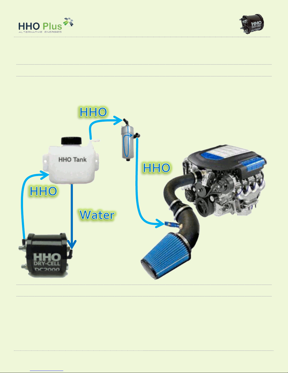
Please refer to the illustration below for typical configuration of the mechanical and hydraulic parts of the
HHO system. In the end pages of this manual you will be able to check each one of the individual connections
to be made regarding the installation of the components. We will now only focus on the main aspects of the
installation.
Positioning the Dry-Cell
You will need to find a good place in your engine compartment to mount your new HHO system. Please
remember that the water tank should preferably be placed at least 20 cm above the generator Dry-Cells in
order to guarantee a sufficient water head for the water/hydrogen to flow. But in some cases with not too
much space available to make the installation we just need to make sure that the bottom of the water tank is
a little bit higher than the top of the dry-cell.
Bubbler
Air Intake
Manifold
DC2000 –Installation Manual 6
HHO Plus, Alternative Energies, Lta –Travessa das Serras 33, Vieira de Leiria, Portugal –Tel. 00351244697116 –Email: [email protected]
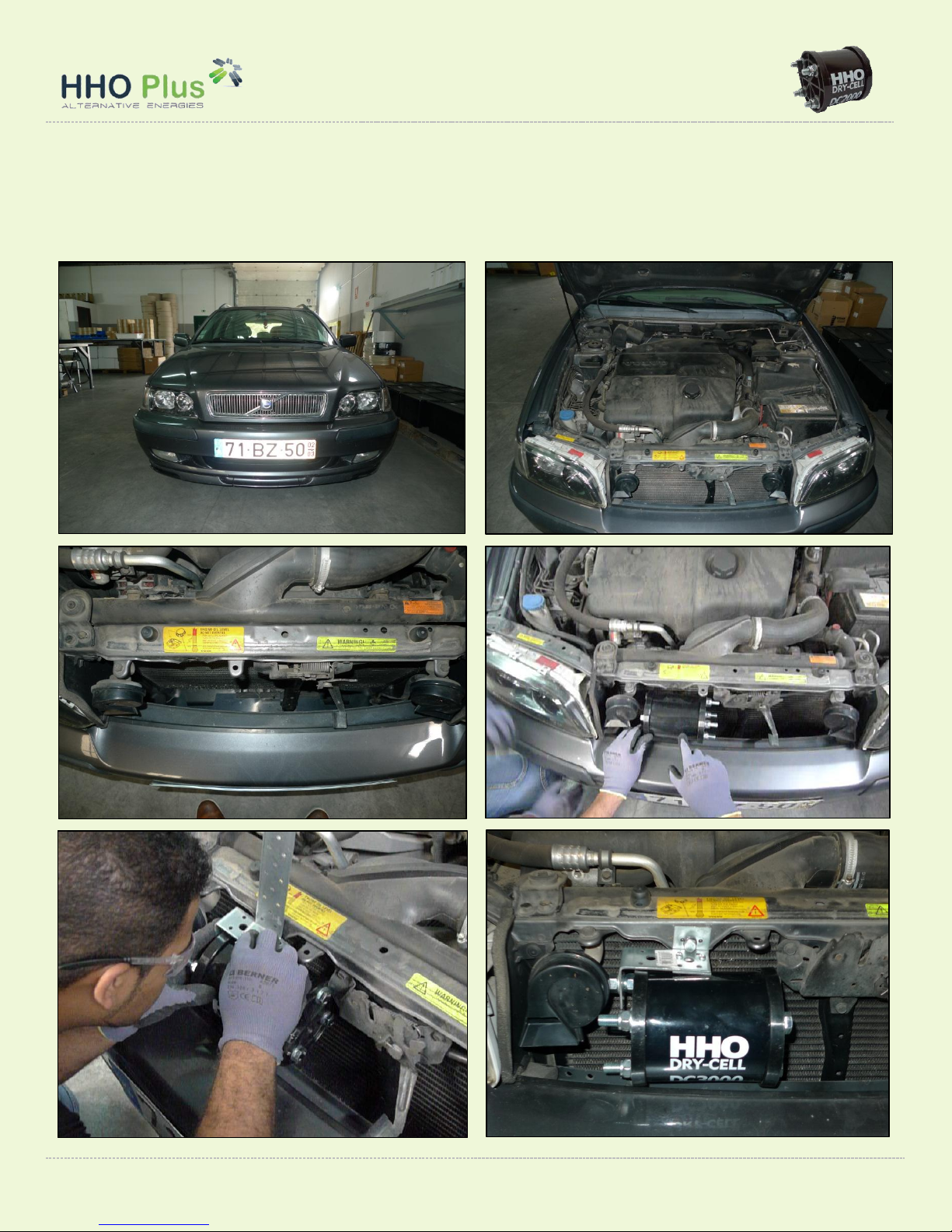
Install your new HHO Dry-Cell as far away from the heat of your engine as possible. Normally the best place
to install the dry-cell is in the space between the front grill and the radiator as it is closest to the air entering
the engine compartment and often the largest space available.
DC2000 –Installation Manual 7
HHO Plus, Alternative Energies, Lta –Travessa das Serras 33, Vieira de Leiria, Portugal –Tel. 00351244697116 –Email: [email protected]
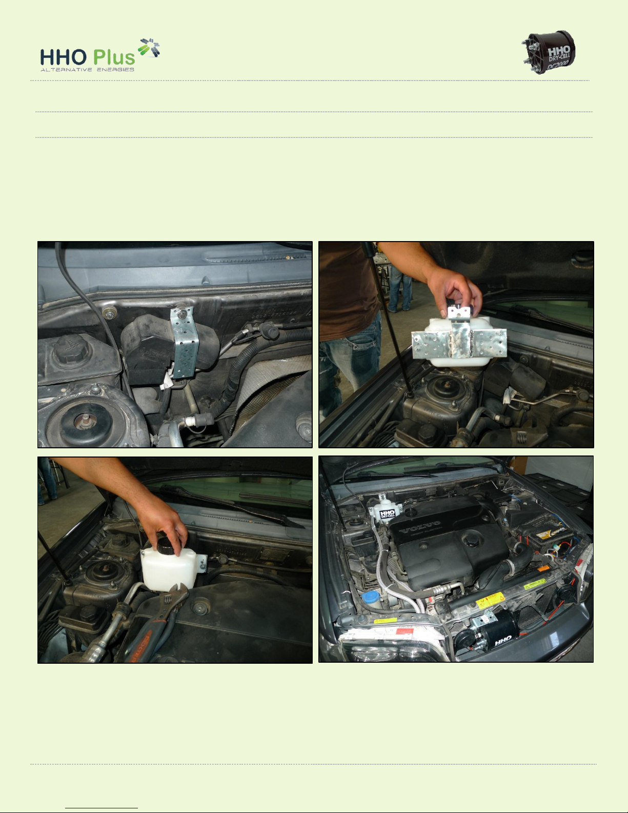
Make sure to install the Dry-Cell in a place that can easily be accessed
and cleaned or inspected from time to time. It should be mounted and
secured in such a manner as to ensure it does not move or bounce
around while the vehicle is in motion, even over rough terrain.
Securing it with a permanent metal bracket (see photos above –metal
bracket not included in the kit) should be sufficient to secure it to the
engine chassis and to operate perfectly.
The dry-cell can be mounted in horizontal
or vertical position.
The vertical position does not require any special remarks. The water
intake is connected in the bottom and HHO output will be in the top
of the cell. You just need to make sure that the HHO output hose is always above the top of the cell. If not the
HHO gas will have difficulties moving outside the cell and the production will be reduced.
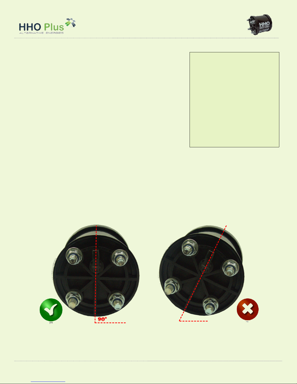
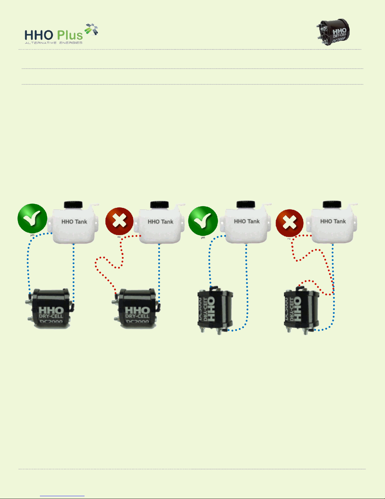
The horizontal position requires more care in the installation. The cell has to be positioned upright and
leveled to the ground with the tube fittings facing directly to the sky. If you look carefully the cell has 2
openings, one higher than the other. The lower opening is for the water intake and the upper opening for
HHO gas output. We must make sure that the cell is not placed with an angle/rotation that reduces the
distance between the two openings. Please take a look at the pictures below.
If the Dry-Cell is placed as shown in the image on the right you will not use 100% capacity of the generator to
produce HHO gas. Also the HHO gas will have problems getting out of the cell being released gulps. You can
verify this problem if fluctuation of the amperage is very high.
Important Information:
When making the installation
never make any type of
changes in the dry-cell.
Never open it, loosen/tighten
the nuts or cut the screws.
You will damage the dry-
cell and it will not work
properly after. Changes
made in the cell are not
covered by the warranty.
DC2000 –Installation Manual 8
HHO Plus, Alternative Energies, Lta –Travessa das Serras 33, Vieira de Leiria, Portugal –Tel. 00351244697116 –Email: [email protected]
Positioning the Water Tank
Make sure that water tank is installed with the same care as described before for the generator. The water
tank needs preferably to be placed 20 cm above the HHO dry-cell to accomplish the gravity head needed for
the water/hydrogen to flow into the generator. But in some cases with not too much space available to make
the installation we just need to make sure that the bottom of the water tank is a little bit higher than the top
of the dry-cell. Please take a look at the pictures below:
DC2000 –Installation Manual 9
HHO Plus, Alternative Energies, Lta –Travessa das Serras 33, Vieira de Leiria, Portugal –Tel. 00351244697116 –Email: [email protected]
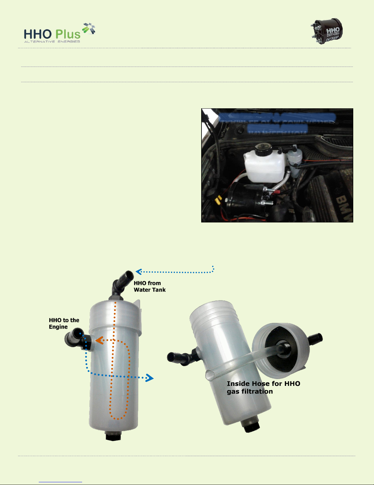
Positioning the Bubbler
The bubbler will serve two purposes: cleaning the HHO gas and act as a safety barrier. When HHO gas is
produced from the dry cell, some small water vapor is produced as well because the water will get a little bit
hot with the passage of current. This water vapor can
carry tiny particles of electrolyte which can cause
damaging corrosion. As the HHO bubbles rise up the
column of water inside the bubbler they are "scrubbed"
of any electrolyte particles that were attached to the
water vapor. The result is much cleaner HHO gas.
In the event of a flashback, the bubbler also acts as a
safety barrier. If a flame reaches the bubbler and ignites
the HHO that has accumulated at the top, the water
column will prevent the HHO from going on to the dry
cell because the flame cannot skip from bubble to
bubble.
Make sure that bubbler is installed above the water tank to accomplish the gravity head needed for a correct
“filtering” of the HHO gas. Please take a look at the pictures below:
EXAMPLE OF A COMPRESSED
INSTALLATION
DC2000 –Installation Manual 10
HHO Plus, Alternative Energies, Lta –Travessa das Serras 33, Vieira de Leiria, Portugal –Tel. 00351244697116 –Email: [email protected]
Positioning the water and HHO hoses
The hose connections on vertical position of the dry-cell do not require any special remarks. The water
intake is connected in the bottom and HHO output will be in the top of the cell. You just need to make sure
that the HHO output hose is always above the top of the cell. If not the HHO gas will have difficulties moving
outside the cell and the production will be reduced.
The hose connections on horizontal position of the dry-cell require only that the positioning of the HHO
output hose be made also always on an uprising position without ups and downs. If this happens, the HHO
gas will have problems moving into the water tank and will also be released gulps reducing the efficiency of
the system. You may verify this problem if fluctuation of the amperage on your system is very high. Please
refer to the illustration below for typical installation of the hoses coming and going from the water tank:

DC2000 –Installation Manual 11
HHO Plus, Alternative Energies, Lta –Travessa das Serras 33, Vieira de Leiria, Portugal –Tel. 00351244697116 –Email: [email protected]
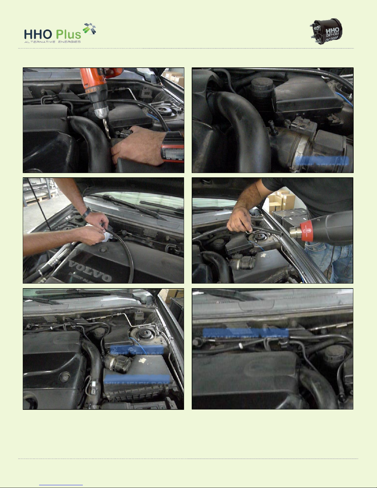
HHO injection point
The system is operated by vacuum suction from your car's air intake which takes the HHO directly to the
combustion chamber mixing it with the air/fuel. The injection point must be done right after the air filter box
and, in modern cars, after the MAF/MAP sensor (air flow sensor) and before the Turbo. Never make the
injection point after the Turbo or Intercooler because the pressure will not allow the best results with the
HHO system.
You will need to remove the air duct, to ensure that you do not leave any residue from the drilling you are
about to do. Drill an 8 mm hole close to the intake manifold. Clean out any drill shavings, insert the high
pressure fitting using goop glue or teflon tape and tighten. Connect the high pressure hose.
DC2000 –Installation Manual 12
HHO Plus, Alternative Energies, Lta –Travessa das Serras 33, Vieira de Leiria, Portugal –Tel. 00351244697116 –Email: [email protected]
MAF SENSOR
MAF SENSOR
AIR FILTER BOX
NON RETURN VALVE
DC2000 –Installation Manual 13
HHO Plus, Alternative Energies, Lta –Travessa das Serras 33, Vieira de Leiria, Portugal –Tel. 00351244697116 –Email: [email protected]
Installation of the electrical components
General configuration
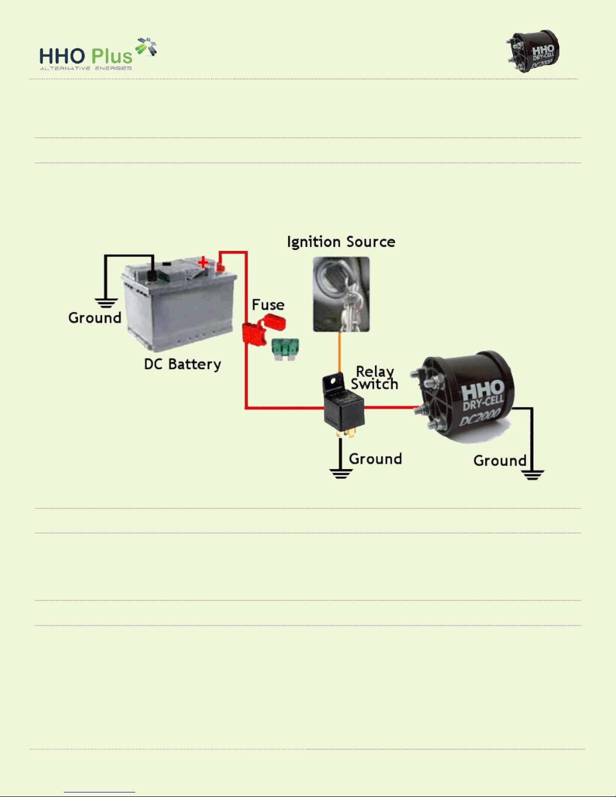
Please refer to the illustration below for typical wiring configuration for powering the system: In the end
pages of this manual you will be able to check each one of the individual connections to be made regarding
the installation of the electrical circuits. We will now only focus on the main aspects of the installation now.
Battery
The system is powered by the 12V battery and controlled by the relay switch. The system will only work if
there is a signal from the ignition source. The positive circuit (red wire) should be connected to the Relay
Switch position 30.
Identifying the ignition source
This is an important connection to be made in order to have the generator working only when the engine is
also working. Identify a point in your vehicle's electrical system which has 12 Volts (positive) present only
when the engine is running. The most secure connection is to excitement signal of the alternator. If you do
not know how to do this connection please ask you mechanic to do it for you. Connect this electric source to
the Relay Switch position 85. This circuit will control the HHO production.

DC2000 –Installation Manual 14
HHO Plus, Alternative Energies, Lta –Travessa das Serras 33, Vieira de Leiria, Portugal –Tel. 00351244697116 –Email: [email protected]
This electric connection can also be made to a circuit controlled by the ignition key (position 2), but there is a
risk of hydrogen being produced when the engine is not running if you leave the key permanently in that
position. Try never to make this kind of connection because it increases the risk of some explosion to happen.
Dry-Cell electric connections
Inside each one of the Dry Cells we have 19 plates, 4 of those with a configuration that allows the insertion of
yellow female spade connectors. Not all of the plates are connected because electrolysis would, in this
case, be very intense and damage the surface of the plates. We have to leave between the positive (+) and
the negative (-) some plates without connections –Neutral plates - in order to break the voltage and increase
the electrolysis efficiency with less heat production. Please refer to the picture below for typical wiring
connection of the dry-cells using 12v:
The positive circuit (red wire) should be connected to the Relay Switch position 87. Some relays present the
position 87a. Leave this connection with no connections. Connect the negative circuit (black wire) of the
Generator to a good ground source.
In the next page you can check some photos showing the right way to make the electric connections in the
dry-cell:

DC2000 –Installation Manual 15
HHO Plus, Alternative Energies, Lta –Travessa das Serras 33, Vieira de Leiria, Portugal –Tel. 00351244697116 –Email: [email protected]

DC2000 –Installation Manual 16
HHO Plus, Alternative Energies, Lta –Travessa das Serras 33, Vieira de Leiria, Portugal –Tel. 00351244697116 –Email: [email protected]
Water and electrolyte setup
Principles of the water electrolysis
Electrolysis of water is the decomposition of water molecule (H2O) into oxygen (O2) and hydrogen (H2) gases
due to an electric current passing in the water.
An electrical power source is connected to two electrodes, or two plates (typically made from some inert
metal such as stainless steel) which are placed in the water. In a properly designed cell, hydrogen will appear
at the cathode (the negatively charged electrode, where electrons enter the water), and oxygen will appear at
the anode (the positively charged electrode). The amount of hydrogen generated is twice the number of
moles of oxygen, and both are proportional to the total electrical charge.
Electrolysis of pure water requires excess energy in the form of potential to overcome various activation
barriers. Without the excess energy the electrolysis of pure water occurs very slowly or not at all. This is in
part due to the limited self- ionization of water. The efficacy of electrolysis is increased through the addition
of an electrolyte (such as a salt, an acid or a base).
Electrolyte concentration
The electrolyte should be added to the water the first time that
you use the system, and also when refilling, but in lower
quantities. Amperage should be measured to ensure the right
operative conditions according to the table below.
The electrolyte concentration to use in the HHO system depends
on the type of electrolyte and the purity of the product. The best
electrolytes are KOH (Potassium hydroxide) and NaOH (caustic
soda).
The more electrolyte you add to the water, the more amperage you will have in the system and also more
HHO gas will be produced. But, It is false to assume that a higher HHO gas production will mean a higher
fuel savings. There is an optimum point for all internal combustions engines. In diesel cars the system should
provide around 0,25 liter/min of HHO gas per each 1000 cm3of engine displacement. You will be meeting this
standard running your generator with:
Water is getting a brown color
after only a few hours
working?
You have too much electrolyte
in the system that is "eating"
the generator plates too fast.
Remove the water immediately
and start all over again.

DC2000 –Installation Manual 17
HHO Plus, Alternative Energies, Lta –Travessa das Serras 33, Vieira de Leiria, Portugal –Tel. 00351244697116 –Email: [email protected]
Engine Size
HHO (liter/min)
Start Amperage (A)
Final Amperage (A)
1 600 cc
0,40
5,5
6,5
1 800 cc
0,45
6,5
7,5
2 000 cc
0,50
7,0
8,0
2 200 cc
0,55
7,5
9,0
2 400 cc
0,60
8,0
10,0
* The values presented in the table may have a variation of ±15% according to the different driving and
mechanical conditions of each car.
For example, using KOH as electrolyte, with 90% purity, we should start using a concentration of 2% in the
water solution (20 g/liter). You should right after measure the current intensity going into the generator and
increase slowly the concentration until you reach the first standard operation amperage:
(example for a 2 liter engine –see table above)7,0 A 12V
The HHO generator will start producing HHO gas and temperature will increase with time making higher the
electric conductivity of the solution and amperage until we reach the final standard operation:
(example for a 2 liter engine –see table above)8,0 A 12V
Warning: Do not fall in the temptation of not measuring the current or increase the electrolyte concentration
more than is advised in this manual, because in long term, the generator will not work properly and you may
also not save any fuel.
Another thing that should consider is steam. Some of the early cell developers run their units with so much
amperage that the unit was producing more steam than HHO. If your unit runs hot to the touch, you must
suspect that at least part of your output is steam. One way to test for steam is to run your gas outlet over
some ice. If you get significant amounts of fog forming (water droplets), you know that at least part of your
output is steam.
Important
Remember that we are not changing diesel fuel for another type of fuel. We just want to put
enough HHO gas inside the engine to allow the normal diesel fuel to burn better thus
increasing fuel economy. If we put too much hydrogen we may not have any positive results
because we will be forcing the alternator and engine without increase in fuel efficiency.
DC2000 –Installation Manual 18
HHO Plus, Alternative Energies, Lta –Travessa das Serras 33, Vieira de Leiria, Portugal –Tel. 00351244697116 –Email: [email protected]
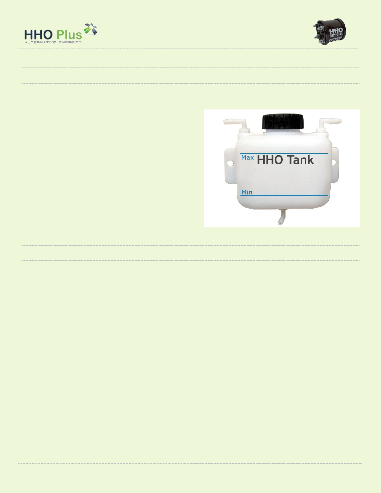
Water levels in the tank
Once you have your mixture ready, pour it into the top of the water tank, up to the water level line shown in
the picture bellow. Try to only fill your unit about 70% full. This is imperative to allow the HHO produced to
enter the gap left in the Tank and avoid any risks of some
water getting into the engine.
The standard water tank is a 1,2 liters unit which will
provide you with approximately 800 kilometers of
driving. Be sure to make your maintenance plan with that
in mind and refill the tank when it is required. Try to refill
as often as it is possible for you in order to keep the
generator running cool.
In our store we have a product that can help you to
control better the water levels in the water tank and
reduce the problems with the management of the
system. It is called the water level control switch.
Amperage variation in the system
When operating the system the water molecule will be "brocken" into HHO gas to be used by the engine. The
water level in the tank will slowly go down but the electrolyte will continue in the system with an increase of
the concentration and, therefore, amperage being drawn into the generator. This means that when you start
using the system, with the tank full (Max level), you have 8,0A and after some time when the tank is at the
lower point (Min level) you will have 10,0A
If you put too much electrolyte, there are a combination of heating factors at work and can cause a situation
called Thermal Runaway, where an increase in ambient temperature combined with excess electrolyte mix
leads to overheating in the generator shortening the “life” of system.
When applying a direct current to the HHO generator, a high resistance will be present in the water
(electrolyte mixture). High resistance generates heat causing the water to heat up. As the temperature rises,
the resistance in the water goes down, allowing more current to pass through the fuel cell. By the end of the
day, the current will be higher than the value you started with at the beginning of the day. One way to control
this is using a PWM –Pulse Width Modulator
DC2000 –Installation Manual 19
HHO Plus, Alternative Energies, Lta –Travessa das Serras 33, Vieira de Leiria, Portugal –Tel. 00351244697116 –Email: [email protected]
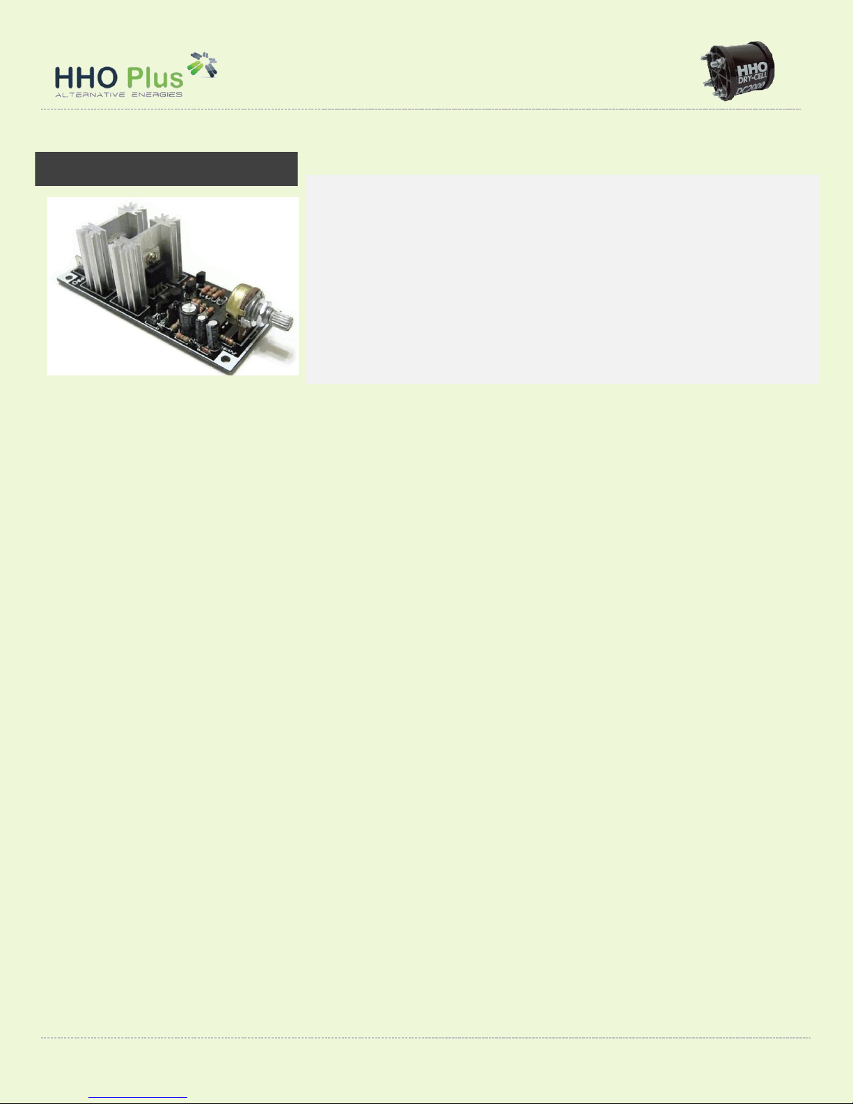
PWM PULSE WIDTH MODULATOR
Pulse Width Modulation, is a method of transmitting information on a series of
pulses, changing the frequency, rather than a continuously varying analog signal. It
will allow you to control the amperage going into the generator in a very easy way.
This ability keeps the cell running at cool operating temperatures and prolongs the
life of the cell while increasing the HHO output
Efficiency: HHO generators will run cooler than standard linear power amps,
requiring substantially less heat sink mass;
Amperage control: the control of the amperage going into the generator will be very
easy to control. The ability to control the amperage keeps the cell running at cool
operating temperatures and prolongs the life of the cell while increasing the HHO
output.

DC2000 –Installation Manual 20
HHO Plus, Alternative Energies, Lta –Travessa das Serras 33, Vieira de Leiria, Portugal –Tel. 00351244697116 –Email: [email protected]
Electronic fuel injection
Basic Information
When adding a HHO gas to the engine of an old car, we will see immediate economies in fuel consumption.
However, this is not the case for some modern electronic fuel injected vehicles equipped with an engine
control unit (ECU), because the fuel burned inside the cylinders has significantly improved, but the sensors
continue expecting the same amount of unburned oxygen to come out of the exhaust of the engine.
This causes a signal to be fed back to the ECU, that after will give orders to inject more fuel increasing the
air/fuel mixture (Richer), which will counter act the fuel gains you may be expecting.
So we need to make some changes according to the cars*
1
. The different possibilities are:
1.1 Petrol Engines –Carburetor (before 1992)
Fuel savings: 30 –45%
Requirements: Right amount of HHO inside the engine. Tune the carburetor.
1.2 Petrol Engines –Electronic Injection (1992-2001)
Fuel savings: 20 –30%
Requirements: Right amount of HHO inside the engine. Reset the ECU. Install the lambda sensor extender.
Isolate the body of the lambda sensors;
Optional: MAF/MAP Sensor Enhancer to increase fuel savings
1.3. Petrol Engines –Electronic Injection (2001-2012)
Option 1
Fuel savings: 20 –30%
Requirements: Right amount of HHO inside the engine. Reset the ECU. Install the lambda sensor extender.
Isolate the body of the lambda sensors;
Optional: MAF/MAP Sensor Enhancer to increase fuel savings
Option 2
Fuel savings: 25 –35%
Requirements: Right amount of HHO inside the engine. Reset the ECU. Install the HEC Chip
2.1. Diesel Engines –Mechanic Pump (before 1998)
Fuel savings: 20 –35%
Requirements: Right amount of HHO inside the engine. Tune the injection rate of the fuel pump.
1
The dates can change according to each country and manufacturers.
Table of contents
Other HHO Plus Automobile Accessories manuals


Popular Automobile Accessories manuals by other brands

WeatherTech
WeatherTech No-Drill MudFlap installation instructions

Goobay
Goobay 11425 user manual

Classic Accessories
Classic Accessories QuadGear Extreme ATV EVOLUTION FRONT RACK... quick start guide

Audiovox
Audiovox 50-0312x SERIES installation instructions

Thule
Thule 1101 instructions

Prorack
Prorack K1215 instructions

Circutor
Circutor Raption 150C Series instruction manual

Conrad
Conrad TK-3008-4 operating instructions

Metra Electronics
Metra Electronics 99-5500 installation instructions

ECS Electronics
ECS Electronics HY-046-DG Fitting instructions electric wiring

Bully Dog
Bully Dog GTX user manual

Opel
Opel OPEL INSIGNIA Infotainment manual


