HHP Scanteam 4800 User manual

™
IMAGETEAM™ 4600/4800
Retail /Commercial Area Imager
User’s Guide


Statement of Agency Compliance
This device complies with part 15 of the FCC Rules. Operation is subject to the
following two conditions: (1) this device may not cause harmful interference, and
(2) this device must accept any interference received, including interference that
may cause undesired operation.
FCC Class B Compliance Statement
This equipment has been tested and found to comply with the limits for a Class
B digital device pursuant to part 15 of the FCC Rules. These limits are designed
to provide reasonable protection against harmful interference in a residential
installation. This equipment generates, uses, and can radiate radio frequency
energy and, if not installed and used in accordance with the instructions, may
cause harmful interference to radio communications. However, there is no
guarantee that interference will not occur in a particular installation. If this
equipment does cause harmful interference to radio or television reception,
which can be determined by turning the equipment off and on, the user is
encouraged to try to correct the interference by one or more of the following
measures:
•Reorient or relocate the receiving antenna.
•Increase the separation between the equipment and receiver.
•Connect the equipment into an outlet on a circuit different from that to
which the receiver is connected.
•Consult the dealer or an experienced radio or television technician for
help.
Caution: Any changes or modifications made to this device that are not
expressly approved by Hand Held Products, Inc. may void the user’s authority to
operate the equipment.
Note: To maintain compliance with FCC Rules and Regulations, cables
connected to this device must be shielded cables, in which the cable shield
wire(s) have been grounded (tied) to the connector shell.
Canadian Notice
This equipment does not exceed the Class B limits for radio noise emissions as
described in the Radio Interference Regulations of the Canadian Department of
Communications.
Le present appareil numerique n’emet pas de bruits radioelectriques depassant
les limites applicables aux appareils numeriques de la classe B prescrites dans
le Reglement sur le brouillage radioelectrique edicte par le ministere des
Communications du Canada.

The CE mark on the product indicates that the system has been
tested to and conforms with the provisions noted within the 89/336/
EEC Electromagnetic Compatibility Directive and the 73/23/EEC
Low Voltage Directive.
Complies with:
EN55022:1998 (for ITE emissions)
EN55024:1998 (for ITE immunity), including CISPR 22B:1997
EN61000-4-2:1995
EN61000-4-3:1995
For further information please contact:
Hand Held Products, Inc.
Nijverheidsweg 9
5627 BT Eindhoven
The Netherlands
HHP shall not be liable for use of our product with equipment (i.e., power
supplies, personal computers, etc.) that is not CE marked and does not comply
with the Low Voltage Directive.
UL and cUL Statement
UL listed UL1950 and CSA 22.2 No.950. cUL listed UL1950 and CSA 22.2 No
950.
LED Safety Statement
This device has been tested in accordance with EN60825-1 LED safety, and has
been certified to be under the limits of a Class 1 LED device.
TÜV Statement
TÜV or GS marked to EN60950 and EN60825-1.
C-Tick Statement
Conforms to AS/NZS 3548. C-Tick number: N10410.
Mexico
Certified
Patents
Please refer to the IT4600/4800 packaging for a list of patents.

Solids and Water Protection
The IT4600 has a rating of IP41, immunity of foreign particles and dripping water.
The IT4800 has a rating of IP54, immunity of windblown dust penetration and
splashing water.

Disclaimer
HandHeldProducts,Inc.,d/b/aHHP(“HHP”)reservestherighttomakechanges
in specifications and other information contained in this document without prior
notice, and the reader should in all cases consult HHP to determine whether any
such changes have been made. The information in this publication does not
represent a commitment on the part of HHP.
HHP shall not be liable for technical or editorial errors or omissions contained
herein;nor forincidental orconsequential damages resulting from the furnishing,
performance, or use of this material.
This document contains proprietary information which is protected by copyright.
All rights are reserved. No part of this document may be photocopied,
reproduced, or translated into another language without the prior written consent
of HHP.
©2002-2003 Hand Held Products, Inc., All rights reserved.
Web Address: www.hhp.com
Microsoft®Windows®iseitheraregisteredtrademarkortrademarksofMicrosoft
Corporation in the United States and/or other countries.
Macintosh®is a trademark of Apple Computer, Inc., registered in the U.S. and
other countries.
Other product names mentioned in this document may be trademarks or
registered trademarks of other companies and are the property of their
respective owners.

i
Chapter 1 - Getting Started
About This Manual............................................................... 1-1
Unpacking the Imager........................................................... 1-1
IT4600/4800 Models ............................................................ 1-2
IT4600/4800 Imager Identification....................................... 1-3
Connecting the Imager When Powered by Host
(Keyboard Wedge)............................................................. 1-4
Reading Techniques.............................................................. 1-5
Plug and Play........................................................................ 1-6
Keyboard Wedge............................................................ 1-6
Laptop Direct Connect................................................... 1-6
RS-232............................................................................ 1-7
Wand Emulation Plug & Play............................................... 1-7
IBM 4683 Ports 5B, 9B, and 17 Interface...................... 1-8
Connecting the Imager with USB......................................... 1-9
IBM SurePos................................................................ 1-10
USB PC or Macintosh®Keyboard............................... 1-10
USB HID...................................................................... 1-11
USB COM Port Emulation........................................... 1-11
Connecting the Imager with Serial Wedge......................... 1-12
Chapter 2 - Terminal Interfaces
Terminal ID .......................................................................... 2-1
Supported Terminals............................................................. 2-2
Keyboard Country ................................................................ 2-4
Keyboard Style ..................................................................... 2-6
Keyboard Modifiers.............................................................. 2-7
Connecting the Imager with RS-232 Serial Port .................. 2-9
RS-232 Baud Rate........................................................ 2-10
RS-232 Word Length: Data Bits, Stop Bits, and Parity2-11
RS-232 Receiver Time-Out.......................................... 2-12
RS-232 Handshaking ................................................... 2-12
Wand Emulation Connection....................................... 2-13
Table of Contents

ii
Wand Emulation..................................................................2-14
Data Block Size............................................................2-14
Delay Between Blocks..................................................2-14
Overall Checksum ........................................................2-15
Wand Emulation Transmission Rate............................2-15
Wand Emulation Polarity .............................................2-16
Wand Emulation Idle....................................................2-16
Chapter 3 - Output
Good Read Indicators............................................................3-1
Beeper – Good Read.......................................................3-1
Beeper Volume – Good Read.........................................3-1
Beeper Pitch – Good Read..............................................3-2
Beeper Duration – Good Read........................................3-2
LED – Good Read ..........................................................3-2
Number of Beeps – Good Read......................................3-3
Good Read Delay..................................................................3-3
User-Specified Good Read Delay.........................................3-3
Trigger Modes.......................................................................3-4
Manual/Serial Trigger.....................................................3-4
Scan Stand Mode...................................................................3-5
Scan Stand Symbol.........................................................3-5
Presentation Mode.................................................................3-6
Presentation LED Timer.................................................3-6
Presentation Sensitivity ..................................................3-7
Hands Free Time-Out............................................................3-7
Reread Delay.........................................................................3-7
User-Specified Reread Delay................................................3-8
LED Power Level..................................................................3-9
Illumination Lights................................................................3-9
Imager Time-Out.................................................................3-10
Aimer Delay........................................................................3-10
User-Specified Aimer Delay ........................................3-10
Aimer Mode........................................................................3-11
Centering.............................................................................3-11
Decode Search Mode ..........................................................3-13

iii
Output Sequence Overview.................................................3-14
Output Sequence Editor................................................3-16
Require Output Sequence .............................................3-16
Multiple Symbols................................................................3-17
No Read...............................................................................3-17
Print Weight ........................................................................3-18
Video Reverse .....................................................................3-18
Working Orientation............................................................3-19
Chapter 4 - Data Editing
Prefix/Suffix Overview .........................................................4-1
To Add a Prefix or Suffix:..............................................4-2
To Clear One or All Prefixes or Suffixes: ......................4-3
To Add a Carriage Return Suffix to all Symbologies.....4-3
Prefix Selections .............................................................4-4
Suffix Selections.............................................................4-4
Function Code Transmit .................................................4-4
Intercharacter, Interfunction, and Intermessage Delays........4-5
Intercharacter Delay........................................................4-5
User Specified Intercharacter Delay...............................4-6
Interfunction Delay.........................................................4-6
Intermessage Delay.........................................................4-7
Chapter 5 - Data Formatting
Data Format Editor Introduction...........................................5-1
To Add a Data Format ....................................................5-1
Other Programming Selections.......................................5-2
Data Format Editor Commands......................................5-2
Data Format Editor .........................................................5-5
Data Formatter................................................................5-5
Alternate Data Formats...................................................5-6
Chapter 6 - Secondary Interface
Secondary RS-232 Connection .............................................6-2
Secondary Code 39 Wand Emulation ...................................6-2

iv
Wand/Laser Emulation Multi Block.....................................6-3
Delay Between Blocks....................................................6-3
Overall Checksum ..........................................................6-3
Wand Emulation Transmission Rate..............................6-4
Wand Emulation Polarity ...............................................6-4
Wand Emulation Idle......................................................6-5
Data Block Size..............................................................6-5
Secondary Laser Emulation ..................................................6-5
Laser Emulation Transmission Rate .....................................6-6
Laser Emulation Polarity.......................................................6-6
Laser Emulation Idle.............................................................6-7
Secondary Trigger Mode.......................................................6-7
Manual/Serial Trigger.....................................................6-7
Hands Free Time-Out............................................................6-8
Scan Stand Mode...................................................................6-9
Scan Stand Symbol.........................................................6-9
Presentation Mode...............................................................6-10
Chapter 7 - Symbologies
All Symbologies ...................................................................7-2
Message Length Description.................................................7-2
Codabar ................................................................................7-3
Codabar Start/Stop Characters.......................................7-3
Codabar Check Character...............................................7-4
Codabar Concatenation...................................................7-5
Codabar Message Length ...............................................7-5
Code 39 ................................................................................7-6
Code 39 Start/Stop Characters.......................................7-6
Code 39 Check Character...............................................7-7
Code 39 Message Length ...............................................7-7
Code 39 Append.............................................................7-8
Code 32 Pharmaceutical (PARAF).................................7-8
Full ASCII ......................................................................7-9
Code 39 Code Page.......................................................7-10

v
Interleaved 2 of 5 ................................................................7-10
Check Digit...................................................................7-11
Interleaved 2 of 5 Message Length...............................7-11
Code 93 ...............................................................................7-12
Code 93 Message Length..............................................7-12
Code 93 Code Page.......................................................7-13
Code 2 of 5 .........................................................................7-13
Code 2 of 5 Message Length ........................................7-13
IATA Code 2 of 5 ...............................................................7-14
IATA Code 2 of 5 Message Length..............................7-14
Matrix 2 of 5 .......................................................................7-15
Matrix 2 of 5 Message Length......................................7-15
Code 11 ...............................................................................7-16
Check Digits Required..................................................7-16
Code 11 Message Length..............................................7-16
Code 128 .............................................................................7-17
ISBT 128 Concatenation...............................................7-17
Code 128 Message Length............................................7-18
Code 128 Code Page.....................................................7-18
Telepen ...............................................................................7-18
Telepen Output .............................................................7-19
Telepen Message Length ..............................................7-19
UPC-A ................................................................................7-19
UPC-A Check Digit......................................................7-20
UPC-A Number System................................................7-20
UPC-A Addenda...........................................................7-20
UPC-A Addenda Required ...........................................7-21
UPC-A Addenda Separator...........................................7-21

vi
UPC-A/EAN-13
with Extended Coupon Code ...........................................7-21
UPC-E0 ..............................................................................7-22
UPC-E0.........................................................................7-22
UPC-E0 Expand ...........................................................7-22
UPC-E0 Addenda Required..........................................7-23
UPC-E0 Addenda Separator.........................................7-23
UPC-E0 Check Digit....................................................7-23
UPC-E0 Number System..............................................7-24
UPC-E0 Addenda.........................................................7-24
UPC-E1 ..............................................................................7-24
EAN/JAN-13 ......................................................................7-25
EAN/JAN-13 Check Digit............................................7-25
EAN/JAN-13 Addenda.................................................7-26
EAN/JAN-13 Addenda Required.................................7-26
EAN/JAN-13 Addenda Separator ................................7-26
ISBN Translate.............................................................7-27
EAN/JAN-8 ........................................................................7-27
EAN/JAN-8 Check Digit..............................................7-27
EAN/JAN-8 Addenda...................................................7-28
EAN/JAN-8 Addenda Required...................................7-28
EAN/JAN-8 Addenda Separator ..................................7-28
MSI .....................................................................................7-29
MSI Check Character ...................................................7-29
MSI Message Length....................................................7-30
Plessey Code ......................................................................7-30
Plessey Message Length...............................................7-30
RSS-14 ...............................................................................7-31
RSS Limited .......................................................................7-31
RSS Expanded ....................................................................7-32
RSS Expanded Message Length...................................7-32
PosiCode ............................................................................7-33
PosiCode Message Length............................................7-33
Trioptic Code .....................................................................7-34
Codablock F .......................................................................7-34
Codablock F Message Length ......................................7-35

vii
Code 16K ............................................................................7-35
Code 16K Message Length...........................................7-35
Code 49 ...............................................................................7-36
Code 49 Message Length..............................................7-36
PDF417 ...............................................................................7-37
PDF417 Message Length..............................................7-37
MicroPDF417 .....................................................................7-37
MicroPDF417 Message Length....................................7-38
EAN•UCC Composite Codes .............................................7-38
UPC/EAN Version........................................................7-39
EAN•UCC Composite Code Message Length..............7-39
EAN•UCC Emulation .........................................................7-40
TCIF Linked Code 39 (TLC39) .........................................7-40
Postal Codes .......................................................................7-41
Postnet...........................................................................7-41
Planet Code...................................................................7-42
British Post....................................................................7-42
Canadian Post ...............................................................7-42
Kix (Netherlands) Post..................................................7-43
Australian Post..............................................................7-43
Japanese Post ................................................................7-43
China Post ...........................................................................7-44
China Post Message Length..........................................7-44
Korea Post ..........................................................................7-45
Korea Post Message Length .........................................7-45
QR Code .............................................................................7-46
QR Code Message Length............................................7-46
Data Matrix .........................................................................7-47
Data Matrix Message Length........................................7-47
MaxiCode ...........................................................................7-48
MaxiCode Message Length ..........................................7-48
Aztec Code .........................................................................7-49
Aztec Code Message Length ........................................7-49
Aztec Runes..................................................................7-49

viii
Chapter 8 - Imaging Commands
Image Snap - IMGSNP .........................................................8-1
IMGSNP Modifiers ........................................................8-1
Image Ship - IMGSHP..........................................................8-2
IMGSHP Modifiers ........................................................8-3
Intelligent Signature Capture - IMGBOX.............................8-6
IMGBOX Modifiers.......................................................8-7
Chapter 9 - OCR Programming
OCR Fonts ............................................................................9-2
OCR.......................................................................................9-2
U.S. Currency Font ..............................................................9-3
MICR E13 B Font ................................................................9-3
SEMI Font ............................................................................9-4
OCR Templates.....................................................................9-4
Creating an OCR Template ............................................9-5
Stringing Together Multiple Formats
(Creating “Or” Statements) ............................................9-7
OCR User-Defined Variables ...............................................9-7
Reading Multi-Row OCR...............................................9-8
OCR Check Character...........................................................9-9
OCR Modulo 10 Check Character..................................9-9
OCR Modulo 36 Check Character................................9-10
OCR User-Defined Check Character..................................9-10
Weighting Options........................................................9-11
OCR ISBN Application Example .......................................9-13
OCR Template Codes .........................................................9-14
Chapter 10 - Interface Keys
Keyboard Function Relationships.......................................10-1
Supported Interface Keys....................................................10-3

ix
Chapter 11 - Utilities
To Add a Test Code I.D. Prefix to All Symbologies ..........11-1
Show Software Revision .....................................................11-1
Show Data Format...............................................................11-1
Resetting the Standard Product Defaults.............................11-1
Test Menu............................................................................11-2
2D PQA (Print Quality Assessment)...................................11-2
Visual Menu 2003...............................................................11-2
Installing Visual Menu 2003 from the Web .................11-3
Quick*View.........................................................................11-4
Installing Quick*View from the Web...........................11-4
Chapter 12 - Serial Programming Commands
Conventions.........................................................................12-1
Menu Command Syntax......................................................12-1
Query Commands .........................................................12-2
Concatenation of Multiple Commands.........................12-2
Responses......................................................................12-2
Examples of Query Commands....................................12-3
Trigger Commands..............................................................12-4
Resetting the Standard Product Defaults.............................12-4
Menu Commands ................................................................12-5
Terminal Interfaces ...............................................12-5
Output Selections ..................................................12-8
Prefix/Suffix Selections .......................................12-11
Data Formatter Selections ...................................12-12
Secondary Interface Selections ...........................12-12
Symbologies ........................................................12-13
Imaging Default Commands ...............................12-22
Image Snap ..........................................................12-22
Image Snap (continued) ......................................12-23
OCR Selections ...................................................12-25

x
Chapter 13 - Product Specifications
IT4600 Product Specifications............................................13-1
IT4800 Product Specifications............................................13-2
Standard Cable Pinouts.......................................................13-4
Chapter 14 - Maintenance
Repairs.................................................................................14-1
Maintenance........................................................................14-1
Cleaning the Imager’s Window....................................14-1
Inspecting Cords and Connectors.................................14-1
Replacing the Interface Cable.......................................14-2
Troubleshooting ..................................................................14-3
Chapter 15 - Customer Support
Obtaining Factory Service...................................................15-1
Technical Assistance...........................................................15-2
Limited Warranty .........................................................15-3
Appendix A
Symbology Chart .................................................................A-1
ASCII Conversion Chart (Code Page 1252)........................A-3
Code Page Mapping of Printed Bar Codes ..........................A-5

IMAGETEAM™ 4600/4800 User’s Guide 1 - 1
1
Getting Started
TheIMAGETEAM™ 4600 and 4800 marka newperformance levelfor handheld
area imagers. The IT4600/4800 hand held area imagers are powered by HHP’s
AdaptusTM technology. The performance of Adaptus technology delivers
aggressive read rates and depths of field on 1D, stacked linear, and matrix
codes. This aggressiveness applies even in challenging reading environments
where low lighting conditions and poor quality might make it difficult to read bar
codes. Adaptus technology ensures your investment will continue to supply
years of use by reading any bar codes you require, now or in the future.
Designed for today’s demanding retail and commercial environments, the
IT4600 offers superior image quality, speed, durability, and the ability to read
poor quality bar codes. The IT4600 is comfortable to hold, easy to use, rugged,
and excellent for retail applications, as well as for all general scanning and
imaging applications.
The IT4800 hand held industrial area imager is the first industrial class area
imager powered by Adaptus technology. The IT4800 has a similar ergonomic
design as the IT4600, but has a more rugged housing, and is built to withstand
your toughest industrial applications.
About This Manual
This User’s Guide provides installation and programming instructions for the
IMAGETEAM 4600/4800. Product specifications, dimensions, warranty, and
customer support information are also included.
HHP’s bar code imagers are factory programmed for the most common terminal
and communications settings. If you need to change these settings,
programming is accomplished by scanning the bar codes in this guide.
An asterisk (*) next to an option indicates the default setting.
Unpacking the Imager
After you open the shipping carton containing the IT4600/4800, take the
following steps:
• Check to make sure everything you ordered is present.
• Save the shipping container for later storage or shipping.
• Check for damage during shipment. Report damage immediately to the
carrier who delivered the carton.

1 - 2 IMAGETEAM™ 4600/4800 User’s Guide
IT4600/4800 Models
There are three models of the IT4600/4800 imager, which may be used with
many interfaces described in this manual. Refer to the chart below to determine
the models that can be used with your interface.
The following interfaces apply to all IT4600/4800 focal distances and decoding
options. Refer to Chapter 6 for programming information regarding secondary
interfaces.
Models Primary Secondary
4600XX00XX
4800XX00XX TTL Level 232, USB COM port
emulation Lower Power Laser
Emulation
4600XX03XX
4800XX03XX True RS-232, True RS-232
serial wedge True RS-232
4600XX05XX
4800XX05XX Keyboard wedge, TTL level
232, TTL level 232 serial
wedge, IBM 4683, wand emula-
tion, USB keyboard, USB HID,
USB retail (IBM SurePOS),
USB COM port emulation
Wand Emulation, TTL
level 232

IMAGETEAM™ 4600/4800 User’s Guide 1 - 3
IT4600/4800 Imager Identification
1 - 4 IMAGETEAM™ 4600/4800 User’s Guide
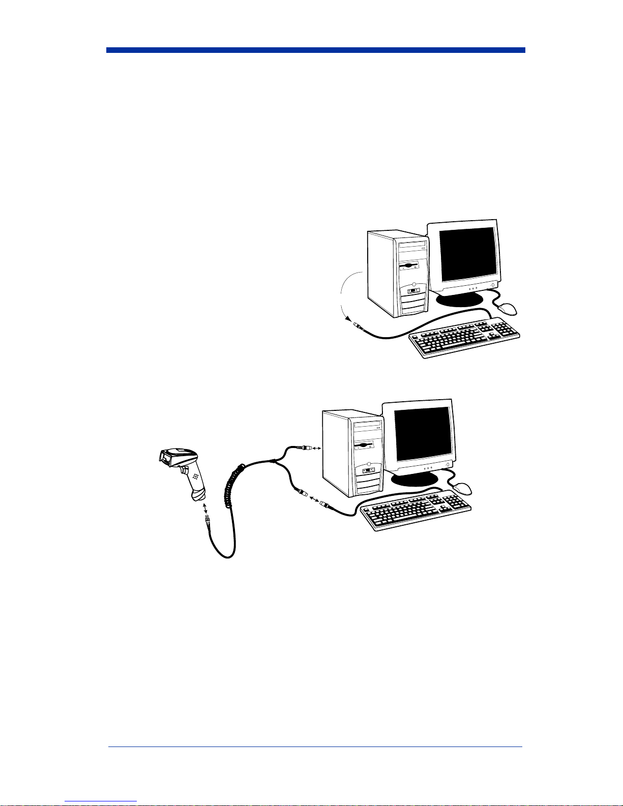
Connecting the Imager When Powered by Host
(Keyboard Wedge)
A imager can be connected between the keyboard and PC as a “keyboard
wedge,” plugged into the serial port, or connected to a portable data terminal in
wand emulation or non decoded output mode. The following is an example of a
keyboard wedge connection:
1. Turn off power to the terminal/computer.
2. Disconnect the keyboard cable
from the back of the terminal/
computer.
3. Connect the appropriate interface cable to the imager and to the terminal/
computer.
4. Turn the terminal/computer power back on. The imager beeps.
5. Verify the imager operation by scanning a bar code from the Sample
Symbols in the back of this manual. The imager beeps once.
Disconnect
12
3
This manual suits for next models
2
Table of contents
Other HHP Barcode Reader manuals

Popular Barcode Reader manuals by other brands


Motorola
Motorola Symbol DS6708 Product reference guide

Datalogic
Datalogic QuickScan QBT24 series Product reference guide

RIOTEC
RIOTEC LS6302A Programming Quick Guide

Custom Audio Electronics
Custom Audio Electronics mplus2 user manual

Datalogic
Datalogic DX8200A Reference manual

Symbol
Symbol DS3408-SF20005R Specifications


