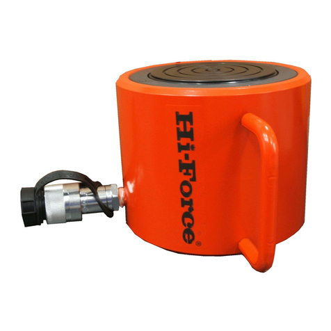
Hi-Force HVL Series User manual

INSTRUCTION MANUAL –HYDRAULIC CYLINDERS:
Model Series: HVL, HPS, HLS, HSS, HAS, HHA, HHS, HHR, HDA, HFL, HFG, HSG, HGG, HPC.
Hi-Force Limited –Prospect Way –Daventry –Northants NN11 8PL –United Kingdom
Tel: +44(0) 1327 301000: Fax: +44(0) 1327 706555: Website: www.hi-force.com
NOTE: Spare parts sheets for these products are
available from the Hi-Force website at:
www.hi-force.com
or from your local regional Hi-Force Sales office or
authorized local Hi-Force distributor.
1.0 Inspection of the product upon receipt:
On receipt of the product, visually inspect the item
for any evidence of shipping damage. Please note
shipping damage is not covered by warranty. If
shipping damage is found notify the carrier
immediately and refrain from putting the product
into service. The carrier is responsible for repair
and replacement costs resulting from damage in
transit shipment.
2.0 Safety Precautions:
Read and follow all the instructions and safety
warnings carefully prior to use of the equipment.
Failure to do so could result in equipment damage
or failure of the equipment or personal injury. Hi-
Force will not be held responsible for any damage
to the equipment or personal injury resulting from
unsafe use of the product, lack of maintenance or
incorrect operation. If in doubt on the correct usage
of any Hi-Force equipment, contact your nearest Hi-
Force office or distributor. If the operator has not
been trained on high pressure hydraulic equipment
and its safe use consult your local Hi-Force sales
office who can offer you training courses for
operators.
All operators should ensure that all necessary
personal protective equipment as specified by their
employer is worn when operating any hydraulic
equipment. Safety shoes, safety glasses/ visor and
protective gloves should be worn at all times. All
relevant risk assessments should be completed
prior to use of the equipment.
Warning: Do not work under a load supported
only by hydraulic means. A cylinder, when used as a
lifting device should not be used as a load holding
device. All loads once lifted, should be supported by
rigid mechanical means. If load holding is required
by the application where external mechanical
means cannot be used, HFG/HFL Failsafe cylinders
should be considered. To avoid personal injury keep
hands and feet clear of the cylinder and workpiece
during operation.
Do not exceed the rated capacity of the
hydraulic cylinder and never attempt to lift a load
greater than the stated capacity of the cylinder. Hi-
Force hydraulic cylinders are designed for a
maximum working pressure of 700 BAR (10,000
PSI). Do not connect a pump with a higher rated
pressure capacity to any Hi-Force cylinder of this
model series.
Keep hydraulic equipment away from flames
and direct heat.
Hydraulic equipment must only be serviced by a
qualified technician.
To protect your warranty, only use Hi-Force’s
hydraulic oil.
Immediately replace any worn or damaged parts
using genuine Hi-Force parts only.
Do not adjust the external pressure relief valve on
any Hi-Force cylinder.
The system operating pressure must not exceed the
pressure rating of the lowest component in the
system. Where possible, use a pressure gauge to
monitor the system.
Avoid damaging hydraulic hose. Always route hoses
to ensure that they are free from sharp bends and
kinks. Using a bent or kinked hose will cause severe
back-pressure and can also lead to the failure of the
hose.
Never lift or carry any hydraulic components
by the hose or hoses connected to them.
Do not handle a pressurized hydraulic hose.
Oil escaping under pressure from a ruptured
hose can penetrate the skin and lead to a serious
medical emergency and in certain cases death.
Should this incident happen medical attention must
be sought immediately.

INSTRUCTION MANUAL –HYDRAULIC CYLINDERS:
Model Series: HVL, HPS, HLS, HSS, HAS, HHA, HHS, HHR, HDA, HFL, HFG, HSG, HGG, HPC.
Hi-Force Limited –Prospect Way –Daventry –Northants NN11 8PL –United Kingdom
Tel: +44(0) 1327 301000: Fax: +44(0) 1327 706555: Website: www.hi-force.com
Always operate the system under no load condition
prior to the actual lift to ensure that no air is
trapped in the hydraulic circuit.
Do not drop or place heavy objects on a hydraulic
hose as this will cause internal damage to the hose
which could result in rupture when the hose is
pressurized and could result in serious damage to
components, and possible serious personal injury
to operating personnel.
Lifting cylinders should always be placed on a flat
even surface that can support the load to be
applied.
Avoid lifting loads that are not central to the lifting
piston. Avoid offset loading as this can damage the
cylinder bores and piston rods, and also lead to
unstable load lifting.
Where applicable, use an additional cylinder
support base to assist in supporting the load to be
lifted.
Do not weld items to the cylinder or modify the
cylinder in any way from its delivered condition.
This will invalidate your warranty, and could lead to
serious personal injury.
Only use hydraulic cylinders in a completed, tested
coupled system. Never attempt to use a cylinder
that is not correctly coupled to its operational
pump.
If hydraulic cylinders are overloaded to
extreme degrees, this could in extreme cases
to component failure and may lead to serious
personal injury.
3.0 Cylinder Type Components:
4.0 Installation –Connection and Bleeding:
Ensure that the hydraulic pump being used is
suitable for the cylinder/s it is to be connected to.
For single acting cylinders (one pressure coupling
connection), a hydraulic pump with a 2 way or 3
way valve and one single correctly rated hose must
be used.
For double acting cylinders (two pressure coupling
connections), a hydraulic pump with a 4 way valve
and two correctly rated hoses must be used.
DANGER:
Double Acting cylinders must always have
both coupling connections securely and correctly
made prior to use. Never attempt to pressurize a
double acting cylinder, if only one connection has
been made.
Connect the hoses between the cylinder and the
pump ensuring that the coupling/s are fully hand
tightened only. Never use wrenches to attempt to
connect the coupling/s, incorrectly connected
coupling/s is one of the most common causes of
faulty operation.
Before putting the cylinder into operation, it is
important that the system is bled to ensure that all
the air is removed.
To remove air from the cylinder proceed as below:-
Single Acting Cylinders: Position the cylinder below
the level of the hydraulic pump with the piston of
the cylinder pointed downwards (as in A, in the
diagram above.) Fully extend and retract the piston

INSTRUCTION MANUAL –HYDRAULIC CYLINDERS:
Model Series: HVL, HPS, HLS, HSS, HAS, HHA, HHS, HHR, HDA, HFL, HFG, HSG, HGG, HPC.
Hi-Force Limited –Prospect Way –Daventry –Northants NN11 8PL –United Kingdom
Tel: +44(0) 1327 301000: Fax: +44(0) 1327 706555: Website: www.hi-force.com
of the cylinder several times until the operation is
smooth.
Double Acting Cylinders: Position the cylinder
below the level of the hydraulic pump. On its side
with the couplings facing upwards (as in B. in the
diagram above). Fully extend and retract the piston
several times until the operation is smooth.
Note: When long hoses are used (especially in the
case of smaller capacity cylinders) the above
procedure may not completely remove all the air
from the system. In these cases contact your Hi-
Force representative for advice on pre-filling hoses
with hydraulic oil.
Note: Fitting adaptors to cylinders. The collar
threads are designed to facilitate the full capacity of
the cylinder when the adaptors are fully engaged
over the full collar thread length.
Warning: Some cylinder attachments
require that the cylinder be used at no more
than 50% of its rated capacity. Refer to the
accessory instructions for additional information.
5.0 Operation.
A hydraulic is required to operate the cylinder
ranges covered by this instruction. Please refer to
relevant Hi-Force hydraulic pump operation
instructions for full details of the chosen pumps
relevant instructions.
Single Acting cylinders have different methods of
return of the piston, these are either spring assisted
return or load assisted return.
Double Acting cylinders have the piston powered in
both directions by means of the hydraulic pump
used.
The cylinder stop ring where fitted is
designed to withstand the full load of the
cylinder. However it is advisable to reduce wear and
extend the service life of the cylinder that the
operator uses less than the full stroke and load
wherever possible.
On models of cylinder where a stop ring is
fitted it is imperative that the piston is not
over extended. On these models, Hi-Force, employs
a red marker band on the piston which will become
visible when the maximum stroke length of the
piston has been achieved. Any attempt to extend
the piston beyond this point will cause hydraulic oil
to by-pass via the overflow hole in the cylinder. This
action when performed with the cylinder under
pressure can damage the seals. Should this action
have taken place the cylinder must be returned to
your local Hi-Force authorized service centre for the
seals to be replaced.
Base Mounting holes (where provided) are
not suitable for withstanding the full
retraction force of double acting cylinders. These
mounting holes are for location purposes only.
When lowering loads on both single and
double acting cylinders, the load may
descend faster than expected. The use of a manual
check valve (HFV66) is recommended for precise
load lowering control.
Tilting saddles are fitted as standard to
certain models of Hi-Force cylinders and are
available as an operational accessory on other
models. These saddles accommodate up to 5o of
misalignment of load, and will reduce (but not
eliminate) the risk of cylinder damage due to lateral
loading.
Always ensure that the piston of the cylinder
contacts the load to be lifted as squarely as
possible –this also applies when tilting saddles are
used.
HFL and HFG –Failsafe cylinders
Hi-Force HFL and HFG Models are fitted as standard
with a failsafe locking ring. The purpose of this
feature is should the application requires that the
cylinder becomes the load holding device, the
locking collar can be screwed down the piston until
it comes in contact with the cylinder barrel.
Applying the lock ring in this manner provides a
mechanical support to the load that is being lifted.
With the lock ring fully engaged, the hydraulic
pressure can be released from the system and the
cylinder becomes a solid mechanical support.
Always ensure that the lock ring is in full
contact with the cylinder barrel before
releasing the system pressure.
HPC Pull Cylinders:
All Pull cylinders must be operated with the
full Clevis/Eyelet attachments engagement
utilized.

INSTRUCTION MANUAL –HYDRAULIC CYLINDERS:
Model Series: HVL, HPS, HLS, HSS, HAS, HHA, HHS, HHR, HDA, HFL, HFG, HSG, HGG, HPC.
Hi-Force Limited –Prospect Way –Daventry –Northants NN11 8PL –United Kingdom
Tel: +44(0) 1327 301000: Fax: +44(0) 1327 706555: Website: www.hi-force.com
HVL Cylinders:
Never extend HVL Cylinders unless the base
of the cylinder is fully supported and an external
load is present.
6.0 Relieving Trapped Pressure in the cylinder:
It is possible that on occasion pressure can become
trapped in the hydraulic cylinder, if a hydraulic hose
is disconnected before the system pressure has
been completely released.
Danger: Never attempt to relieve trapped
hydraulic pressure in the cylinder by
loosening or attempting to remove the
coupler. Trapped hydraulic pressure can cause a
loosened coupler to dislodge unexpectedly with
great force. This action could cause serious
personal injury or death, as the coupler could
become a projectile and hit operatives in the
working area.
Loosening a coupler may result in the escape
of hydraulic oil at high pressure that can
penetrate the skin and could cause serious
injury or death.
Never use a hammer and punch to unseat a
coupler check valve that is under pressure.
Doing this could result in the release of
sudden uncontrolled escape of hydraulic oil at high
pressure which could cause serious injury or death.
7.0 Maintenance:
Always use genuine Hi-Force hydraulic oil with the
cylinders. The use of other fluids may invalidate
your warranty.
After use, always retract the pistons fully, and
disconnect hoses. When disconnections have been
made always fit dust caps to the couplings.
Visually inspect the cylinders for signs of general
damage.
Store in clean and dry conditions. If storage is to be
for a prolonged period it is advisable to apply grease
to exposed metal surfaces. NEVER store cylinders
with in piston in the extended position.
Caution: Double Acting cylinders can
become pressurized whilst in storage due to
temperature rise above the ambient
temperature the item was stored at. The
approximate calculation for this is 10 bar pressure
for every 1oC rise in temperature. In certain cases
this could cause difficulty in re-connecting
couplings after storage.
8.0 Trouble Shooting:
Refer to the trouble shooting chart for a list of
typical cylinder problems and the possible causes
for those problems. The chart is neither, exhaustive
or definitive and should only be used as an aid to
help diagnose the most common problems.
Hydraulic cylinders should only be serviced and
repaired by trained and experienced hydraulic
engineers.
Other manuals for HVL Series
1
This manual suits for next models
13
Other Hi-Force Lifting System manuals
Popular Lifting System manuals by other brands

Sirio Antenne
Sirio Antenne SRH 370.32 EX user manual

Dhollandia
Dhollandia DH-L Series installation manual

Challenger Lifts
Challenger Lifts EW0820 Installation, operation & maintenance manual

AMF-BRUNS
AMF-BRUNS HUBMATIK K90 operating instructions

AUTEC
AUTEC ALM-6040FL User & installation manual

Sealey
Sealey 1250CX instructions

HMS-VILGO
HMS-VILGO LIFTY 4 user guide

Laser
Laser 5078 instructions

Tommy Gate
Tommy Gate G2 Dual Drive Original Series Owner's/operator's manual

Oshkosh
Oshkosh JLG 1930ES Service maintenance manual

TESA
TESA Auto lift system Installation & operation manual

JBM
JBM 50911 MANUAL OF INSTRUCTIONS FOR THE INSTALLATION