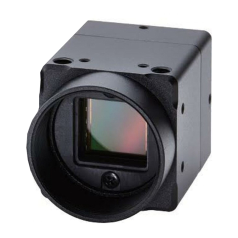
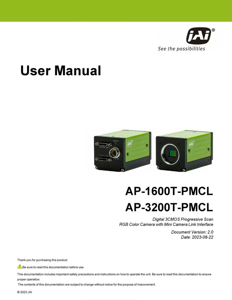
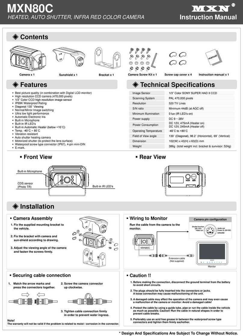
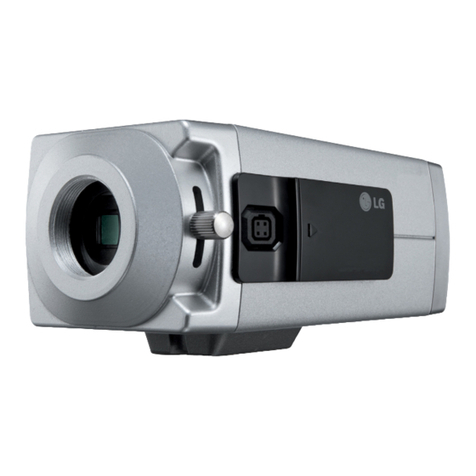
Hi Sharp HS-CX1050 User manual

Thank you for purchasing our product.
Please read this User’s Manual before
using the product. Change without Notice
BOX COLOR CAMERA
Please read before using
1. Please read the service manual in details before using.
2. Don't try to disassemble the chassis or the part easily , in case
that touch the power by mistake , is shocked by electricity the
danger or caused inside parts to be damaged ,
3. Do not attempt to service this unit yourself unless you are
authorized to do so. Opening cover may exposure you to
dangerous voltage or other hazards. Refer all servicing to
qualified personnel only.
4. When being regular, please lock the parts firmly first to prevent
the machine damage.
5. Please connect correctly in accordance with the regulation,
prevent the machine from using, or striking improperly.
6. Please don't use any organic solution or the corrosively sanitizer
to insert and wipe away the chassis outside. While inserting and
wiping away, please turn off the power, and use the clean cloth is
stained with letting a small amount of branch water, insert and
wipe away appearance.
7. Please don't use the camera under the following abominable
environments. Temperature is lower than- 10 degrees
Centigrade, or is higher than +50 degrees Centigrade.
4
SAFETY PRECAUTIONS
CONTENT TABLE
CONTENT TABLE…………………………………………..………………. 2
FCC STATEMENT…………………………………………..………………. 3
SAFETY PRECAUTIONS………………………………………................. 4
REAR PANEL………………………………………………………………… 5
Type A………………………………………………………………………. 5
a. Power Input…………………………………..…………………. 6
b. Switch Control PIN……………………..………………………. 6
Type B………………………………………………………………………. 7
a. Power Input…………………………………..…………………. 8
b. Switch Control PIN……………………..………………………. 8
Type C………………………………………………………………………. 9
a. Power Input…………………………………..…………………. 9
b. Switch Control PIN……………………..………………………. 9
IRIS PIN……………………………..…………………………..................... 10
INSTALL STEP……….. …………………………………………………….. 11
SPECIFICATION.. …….…………………………………………………….. 12
DIMENSION…………………………………………………………………... 13
The lightning flash with arrowhead symbol, within an
equilateral triangle, is intended to alert the user to the
presence of insulated dangerous Voltage within the
product’s enclosure that may be sufficient magnitude
to constitute risk of electrical shock to persons.
The exclamation point within an equilateral triangle is
intended to alert the user to the presence of important
operation and maintenance (servicing) instructions in
the literature accom
p
an
y
in
g
the a
pp
liance.
FCC STATEMENT
WARNING
This device complies with Part 15 FCC Rules. Operation is subject to the
following two conditions:
(1) This device may not cause harmful interference.
(2) This device must accept any interference received including
interference that may cause undesired operation."
* Federal Communications Commission (FCC) Statement
WARNING
This Equipment has been tested and found to comply with the limits for a
Class B digital device, pursuant to Part 15 of the FCC rules. These limits
are designed to provide reasonable protection against harmful interference
in a residential installation. This equipment generates uses and can radiate
radio frequency energy and, if not installed and used in accordance with
the instructions, may cause harmful interference to radio communications.
However, there is no guarantee that interference will not occur in a
particular installation. If this equipment does cause harmful interference to
radio or television reception, which can be determined by turning the
equipment off and on, the ser is encouraged to try to correct the
interference by one or more of the following measures:
- Reorient or relocate the receiving antenna.
- Increase the separation between the equipment and receiver.
- Connect the equipment into an outlet on a circuit different from that to
which the receiver is connected.
- Consult the dealer or an experienced radio/TV technician for help.
* You are cautioned that changes or modifications not expressly approved
by the party responsible for compliance could void your authority to operate
the equipment.
3
2
All manuals and user guides at all-guides.com
all-guides.com

REAR PANEL
Type A
5 6
Video Out
Switch Control
Iris Pi
n
Power Input
Video Out
Switch Control
Iris Pin
Power Input
Audio Out
Without Audio
With Audio
a. Power Input
GND
7 8
Video Out
Switch Control Iris Pin
Power Input
Video Out
Switch Control
Iris Pin
Power Input
Audio Out
Without Audio
With Audio
T
yp
e B
b. Switch Control PIN:
BLC: Backlight Compensation (ON/OFF)
FLK: Flicker less Mode (ON/OFF, Japan)
AGCMAX: Max Auto Gain Control (ON/OFF)
MIR: MIRROR (ON/OFF)
AWB1: Audio White Balance Mode (ON/OFF)
AWB2: Audio White Balance Mode (ON/OFF)
AWB3: Audio White Balance Mode (ON/OFF)
DC: Auto Lens Electronic Control (DC drive)
VIDEO: Auto Lens Signal Control (VIDEO drive)
AES: Auto Electronic Shutter
AWB1 AWB2 AWB3 Mode
OFF OFF OFF Auto Trace White Balance
OFF OFF ON Optional
OFF ON OFF Optional
OFF ON ON Optional
ON OFF OFF White Balance 1
ON OFF ON White Balance 2
ON ON OFF White Balance 3
ON ON ON White Balance 4
a. Power Input
GND
b. Switch Control PIN:
DC: Auto Lens Electronic Control (DC drive)
VIDEO: Auto Lens Signal Control (VIDEO drive)
AES: Auto Electronic Shutter
BLC: Backlight Compensation (ON/OFF)
FLK: Flicker less Mode (ON/OFF, Japan)
DC12V/AC24V
DC12V/AC24V
All manuals and user guides at all-guides.com

SPECIFICATION
INSTALL STEPS
1. Make the camera on the bracket stable.
2. Then connect the 75Ωcoaxial cable to device video in.
3. Put the power cable on.
4. Users may adjust the camera poison and angle in different environment.
11
IRIS PIN:
PIN Video Type DC Type
1 +12V DAMP +
2 NC DAMP -
3 VIDEO DRIVER +
4 GND DRIVER -
Horizontal
Resolution
530 TV Lines 420 TV Lines
Pick up device 1/3” interline transfer CCD
Total Pixels NTSC: 811(H) x 508(V)
PAL: 795(H) x 596(V)
NTSC:537(H) x 505(V)
PAL:537(H) x 597(V)
Effective Pixels
NTSC:768 (H) x 494(V)
PAL:752 (H) x 582 (V)
NTSC:510(H) x 492(V)
PAL:500(H) x 582(V)
Syn. System 2:1 Internal
Scanning System NTSC 525 lines / 60 fields
PAL 625 lines / 50 fields
Video Output 1.0 Vp-p / 75 Ohm composite
Electronic
Shutter Auto 1/60 (1/50)~1/100,000 sec.
Lens Video / DC Lens / AE
S/N Ratio More than 48db (AGC OFF)
Min. Illumination 0.5 Lux / F2.0 0.3 Lux / F2.0
Power Supply DC12V AC24V/DC12V AC 110/220V DC12V AC24V/DC12V AC 110/220V
Current 2W
(Max)
2.5W / 2.8W
(Max)
2.6W / 2.6W
(Max)
1.6W
(Max)
2.1W / 2.4W
(Max)
2.5W / 2.5W
(Max)
Power
Consumption
(Without Lens)
160mA
(Max)
210mA /240mA
(Max)
48mA /24mA
(Max)
130mA
(Max)
170mA /200mA
(Max)
44mA /22mA
(Max)
Dimension 67(W) x 92.5(D) x 58(H)mm
Operating Temp -10 to 50℃(14 to 122℉)
Storage Temp -20 to 70℃(-4 to 158 ℉)
10
TypeA TypeB
Type C
12
a. Power Input
b. Switch Control PIN:
DC: Auto Lens Electronic Control (DC drive)
VIDEO: Auto Lens Signal Control (VIDEO drive)
AES: Auto Electronic Shutter
9
All manuals and user guides at all-guides.com

13
DIMENSION
Type A
Type B
All manuals and user guides at all-guides.com
