Hi-Target Surveying Instrument ZTS-360R User manual

Hi-Target Surveying Instrument Co. Ltd.
NAME: TOTALSTATION
MODEL:ZTS-360R
The statements should be displayed in the user manual:
changes or modifications not expressly approved by the
party responsible for compliance could void the user’s authority
to operate the equipment.
This equipment has been tested and found to comply with
the limits for a Class B digital device, pursuant to Part 15 of the
FCC Rules. These limits are designed to provide reasonable
protection against harmful interference in a residential
installation. This equipment generates, uses and can radiate radio
frequency energy and, if not installed and used in accordance
with the instructions, may cause harmful interference to radio
communications.However, there is no guarantee that interference
will not occur in a particular installation.
If this equipment does cause harmful interference to radio
or television reception, which can be determined by turning the
equipment off and on, the user is encouraged to try to correct the
interference by one or more of the
following measures:
-- Reorient or relocate the receiving antenna.
-- Increase the separation between the equipment and
receiver.
-- Connect the equipment into an outlet on a circuit
different from that to which the receiver is connected.
-- Consult the dealer or an experienced radio/TV technician
for help.

1
Preface
Thank you for purchasing our ZTS-360 Mini series total
station! This manual is your good helper, please read it before
operating the instrument and keep it properly.
Product Validation
In order to get our best service, please give the feedback
about the version, number, purchasing date of the instrument and
your valuable suggestions to us after you purchase our product.
We will attach great importance to every piece of advices
from you!
We will pay much attention to every detail of our products!
We will make great efforts to provide better quality!
Notice: We reserve the right to change the technical
parameters during updating and improving our products and we
may not announce you in advance. The Pictures in this manual is
for reference only, please in kind prevail.

2
Features
Rich Features--our total station carries abundant surveying
application, at the same time has the functions of data storage,
parameter settings and etc. It’s suitable for all kinds of
professional measurements.
Absolute code disc
Equipped with absolute code disc, the instrument can
measure after switched on .Even if reset the battery halfway, the
azimuth information will not be lost.
A high-capacity RAM Management
It serves an easy management for file system, including the
increase, deletion and transmission of data.
Non-prism distance measuring
With non-prism distance measuring, this series total station
can be directly to all kinds of material, different colors of objects
(such as the structure of the walls, poles, wires, cliff wall,
mountain, clay, wood, etc.) for long, fast, high precision
measurement .This function is especially for the measurements
of targets that cannot be accessed.
Special measurement program
Our total station is equipped with some special
measurement program to meet the needs of professional
measuring, such as Remote Height (REM) Measurement, Offset
Measurement, MLM (MLM Measurement), Resection, Area
measurement calculation, Roadway design and staking out.
Changeable eyepiece
As the eyepiece is changeable, it is convenient to be
equipped with diagonal eyepiece, which makes it easy to
observe the zenith direction high-rise buildings

3
Laser plummet
Easy to direct the station point and free station
Notice:
Don’t look directly into the sun with the objective lens;
Do not leave the instrument at extreme temperatures (too
high or too low) or use it when thermal shock;
When you don’t use the instrument, should load it in the
box and place it well-ventilate and dry place,and pay attention to
the shock-proof ,dust-proof and damp-proof;
In order to get good precision, you should leave the
instrument in the box to make it adapt the environment when
there is a great difference in temperature between working
environment and storage environment
The battery should be unloaded and charged once a month
for extending its life. If not ,the instrument will not be used for
a long term.
When transporting the instrument, you should store it in
box and be careful to avoid extrusion, collision and violent
vibration. A soft mat around the boxes is required for
long-distance transport.
When setting the instrument, it’s better to work with
high-quality wooden tripod for stability and measurement
accuracy.
In order to improve the precision of Non-Prism
measurement, please keep the object lens clean. When cleaning
exposed optical devices, please wipe them gently with absorbent
cotton or lens paper only.
After using instrument, please sweep away the surface dust
with flannelette or hairbrush. Do not switch on the device when
it has got wet by rain. Please wipe it dry with clean soft cloth

4
and put it in ventilated place for a period time to make the
equipment fully dry before using and packing.
Please check out that the indicators, functions, power
supply, initial setting and correction parameters of the instrument
meet the requirements before operating.
If discovering the abnormal function of the instrument,
non-professional maintenance personnel are not allowed to
disassemble the instrument without authorization, in case of any
unnecessary damage.
As a safety precaution, do not aim at eyes directly when
using the instrument.
Security Guide
Please pay attention to the following security matters when
using the instrument with non-prism.
Warning:
Total station is equipped with rangefinders with laser level
3R/IIIa,which is recognized by the following logo recognition at
the horizon-axis locking knob” of the instrument, saying “Class
3A Laser Product”. The Total Station is classified as Class 3R
Laser Product and abides by the class of Laser Product
according to IEC Standard Publication 60825-1:2001.
For Class 3R/IIIa Laser Product, its emitted laser with
wavelength between 400nm and 700nm can be at most 5 times
of that of Class 2/II.
Warnings:
Never star at laser beam constantly, it could cause
permanent eye damage.
Precautions:
Do not see directly into laser beams nor point laser to
persons.
The reflected beams is the necessary for the instrument

5
measurement signal.
Warnings:
It’s dangerous to use Class 3R Laser instrument improperly.
Precautions:
In order to avoid causing damage, the proper precautions
should be taken for you and control well the distance (in
accordance with the standard “IEC60825-1:2001”) that may
occur hazards.
The following is the main part of the explanation of the IEC
Standard Publication:
Class 3R Laser Products are used in outdoors and on
building site (with non-prism measurements).
The personnel who are specially trained, qualified and
authenticated are allowed to stall, adjust and operate these laser
instruments.
b. Set up corresponding laser warning signs in the use of
area range.
c. Prevent anyone from looking directly into laser beams or
watching the laser beams with optical device.
d. In order to prevent laser damage to people, the laser
beams should blocked at the end of the working route. In the
limited area (★Hazardous distances) where the laser beams
through ,the laser beams should be terminated when there are
some activities.
e. the route which laser beans through must be set higher or
lower than the sight of people.
f. When the instrument not in use, please make it
safekeeping and storied. Unauthorized person should not use it.
g. To prevent exposure to laser beam accidentally, such as
mirrors, metal surfaces, windows, be careful as the flat surface
of the mirror and concave mirror.

6
*The hazardous distance refers to the maximum distance
which is from beginning of the laser beams to the laser beam
weaken until it does not harm people. The built-in rangefinder
products equipped with Class 3R/IIIa laser whose hazardous
distance is 1000 meters (3300feet),and in the distance, the
strength weakens to a Class 1 laser (sightseeing beam eyes
couldn't hurt).

7
Content
1. Use of instrument.............................................................. 1
2. Names and functions of the components ................. 2
2.1 Names of the components........................................... 2
2.2 The information of the displays................................ 4
2.3 Functional keys under the basic measurement
mode ..................................................................................................... 9
2.3.1 Angle mode (including three pages) .......... 9
2.3.2 Distance measurement mode....................10
2.3.3 Coordinate measurement mode................12
2.3.4 Explanation of saving data ...........................13
2.4 Star key [★] mode ........................................................13
3. Initial setup.......................................................................16
3.1 On & Off ............................................................................16
3.2 Set up the tilt correction of horizontal and
vertical angles..................................................................................16
3.3 Set up the target Type.................................................17
3.4 Set up the Reflecting Prism Constant....................17
3.5 Signal .................................................................................17
3.6 Set up the Atmospheric Correction.......................18
3.6.1 Set up the Atmospheric Correction value
(ppm) directly .......................................................................18
3.6.2 Calculate the Atmospheric Correction out
with temperature and pressure sensor......................19
3.7 The Correction of the Atmospheric refraction
and the Earth Curvature.............................................................19
3.8 Set up the minimum reading of the angle ..........20
3.9 Setup of Automatic Shutdown................................20
3.10 Set rectangle beep.....................................................21
3.11 Set up the Addictive Constant and the

8
Multiplying Constant ....................................................................21
3.12 Selecting Data File.......................................................22
4. Preparations before measurements........................23
4.1 Unpacking and storing instruments......................23
4.2 Set up the instrument.................................................23
4.2.1 Using plummets to center and level (align)
.....................................................................................................23
4.2.2 Using centering device to center...............25
4.3 Loading and unloading of battery..........................26
4.4 Reflecting Prism. ...........................................................27
4.5 Loading and unloading of the pedestal.................27
4.6 Adjusting eyepiece lens of the telescope and
aiming the target............................................................................27
4.7 Entering letters and numbers..................................28
4.9 Notice for using U disk...............................................31
5. Angle mode ........................................................................32
5.1 Save ....................................................................................32
5.2 0set.....................................................................................33
5.3 Hset ....................................................................................33
5.4 Hold ....................................................................................34
5.5 Angle by repetition.......................................................34
5.6 Slope (V%).......................................................................36
5.7 H-Bz....................................................................................36
5.8 L/R......................................................................................37
5.9 V mode...............................................................................37
6. Distance mode ..................................................................38
6.1 Save ....................................................................................38
6.2 Meas...................................................................................38
6.3 Mode...................................................................................39
6.4 Offset..................................................................................39
6.5 Stake out (S.O)................................................................39

9
7. Coordinate mode.............................................................41
8. Offset mode.......................................................................46
8.1 Offset (Angle)..................................................................46
8.2 Offset (Dist1)..................................................................47
8.3 Offset (Dist2)..................................................................49
8.4 Offset (Plane)..................................................................50
8.5 Offset (Column).............................................................52
9. Menu....................................................................................55
9.1 Surveying.........................................................................55
9.1.1 Operation............................................................55
9.1.2 Preparation........................................................56
9.1.2.1 File selection for surveying ......................56
9.1.2.2 Select coordinate file...................................56
9.1.3 Station and backsight.....................................57
9.1.3.1 Example for set station ..............................57
9.1.3.2 Example for setting angle..........................60
9.1.4Measurement.....................................................62
9.2 Staking out.......................................................................63
9.2.1 Staking out points...........................................64
9.2.2 Polar coordinates.............................................67
9.2.3 Resection ............................................................69
9.3 File manager ...................................................................73
9.3.1 File Dialogbox....................................................73
9.3.2 Import..................................................................77
9.3.2.1 Import from PC ............................................77
9.3.2.2 Import from USB .........................................79
9.3.3 Export ..................................................................80
9.3.3.1 Export to PC...................................................81
9.3.3.2 Export to USB................................................82
9.3.3.3 Export with Mini USB port......................83
9.3.4 Format disk........................................................84

10
9.3.5 Information of disk (MenInfo)...................84
9.3.6 Update..................................................................84
9.4 Program............................................................................87
9.4.1 Remote height (REM)....................................87
9.4.1.1 “Input T.H” Mode.........................................87
9.4.1.2 “Without T.H”................................................88
9.4.2 MLM......................................................................90
9.4.3 Coord.Z ................................................................91
9.4.4 Area measurement.........................................93
9.4.5 Projection ...........................................................94
9.4.6 Roadway .............................................................96
9.5 Options..............................................................................96
9.6 Adjust ................................................................................97
9.6.1 Calibrate I.E .......................................................98
9.6.2 Calibrate TILT:X ..............................................98
9.6.3 Calibrate TILT:Y ...........................................100
9.7 Config (Instrument constant) ..............................100
9.8 Select code file..............................................................101
9.9 Gird scale.......................................................................101
9.10 Communication .......................................................102
10. Roadway ....................................................................... 103
10.1 Inputting Roadway .................................................103
10.1.1 Horizontal alignment...............................103
10.1.1.1 Element method .....................................103
10.1.1.2 Intersection method.............................106
10.1.2 Vertical alignment.....................................107
10.2 Stake out (road) .......................................................109
10.2.1 Selecting Roadway File.............................110
10.2.2 Setting station and BBS(backsight point)
..................................................................................................110
10.2.3 Stake out road .............................................110

11
11. Adjustments and Corrections................................ 113
11.1 Tubular Level ............................................................113
11.2 Circular Level............................................................114
11.3 Reticle of the telescope..........................................114
11.4 The Perpendicularity of Collimation axis and
Cross axis (2C) .............................................................................115
11.5 Vertical plate index zero automatic
compensation...............................................................................117
11.6 Vertical index error (angle i) and set vertical
index 0 .............................................................................................118
11.7 Centering device......................................................119
11.8 Addictive constant (K)...........................................120
11.9 The parallelism of collimation axis and
photoelectricity axis ...................................................................121
11.10 Non-prism ranging..............................................122
12. Technical parameters.............................................. 124
Appendix A File format introduction (Sunway)....127
Appendix B Bi-directional communication............. 129

1
1. Use of instrument
The total station is such an instrument that measures the
azimuth and distances to destination and can calculate the
destination point coordinates automatically. It plays an important
role in the economic construction and national defense
construction. General Survey, exploration and mining of
minerals, the construction of railways, roads, bridges, irrigation,
urban planning and construction is driven by electronic total
station measurements. In the building of national defense, such
as battlefield preparations, harbor, forts, airfields, bases and
military construction projects, and so on, must be based on a
detailed and accurate geodetic. In recent years, electronic total
station is a large precision engineering, shipbuilding and aviation
industries and other aspects of effective tools for precise
positioning and installation.
The series total station is equipped with absolute code dial
system, integrated-circuit-control-board ranging item and
microcomputer for measurements of angle and distance and for
calculation, display, depositing and etc. It can exhibit horizontal
and vertical angle, slope and horizontal distance and altitude
difference simultaneously. Furthermore, it can be set to measure
under different mode (e.g. Angle mode, Distance mode).It is
even designed for you specializing in construction projects with
non-prism ranging. The non-prism ranging can be
comprehensively used in measuring three-dimensional
coordinates, position determination, remote elevation
measurement (REM), verticality, pipeline positioning,
cross-section measurement etc. It also meets requirements for
trigonometrical control survey, topographic survey, cadastre and
real estate survey.
2
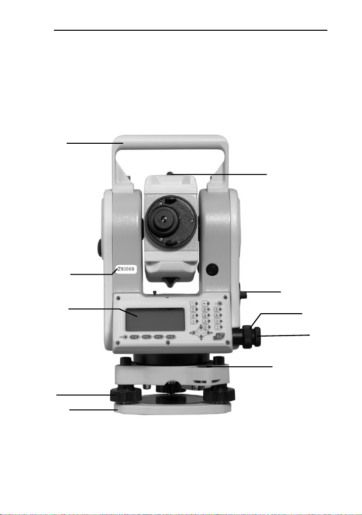
2. Names and functions of the components
2.1 Names of the components
Horizontal
clamping screw
Coarse
sighting device
Number
Display
Battery box
Horizontal
tangent screw
Base
Circular bubble
Handle
Leveling screw

3
Handle
Objective lens
Vertical clamping
screw
Vertical tangent
screw
Display
USB port
Fast measuring key
RS-232
Communication port
Leveling screw
Base

4
2.2 The information of the displays
The sketch of display and keyboard in face left
The sketch of display and keyboard in face right

5
Symbols on the keyboard
Keys
Name
Function
ANG
Angle
measurement
In the basic interface,enter the angle
measurement . Under other modes, move
the cursor up or up to select the options.
DIST
Distance
measurement
In the basic interface,enter the distance
mode;
In the other modes,Move the Cursor down
or down to select the options.
CORD
Coordinate
measurement
In the basic interface,enter the coordinate
mode;
In the other modes, move the cursor left or
page up.
MENU
Menu key
Under the basic measurement interface,
down to the menu interface.
Under the other modes ,move the cursor
right or page down
Power key
Power on/off
F1~F4
Soft Keys
The characters at the bottom line of the
display indicate the meaning of the soft
keys.
0~9
Number keys
Input numbers or characters or choose the
menu
★
Star key
In any measurement interface, you can
enter the star key interface .You can set the
contrast, lighting compensator , parameters
of distance measuring and file
selecting .etc.
The side
key
Enter
Receive and save the data input in the
dialogue and end the dialogue.
Save the current measurement data under

6
the basic measurement interface.
ESC
Exit /quit
End the dialogue box without saving the
input,and return to the previous step
◄►
Left /right
change the option in the select box
Data list page
▲▼
Up /down
Move the Cursor up and down in order.
Turn the page under the basic measurement.
0~9
Number
Input number and characters and select one
of menu.
“0”: Enter the electronic bubble interface
under the basic measurement.
·~ -
Symbols
Enter symbols, decimals and signs;
Enter the interface for input height.
The side
key
Fast
measurement
key
This function is equal with it of the key
[MSR1]. It works just in the measurement
interface, and does not work in the others.
Symbols on the display
Symbols
Indication
Vz
Zenith Mode
Vo
The mode that the vertical is displayed as zero when the
telescope is level in normal
Vh
Vertical angle Mode (it is 0°00′00″when the telescope is
level. The angle of elevation is positive and the angle of
depression is negative.)
V%
Slope Mode
HR
Horizontal angle (right angle). dHR means the angle
difference of setting out.
HL
Horizontal angle (anticlockwise increment)
HD
Horizontal distance. dHD is to stake out horizontal

7
distance difference.
VD
Elevation difference. dVD is to stake out difference
between elevation differences.
SD
Slope distance. dSD is to stake out differences between
slope distances.
N
Northing. dN is to stake out differences between
north-coordinates.
E
Easting. dE is to stake out differences between
East-coordinates.
Z
Elevation. dZ is to stake out differences between
Z-coordinates
EDM(Electronic Distance Measurement) is in progress.
m
Unit in meters (metric units)
ft
Units in feet
fi
Units in American feet
M
Units inMIL
X
The magnitude of which is along the baseline in a point
projection measurement. The positive direction is from the
starting point to the terminal.
Y
The magnitude of which deviates from the base line
horizontally in a point projection measurement.
Z
Altitude of the target in a point projection measurement.
MdHD
Maximum error of evaluated distance
Reference functions of common soft key
Soft key
reference
Functions
B.S
(Backspace)Delete one last character on the left of
the inserter in the edited column.
Clear
Delete all typed in the edited column.
Enter
End up the input in the current edited column and the

8
inserter goes to the next column. If there’s only one
or no edited column in the dialogue box, the soft key
‘Enter’ is also used to accept the input and exit the
dialogue box.
Input
Go to Coordinate dialogue box and enter the
coordinates with keyboard
M.Pt
Retrieval coordinates of points from measured file
K.Pt (Known)
call coordinates of points from coordinate file
Search
List the points in the current coordinate file to
provide to select the number for you.
View
List out details of the current record
Info.
Displays the name, code and coordinate of the
current station and back-sight station.
Settings
Set the height of the instrument and the target
STA
Enter coordinates of the station where instrument is
placed.
BBS
Enter coordinates of the point where the target is.
Meas
Start rangefinders to measure distance
Save
Start rangefinders when being under the Coordinate
and Distance mode. Then save the result of this
measurement and name of point which is added by
one automatically. The result cannot be saved when
the compensator is over .(Tilt over)
Comp.
Display the inclination (tilt) of the vertical axis
Light
Turn on or off the backlight and the illuminating
brightness of reticle (at the same time).
Para.
Set the atmospheric parameters, prism constant and
signals.
Table of contents


