Kenko KFM-2100 User manual

FLASH
MET
KFM-2
1
INSTRUCTION
MANUAL
5
ISO
LATITUDE
MODE
CLR
S/AlH
MEMORY
Instruction
Manual
FLASH
METER
KFM-2100
The
Kenko
Flash
Meter
KFM-2100
has
the
following
features:
@The
integrated
exposure
meter
combines
incident
light
measurement
and
spot
(reflected
light)
measurement
in
a
single
unit.
@For
spot
measurement,
the
Flash
Meter
KFM-2100
uses
a
parallax-free
optical
system.
This
eliminates
the
displacement
of
the
measurement
area
that
varies
with
the
distance
from
the
subject.
@With
the
latitude
display
function,
the
Flash
Meter
KFM-2
100
сап
simultaneously
display
the
results
of
both
incident
light
measurement
and
spot
light
measurement.
It
provides
a
clear
and
simple
graphical
decision
process
for
determining
the
exposure
suited
to
the
nature
of
the
photograph.
@With
the
analyze
scale,
you
can
determine
the
proportion
of flash
light
and
ambient
light
in
a
single
flash
light
measurement.
@The
Flash
Meter
KFM-2100
provides
a
memory
function
capable
of
storing
up
to
10
measured
values;
an
averaging
function
that
calculates
an
average
exposure
from
stored
measurement
data;
and
a
brightness
difference
function
that
displays
deviation
from
the
standard
exposure.
@For
spot
measurement,
both
shadow-based
and
highlight-based
exposure
calculation
functions
are
provided.
Q
The
Flash
Meter
KFM-2100
provides
a
"custom
setting
(Alt)
mode"
that
allows
you
tocustomize
the
meter
according
to
your
preference.
This
feature
includes
an
exposure
correction
value
setting
function
and
a
shutter
speed
increment-setting
function.
©
Measurement
results
are
shown
on
both
the
analog
and
digital
displays
on
the
meter's
data
panel.
The
clear
and
legible
display
eliminates
reading
errors.
@The
results
of
spot
measurements
are
shown
on
the
digital
display
in
the
viewfinder
and
on
the
external
data
panel.
The
viewfinder
features
a
dioptric
adjustment
mechanism.
Qn
addition
to
displaying
a
conventional
10-level
intermediate
f-number
display,
the
Flash
Meter
KFM-2
100
provides
an
f-number
direct
reading
display.
This
enables
the
measured
value
to
be
applied
to
any
camera
with
an
fnumber
direct
reading
display,
eliminating
the
need
for
f-number
conversion.
Kenko
CO.,LTD.
^
Tokyo
Japan
2
Names
of
Parts
and
Displays
@Data
panel
displays
@Viewfinder
display
Preparations
-------
@Battery
----
1.Preparing
2.Inserting
3.Checking
@Setting
film
speed
---
@Setting
instant
film
speed
for
test
shooting
G
Selecting
a
measuring
method
suitable
for
the
light-receiving
method
·
·
T.Incident
light
measurement:
2.Spot
measurement
·
-
*Difference
between
incidentJight
and
Spot
(reflected-light)
readings
----11
Basic
Орегаһоп:““%“:-:-%:5:5:%55555555555-.-..1
1666666.
6Ш
өн нн
Т.
@Select
а
measuring
method
@Measuring
ambient
light
---
1.With
a
still
camera
-----
2.
With
a
cine
camera
·
-
G
Measuring
flash
light
--
6
6
XX
XXX
1.With
an
over-the-counter
sync
cord
«88
16
2.
Without
an
over-the-counter
sync
cord
(Incident
light
measurement)
--19
*Light
Ratio
Analyze
function
:«:-:e
66е
21
Special
Functions
@
Latitude
display
function
se
*Combining
incident
light
measurement
and
spot
measurement
-
GO
Memory
function
*:
е
MOS.
@S/A/H
(Shadow/Average/Highlight)
calculations
G
Brightness
difference
function
G
Measuring
lighting
ratio
using
the
Flat
Diffuser
Q9
Using
the
KFM-2100
as
a
simplified
illuminance
meter
--
-
Q
Using
the
KFM-2100
as
a
simplified
luminance
meter
G
Custom
settings
mode
(Alt
mode)
>----------------
4...
0).
Accessories
Care
and
Storage
-
1.
Care
---
2.
Storage
····
Handling
Instructions
+++
Specifications
:«««
ееееееееееееееее
еее
еее
еее
еее
nnne

The
following
icons
are
used
in
this
manual
to
alert
you
to
important
information
for
preventing
accidents
due
to
improper
handling
of
the
instrument.
This
indicates
a
danger
that
improper
use
of
A
WARNING
the
instrument
will
read
to
the
death
or
serious
injury
of
the
user.
This
indicates
a
danger
that
improper
use
CAUTION
of
the
instrument
will
lead
to
the
injury
to
the
user
or
to
property
damage.
This
denotes
actions
to
be
strictly
&
PROHIBITION
avices.
Make
sure
to
avoid
these
actions.
This
denotes
actions
to
be
avoided.
®
RPOHIBITION
Do
not
attempt
to
disassemble
the
product.
To
ensure
proper
use
of
the
instrument,
take
special
care
to
observe
the
following
handling
instructions
when
using
this
instrument.
Read
this
instruction
manual
carefully
and
keep
it
securely
in
a
place
where
you
can
refer
to
it
readily.
WARNING
Do
not
use
the
instrument
in
a
place
where
inflammable
or
combustible
vapors
(e.g.
gasoline)
are
present.
Otherwise
there
is
a
risk
of
causing
a
fire.
Do
not
throw
batteries
into
fire.
Do
not
recharge
(nonrechargeable
batteries),
short
circuit,
heat
or
disassemble
batteries.
Otherwise,
there
is
a
risk
of
causing
fire
or
injury
due
to
an
explosion
or
fluid
leakage.
ООР
Never
attempt
to
disassemble
ог
modify
the
instrument
yourself.
Otherwise
there
is
a
risk
of
causing
fire
or
electric
shock.
Never
attempt
to
look
directly
at
the
sun
through
the
viewfinder
of
the
instrument.
Doing
so
will
damage
your
eyesight.
The
instrument
should
not
be
operated
if
it
is
damaged,
or
smoke
or
odd
smells
occur.
Doing
so
may
result
in
a
fire.
In
such
situations
turn
off
the
power
immediately,
disconnect
the
AC
adapter,
and
contact
the
nearest
authorized
service
facility
for
repair.
CAUTION
Do
not
use
any
batteries
other
than
those
designated
for
use
with
the
instrument.
When
fitting
batteries,
make
sure
to
align
them
according
to
the
polarity
shown
on
the
instrument
(plus
"+"
and
minus
"—").
Otherwise
there
is
a
risk
that
the
batteries
may
leak
or
become
damaged,
leading
to
fire,
injury
or
pollution
of
the
surrounding
environment.
Do
not
walk
around
while
looking
into
the
viewfinder.
Doing
so
may
result
in
a
fall
or
other
accident.
OP
ooe
Keep
the
instrument
out
of
reach
of
children.
Fall
of
the
instrument
may
cause
injury,
and
twining
of
the
strap
around
the
neck
can
cause
suffocation.
STATEMENT
OF
FCC
COMPLIANCE
This
equipment
has
been
tested
and
found
to
comply
with
the
limits
for
a
Class
B
digital
device,
pursuant
to
Part
15
of
the
FCC
Rules.
These
limits
are
designed
to
provide
reasonable
protection
against
harmful
interference
in
a
residential
installation.
This
equipment
generates,
uses
and
can
radiate
radio
frequency
energy
and,
if
not
installed
and
used
in
accordance
with
the
instructions,
may
cause
harmful
interference
to
radio
communications.
However,
there
is
no
guarantee
that
interference
will
not
occur
in
a
particular
installation.
If
this
equipment
does
cause
harmful
interference
to
radio
or
television
reception,
which
can
be
determined
by
turning
the
equipment
off
and
on,
the
user
is
encouraged
to
try
to
correct
the
interference
by
one
or
more
of
the
following
measures:
@Reorient
or
relocate
the
receiving
antenna.
@Increase
the
separation
between
the
equipment
and
receiver.
G
Connect
the
equipment
into
an
outlet
on
a
circuit
different
from
that
to
which
the
receiver
is
connected.
G
Consult
the
dealer
or
an
experienced
radio/TV
technician
for
help.
This
Class
B
digital
apparatus
complies
with
Canadian
ІСЕ5-003.
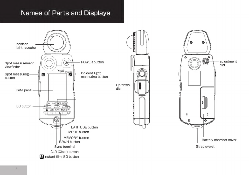
Names
of
Parts
and
Displays
Incident
light
receptor
adjustment
dial
Spot
measurement
POWER
button
viewfinder
a
Ке
5 :
EN
Spot
measuring
r
Ed
Incident
light
button
measuring
button
Up/down
dial
ISO
LATITUDE
MODE
ISO
button
0
||
CLR
S/A/H
MEMORY]
SEV]
LATITUDE
button
MODE
button
MEMORY
button
S/A/H
button
Sync
terminal
Strap
eyelet
CLR
(Clear)
button
©)
Instant
film
ISO
button
Battery
chamber
cover

Data
panel
displays
1.
Analog
scale
status
indicator
4.
Measurement
data
status
indicator
інін
"101
15
TIME
CINEmsf/s
(eiii
ІШЦІТІ
i—
5.
S/A/H
indicator
—
6.
@
indicator
Pointers
——-
3.
Analog
scale
R
2.
Analog
scale
L
For
the
purpose
of
explanation,
the
diagram
above
shows
al
indicators
that
light
up
on
the
LCD.
Names
of
Parts
and
Displays
T.Analog
scale
status
indicator
The
left
(L)
and
right
(R)
analog
scales
are
used
for
incident
light
measurement
and
spot
measurement,
respectively.
2.Analog
scale
L
The
display
of
the
pointers
corresponds
to
measurement
data
and
memory
data
for
incident
light
measurement.
It
also
corresponds
to
the
standard
exposure
or
latitude
for
incident
light
measurement
or
spot
measurement.
The
small
digit
to
the
right
of
the
two-digit
22
reading
(f-number)
on
the
digital
16
readoutindicates
a
fractional
value
Upper
limit
11
between
stops.
The
value
shown
on
the
=
analog
display
is
rounded
down
or
up
to
8
the
nearest
0.5
stops.
(Values
of
0.2
or
Standard
—
—me
5.6
lower
are
rounded
down
to
O;
those
of
0.3
value
4
to
O.7
are
rounded
to
0.5;
and
those
of
=
0.8
or
greater
are
rounded
up
to
1.)
Lower
limit
28
When
a
latitude
range
is
indicated,
all
dots
2
between
the
upper
and
lower
limits
are
lit.
14
3.Analog
scale
R
The
display
of
the
pointers
corresponds
to
measurement
data
and
memory
data
for
spot
measurement.
The
small
digit
to
the
right
of
the
two-digit
reading
(f-number)
on
the
digita
readout
indicates
a
fractional
value
between
stops.
The
value
shown
on
the
analog
display
is
rounded
down
or
up
to
the
nearest
O.5
stops.
(Values
of
0.2
or
lower
are
rounded
down
to
O;
those
of
0.3
to
0.7
are
rounded
to
0.5;
and
those
of
0.8
or
greater
are
rounded
up
to
1.)
4.Measurement
data
status
indicator
When
a
value
measured
with
incident
light
measurement
is
displayed,
the
indicator
appears.
When
a
value
measured
with
spot
measurement
is
displayed,
the
indicator
appears.
5.S/A/H
indicator
Holding
down
the
S/A/H
button
while
a
measured
value
is
displayed
lights
the
S,
A
or
H
indicator
corresponding
to
the
currently
selected
AG
mode.
6.
ЄЗ
indicator
This
indicator
turns
on
when
the
LATITUDE
button
is
pressed.
Names
of
Parts
and
Displays
De
о
о
Ac
f608440444544444444444411»?
A
>
сл
--
7.
Digital
readout
со
n»
R
a
-
т»
=
[x
peu
=
—
C»
TIME
CINEmsf/s
‘|
—
8.
Shutter
speed/
|
(Гі
ГІ ГІ
ГІ
|
framingrate
display
(LILI
GG
LG
ET
о
—
9.
Analyze
scale
—
1О.Навһ
light
measuring
indicator
ғо
мэ чь
сл
со
со
I—
11.Film
speed
display
=
>
A
a
e|
I—
12.Measuring
mode
display
POs
For
the
purpose
of
explanation,
the
diagram
above
shows
all
indicators
that
light
up
on
the
LCD.
6
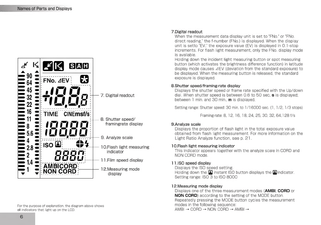
7.Digital
readout
When
the
measurement
data
display
unit
is
set
to
"FNo."
or
"FNo.
direct
reading,"
the
f-number
(FNo.)
is
displayed.
When
the
display
unit
is
setto
"EV,"
the
exposure
value
(EV)
is
displayed
in
O.1-stop
increments.
For
flash
light
measurement,
only
the
FNo.
display
mode
is
available.
Holding
down
the
incident
light
measuring
button
or
spot
measuring
button
(which
activates
the
brightness
difference
function)
in
latitude
display
mode
causes
AEV
(deviation
from
the
standard
exposure)
to
be
displayed.
When
the
measuring
button
is
released,
the
standard
exposure
is
displayed.
8.Shutter
speed/framing-rate
display
Displays
the
shutter
speed
or
frame
rate
specified
with
the
Up/down
dial.
When
shutter
speed
is
between
O.6
to
50
sec,
s
is
displayed;
between
1
min.
and
30
min.,
m
is
displayed.
Setting
range:
Shutter
speed:
30
min.
to
1/16000
sec.
(1,
1/2,
1/3
stops)
Framing-rate:
8,
12, 16,
18,
24,
25, 30,
32,
64,128
f/s
9.Analyze
scale
Displays
the
proportion
of
flash
light
in
the
total
exposure
value
obtained
from
flash
light
measurement.
For
more
information
on
the
Light
Ratio
Analyze
function,
see
p.
21.
10.Flash
light
measuring
indicator
This
indicator
appears
together
with
the
analyze
scale
in
CORD
and
NON
CORD
mode.
11.180
speed
display
Displays
the
ISO
speed
setting.
Holding
down
the
@)
instant
ISO
button
displays
the
[gJindicator.
Setting
range:
ISO
3
to
ISO
8000
12.Measuring
mode
display
Displays
one
of
the
three
measurement
modes
(AMBI,
CORD
or
NON
CORD)
according
to
the
setting
of
the
MODE
button.
Repeatedly
pressing
the
MODE
button
cycles
the
measurement
modes
in
the
following
sequence:
AMBI
+
CORD
>
NON
CORD
>
AMBI
>
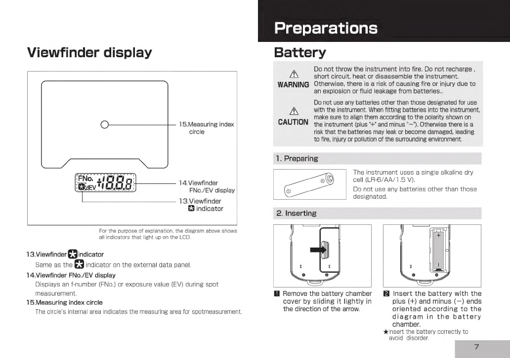
Viewfinder
display
15.Measuring
index
circle
14.Viewfinder
FNo./EV
display
13.Viewfinder
indicator
For
the
purpose
of
explanation,
the
diagram
above
shows
all
indicators
that
light
up
on
the
LCD.
13.Viewfinder
indicator
Same
as
the
indicator
on
the
external
data
panel.
14.Viewfinder
FNo./EV
display
Displays
an
f-number
(FNo.)
or
exposure
value
(EV)
during
spot
measurement.
15.Measuring
index
circle
The
circle's
internal
area
indicates
the
measuring
area
for
spotmeasurement.
Preparations
Battery
Do
not
throw
the
instrument
into
fire.
Do
not
recharge
,
AN
short
circuit,
heat
or
disassemble
the
instrument.
WARNING
Otherwise,
there
is
a
risk
of
causing
fire
or
injury
due
to
an
explosion
or
fluid
leakage
from
batteries..
Do
not
use
any
batteries
other
than
those
designated
for
use
AN
with
the
instrument.
When
fitting
batteries
into
the
instrument,
make
sure
to
align
them
according
to
the
polarity
shown
on
CAUTION
the
instrument
(plus
"+"
and
minus
"—").
Otherwise
there
is
a
risk
that
the
batteries
may
leak
or
become
damaged,
leading
to
fire,
injury
or
pollution
of
the
surrounding
environment.
1.
Preparing
2.
Inserting
The
instrument
uses
a
single
alkaline
dry
cell
(LR-6/AA/1.5
V).
Do
not
use
any
batteries
other
than
those
designated.
Remove
the
battery
chamber
Insert
the
battery
with
the
cover
by
sliding
it
lightly
in
plus
(+)
and
minus
(—)
ends
the
direction
of
the
arrow.
oriented
according
to
the
diagram
in
the
battery
chamber.
insert
the
battery
correctly
to
avoid
disorder.
Preparations
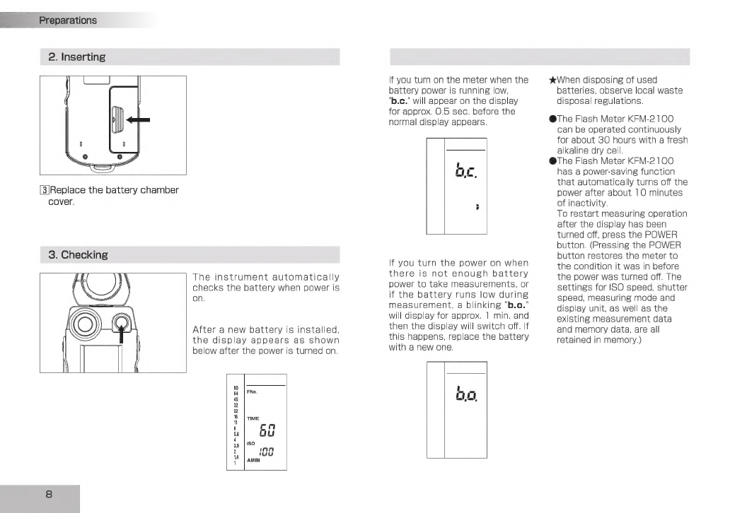
2.
Inserting
[3|Replace
the
battery
chamber
cover.
3.
Checking
The
instrument
automatically
checks
the
battery
when
power
is
on.
After
a
new
battery
is
installed,
the
display
appears
as
shown
below
after
the
power
is
turned
on.
в
|
FNo.
5
|
пме
ca
ca
28
|150
55
сэ
АМВІ
If
you
turn
on
the
meter
when
the
battery
power
is
running
low,
"b.c."
will
appear
on
the
display
for
approx.
O.5
sec.
before
the
normal
display
appears.
If
you
turn
the
power
on
when
there
is
not
enough
battery
power
to
take
measurements,
or
if
the
battery
runs
low
during
measurement,
a
blinking
'b.o."
will
display
for
approx.
1
min.
and
then
the
display
will
switch
off.
If
this
happens,
replace
the
battery
with
a
new
one.
mc
m
*
When
disposing
of
used
batteries,
observe
local
waste
disposal
regulations.
The
Flash
Meter
КЕМ-2100
can
be
operated
continuously
or
about
30
hours
with
a
fresh
kaline
dry
cell.
he
Flash
Meter
KFM-2
100
has
a
power-saving
function
hat
automatically
turns
off
the
power
after about
1O
minutes
of
inactivity.
To
restart
measuring
operation
after
the
display
has
been
urned
off,
press
the
POWER
button.
(Pressing
the
POWER
button
restores
the
meter
to
he
condition
it
was
in
before
he
power
was
turned
off.
The
settings
for
ISO
speed,
shutter
speed,
measuring
mode
and
display
unit,
as
well
as
the
existing
measurement
data
and
memory
data,
are
all
retained
in
memory.)
odo

Setting
ISO
speed
Specify
a
film
speed
with
the
Up/down
dial
while
holding
down
the
ISO
button.
<0
0
6
092
89
кемолоо
ISO
LATITUDE
MODE
E]
CLR
ЗАН
MEMORY
V9
Q
Turning
the
control
upward
increases
the
film
speed
in
increments
of
1/3-stop.
The
maximum
film
speed
is
ISO
8000.
Q
Turning
the
control
downward
owers
the
film
speed
in
decrements
of
1/3-stop.
The
minimum
film
speed
is
ISO
3.
@Be
sure
to
set
ISO
speed
to
the
correct
setting,
since
all
measurement
results
are
based
on
the
set
value.
ФІ?
you
change
the ISO
speed
after
you
take
a
measurement,
he
reading
will
be
recalculated
and
displayed
accordingly.
Preparations
m"
Instant
film
speed
for
test
shooting
can
be
set.
In
film
shooting,
if
the
film
speed
setting
used
for
the
final
shooting
is
different
from
the
instant
film
speed
setting
used
for
test
shooting,
the
instant
film
speed
can
be
registered
in
the
instrument
in
advance.
Once
an
instant
film
speed
is
registered
for
test
shooting,
the
meter
converts
the
measurement
result
into
a
value
based
on
this
setting
when
the
(2)
instant
film
ISO
button
is
pressed
after
measurement.
Specify
an
instant
film
speed
with
the
up/down
dial
while
holding
down
the
(2)
instant
film
ISO
button.
@Turning
the
control
upward
increases
the
film
speed
in
increments
of
1/3-stop.
The
maximum
film
speed
is
ISO
8000.
Qe
Turning
the
control
downward
lowers
the
film
speed
in
decrements
of
1/3-stop.
The
minimum
film
speed
is
ISO
3.
|
"y
Qf
you
change
the
instant
film
speed
after
you
take
a
measurement,
the
reading
will
be
recalculated
and
displayed
180
LATITUDE
MODE
Я
«C2
C5
CJ
accordingly.
|І
CLR
ЗАН
MEMORY

Preparations
Selecting
a
measuring
method
suitable
for
the
light-receiving
method
Select
a
measuring
method,
either
incident
light
measurement
or
spot
measurement,
appropriate
to
the
shooting
conditions
and
nature
of
the
photograph.
The
Kenko
Flash
Meter
KFM-2100
can
measure
exposure
in
either
way.
1.
Incident
light
measurement
When
performing
incident
light
measurements,
use
the
Spherical
Diffuser
for
three-dimensional
subjects
such
as
portraits,
and
architectural
or
landscape
photographs.
Use
the
Flat
Diffuser
when
you
photograph
flat
surfaces
such
as
documents
or
paintings,
or
when
you
want
to
measure
lighting
ratio
(See
page
32).
Attaching
the
Spherical
Diffuser
Removing
the
Spherical
Diffuser
Rotate
the
diffuser
anticlockwise
until
it
stops,
and
pull
the
diffuserto
detach
it.
Align
the
index
mark
(white
circle)
of
the
Spherical
Diffuser
with
theindex
of
the
receptor
head.
Securethe
diffuser
by
turning
it
in
the
direction
indicated
by
the
arrow
until
it
stops.
To
take
an
incident
light
measurement,
position
the
meter
near
the
subject
and
aim
the
Spherical
Diffuser
directly
at
the
camera.
Q
The
receptor
can
rotate
through
a
range
of
270
degrees,
so
that
you
can
use
the
meter
in
an
almost
any
photographic
configuration.
10
AN
Never
attempt
to
look
directly
at
the
sun
through
the
viewfinder
of
the
instrument.
Doing
so
will
damage
your
WARNING
eyesight.
AN
Do
not
walk
around
while
looking
into
the
viewfinder.
CAUTION
Doing
so
may
result
in
a
fall
or
other
accident.
2.
Spot
measurement
To
measure
a
specific
area
of
a
photographic
image,
select
the
spot
measurement
method
(with
a
light-receiving
angle
of
1
degree).
To
take
a
spot
measurement,
ККЕ
А
@position
the
meter
near
the
camera,
Measuring
index
circle
Ф
оок
into
the
viewfinder
at
the
front
of
the
instrument
(data
panel
side),
@locate
the
measuring
index
(circle)
at
the
center
of
the
viewfinder
within
the
desired
measuring
point
of
the
subject,
and
@press
the
spot
measuring
button.
FN
The
allowable
measuring
distance
from
the
subject
is
1.3
m
to
infinity
(оо).
To
stabilize
your
shooting
posture
and
avoid
shaking
the
meter,
turn
the
receptor
head
toward
the
subject
and
hold
the
meter
by
placing
your
hand
over
it
as
shown
above.
Dioptric
adjustment
While
looking
into
the
viewfinder
for
a
spot
measurement,
adjust
the
dioptric
by
turning
the
dioptric
adjustment
dial
until
the
measuring
index
circle
can
be
clearly
seen.
Difference
between
incident-light
and
Spot
(reflected-light)
readings
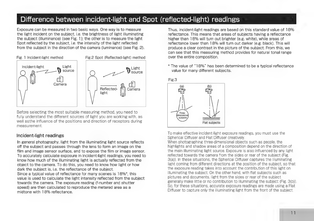
Exposure
can
be
measured
in
two
basic
ways.
One
way
is
to
measure
the
light
incident
on
the
subject,
i.e.
the
brightness
of
light
illuminating
the
subject
(illuminance)
(see
Fig.
1);
the
other
is
to
measure
the
light
Spot
reflected
by
the
subject,
i.e.
the
intensity
of
the
light
reflected
from
the
subject
in
the
direction
of
the
camera
(luminance)
(see
Fig.
2).
Fig.
1
Incident-light
method
Fig.2
Spot
(Reflected-light)
method
Incident-light
y
Light
D
Light
(Ib
—
Z—
y
source
source
a
wae
=
Camera
ђ
Reflected-
light
Before
selecting
the
most
suitable
measuring
method,
you
need
to
fully
understand
the
different
sources
of
light
you
are
working
with,
as
well
asthe
influence
of
the
positions
and
direction
of
receptors
during
measurement.
Incident-light
readings
In
general
photography,
light
from
the
illuminating
light
source
reflects
off
the
subject
and
passes
through
the
lens
to
form
an
image
on
the
film
and
image
sensor
surface,
and
to
expose
the
film
or
image
sensor.
To
accurately
calculate
exposure
in
incident-light
readings,
you
need
to
know
how
much
of
the
illuminating
light
is
actually
reflected
from
the
object
to
the
camera.
To
do
this,
you
need
to
know
how
light
or
how
dark
the
subject
is,
i.e.
the
reflectance
of
the
subject.
Since
a
typical
value
of
reflectance
for
many
scenes
is
1896*,
this
value
is
used
to
calculate
the
light
intensity
reflected
from
the
subject
towards
the
camera.
The
exposure
reading
(f-number
and
shutter
speed)
are
then
calculated
to
reproduce
the
metered
area
as
a
midtone
with
18%
reflectance.
Thus,
incident-light
readings
are
based
on
this
standard
value
of
18%
reflectance.
This
means
that
areas
of
subjects
having
a
reflectance
higher
than
18%
will
turn
out
brighter
(e.g.
white),
while
areas
of
reflectance
lower
than
18%
will
turn
out
darker
(e.g.
black).
This
will
produce
a
clear
contrast
in
the
picture
of
the
subject.
From
this,
we
can
see
that
this
measuring
method
provides
for
natural
tonal
range
over
the
entire
composition.
*
The
value
of
"1896"
has
been
determined
to
be
a
typical
reflectance
value
for
many
different
subjects.
Fig.3
—
f
Three
(dimensional
subjects.
А
Flat
subjects
To
make
effective
incident-light
exposure
readings,
you
must
use
the
Spherical
Diffuser
and
Flat
Diffuser
creatively.
When
photographing
three-dimensional
objects
such
as
people,
the
highlights
and
shadow
areas
of
a
composition
depend
on
the
direction
of
he
main
illuminating
light
source.
Exposure
is
also
influenced
by
any
light
reflected
towards
the
camera
from
the
sides
or
rear
of
the
subject
(Fig.
3(8)).
In
these
situations,
the
Spherical
Diffuser
captures
the
illuminating
ight
coming
from
different
directions
at
he
exposure
reading
takes
into
accoun
So,
for
these
situations,
accurate
expos
Diffuser
to
capture
only
the
illuminating
the
position
of
the
subject,
so
that
the
contribution
of
this
light
on
illuminating
the
subject.
On
the
other
hand,
with
flat
subjects
such
as
pictures
and
documents,
light
from
the
sides
or
rear
of
the
subject
generally
make
little
or
no
contribution
to
illuminating
the
subject
(Fig.
3(b)).
ure
readings
are
made
using
a
Flat
ight
from
the
front
of
the
subject.
11

Preparations
Basic
Operation
Spot
(reflected-light)
readings
Here
we
explain
the
basics
of
using
the
instrument
to
take
exposure
readings
Spot
(reflected-light)
exposure
readings
directly
measure
he
amount
of
light
(luminance)
reflected
from
the
subject
Select
a
measuring
method
o
the
camera.
Unlike
the
case
of
incident-light
readings,
his
method
does
not
rely
on
the
assumption
of
a
standard
@Flash
light
refers
to
artificial
momentary
lighting
from
light
sources
subject
reflectance
of
1896.
Based
on
the
measured
suchas
electronic
flashes,
strobe
flashes,
and
speed
lights.
amount
of
light
falling
on
the
subject,
the
meter
calculates
G
Ambient
light
refers
to
continuous
lighting
from
sources
such
as
he
appropriate
exposure
value
for
reproducing
the
subject
on
film
at
a
suitable
medium
density
(midtone).
This
means
hat
in
Spot
(reflected-light)
readings,
all
subjects,
naturallight
(sunlight)
and
electric
lights
(including
fluorescent
lights).
Qn
either
case,
both
incident-light
exposure
readings
and
spot-light
regardless
of
their
reflectance,
i.e.
regardless
of
whether
exposure
readings
can
be
made.
hey
are
bright
or
dark
(white
or
black),
will
be
reproduced
at
G
When
measuring
flash
light
in
the
CORD
mode,
use
a
commercially
he
same
tonal
density
(midtone).
For
this
reason,
when
available
sync
cord.
making
Spot
(reflected-light)
exposure
readings,
it
is
- -
important
to
decide
which
area
of
the
subject
to
measure,
Are
you
using
a
still
camera?
since
the
reflectance
will
generally
vary
quite
widely
over
the
Are
you
using
a
cine
camera?
composition
under
different
conditions.
With
a
cine
camera
There
are
various
advanced
Spot
(reflected-light)
readings,
such
as
the
highlight
standard
exposure
method,
where
an
exposure
reading
is
taken
of
a
bright
Alt
mode
4
Alt
mode
4
(white)
part
of
the
composition;
the
shadow
standard
exposure
method,
where
a
dark
(black)
part
of
the
МЕН
Select
CINE
(p.39)
composition
is
measured;
and
a
method
for
determining
14
exposure
by
evaluating
the
contrast
of
the
subject
and
then
forecasting
how
it
will
come
out
on
film.
To
make
full
Type
of
light
source
to
measure
use
of
Spot
(reflected-light)
readings,
refer
to
specialist
i
i
books
and
photo
magazines.
You
will
find
that
selective
Ambient
Flash
light
metering
can
give
you
very
precise
control
over
exposure.
fight
(mixed
light)
{
Are
you
using
an
over-the-
counter
sync
cord
?
i
With
a
sync,
Without
a
cord
$
n
AMBI
CORD
NON
CORD
AMBI
mode
mode mode
mode
12
(0.13)
(p.16)
(p.19) (p.15)

Measuring
ambient
light
1.
With
a
still
camera
Basic
Operation
>
to
be
continued
оп
the
next
page
Insert
a
battery
(p.7)
{
Set
ISO
speed
(p.9)
Prepare
the
instrument
to
start
taking
readings.
Ox
(JJ
LA
E
—
Xe
uus
1
‘|
==>
||
g
gj
«==
c
Е
В
=
2
2
ға
ІШ
CLR
БАН
MENORY
)
2
Шар
©
C27
S
ve
Ec
cs
88
$8
ISO
LATITUDE
MODE
a5
1S0
LATITUDE
MODE
58
эсу
у
aa
|
O
С
o
||
ЕЕ
Press
the
MODE
button
to
switch
the
mode
display
to
AMBI.
@Changing
the
measuring
mode
retains
the
memory
data
but
clears
previous
measurement
data.
ElSpecify
the
desired
shutter
speed
with
the
up/down
dial.
Q
Shutter
speed
can
be
set
within
the
range
of
30
min.
to
1/16000
sec.
@Turning
the
up/down
dial
upward
increases
the
shutter
speed.
Turning
it
downward
lowers
the
shutter
speed.
@The
shutter
speed
can
also
be
changed
after
meter
readings.
ІҢ
Press
the
measuring
button
to
take
readings.
Өтпе
meter
takes
measurements
continuously
as
you
hold
down
the
incident
light
measuring
button.
The
igital
display
on
the
data
panel
isplays
the
measurement
data.
At
the
ame
time,
the
measurement
data
are
so
displayed
on
the dot
indicator
of
he
analog
scale
L.
hen
the
measuring
button
is
released,
the
meter
stops
taking
measurements
and
displays
only
the
latest
measurement
result.
Q
The
meter
takes
measurements
continuously
as
you
hold
down
the
spot
measuring
button.
The
digital
display
in
the
viewfinder
displays
the
measurement
data.
At
the
same
time,
the
measurement
data
are
also
displayed
on
the dot
indicator
of
the
analog
scale
R.
When
the
measuring
button
is
released,
the
meter
stops
taking
measurements.
The
latest
measurement
result
appears
on
the
digital
display
of
the
external
data
panel
and
on
the
dot
indicator
of
the
analog
scale
R
display.
Q
Pressing
the
CLR
button
clears
the
measurement
data.
voaa
Sa
13
a

Basic
Operation
1.
With
a
still
camera
Display
example
Display
units
are
FNo.
El
8
[емо
5|
Lr
»
=
2|
ULI
1
TIME
8
5
n
56
и
т;
Iso
2
inn
A
"uu
1"
[Амві
If
you
set
your
desired
shutter
speed,
the
f-number
required
for
proper
exposure
at
that
shutter
speed
is
displayed
on
the
digital
readout.
The
reading
is
also
displayed
on
the
analog
scale
by
a
pointer.
Ex.:
The
display
shows
a
reading
of
F4.0+0.2-stops.
14
If
the
f-number
reading
is
outside
the
instrument's
display
range,
“FNo.”
blinks
and
the
display
shows
either
'-
O
-
"
(overrange
error)
or
“-
U-"
(under-range
error).
At
the
same
time,
the
over-range/under-range
error
indicator
(А
or
ж)
appears
on
the
analog
scale.
If
the
reading
is
over
the
display
range,
reset
the
shutter
speed
to
a
faster
value;
if
it's
under
the
display
range,
reset
to
a
slower
shutter
speed.
In
this
way,
you
will
be
able
to
determine
an
appropriate
combination
of
shutter
speed
and
f-number.
If
the
f-number
reading
exceeds
or
falls
below
the
instrument's
measuring
range,
the
display
shows
“E.o.”
(over-range
error)
or
“Ем.”
(under-range
error).
Display
units
are
EV
ж
EV
45
11
1
12
16
|
time
L&|
5
28
|180
са
сз
n
Lu
AMBI
An
exposure
value
is
displayed
regardless
of
the
shutter
speed
setting.
The
dot
indicator
of
the
analog
scale
indicates
the
fnumber
corresponding
to
the
shutter
speed
setting.
Ex.:The
display
shows
a
reading
of
11.2
(EV).
"
If
the
f-number
reading
exceeds
or
falls
below
the
instrument's
measuring
range.
the
display
shows
“E.o.”
(over-range
error)
or
“Еш.
(under-range
error).

2.
With
a
cine
camera
Insert
a
battery
(p.7)
i
Set
CINE
mode
(p.39)
The
default
setting
of
TIME/CINE
mode
is
“TIME.”
In
the
custom
setting
(Alt)
mode,
change
"TIME"
to
"CINE."
Set
ISO
speed
(p.9)
Prepare
the
instrument
to
start
taking
readings.
KO
oO
092
Иіп
CINE
mode,
the
measuring
mode
is
fixed
to
AMBI.
G
Measuring
mode
cannot
be
changed.
KFM-2100
180
LATITUDE
MODE
О
CO
№
“ШІ
cin
SUAM
MEMORY
Ko
0
C
C
Basic
Operation
>
To
be
continued
on
the
next
page
f
the
opening
of
your
camera's
shutter
is
not
180°,
the
film
speed
should
be
adjusted
as
ollows:
Shutter
opening
and
film
speed
adjustment
Shutter
Film-speed
|opening
adjustment
160*
-1/3
220°
+1/3
ElSpecify
the
frame
rate
of
your
camera
with
the
up/down
dial.
G
Eight
framing-rates
can
be
set:
8,
12, 16, 18,
24,
25,
30,
32,
64,
and
128
frames/sec.
(The
appropriate
shutter
speed,
corresponding
to
a
shutter
opening
of
180°,
is
set
automatically
by
the
exposure
meter.)
—
1/3:
Set
the
film
speed
to
1/3
stop
slower
than
the
film
speed
you
are
using.
(Ex.:
ISO
400
to
320)
+1/3:
Set
the
film
speed
to
1/3
stop
faster
than
the
film
speed
you
are
using.
(Ex.:
ISO
400
to
500)
15

E
Basic
Operation
2.
With
a
cine
camera
BllPress
the
measuring
button
to
take
readings.
@The
meter
takes
measurements
continuously
as
you
hold
down
the
incident
light
measuring
button.
The
digital
display
on
the
data
panel
displays
the
measurement
data.
At
the
same
time,
the
measurement
data
are
also
displayed
on
the
dot
indicator
of
the
analog
scale
L.
When
the
measuring
button
is
released,
the
meter
stops
taking
measurements
and
displays
only
the
latest
measurement
result.
Ф
The
meter
takes
measurements
continuously
as
you
hold
down
the
spot
measuring
button.
The
digital
display
in
the
viewfinder
displays
the
measurement
data.
At
the
same
time,
the
measurement
data
are
also
displayed
on
the
dot
indicator
of
the
analog
scale
R.
When
the
measuring
button
is
released,
the
meter
stops
taking
measurements.
The
latest
measurement
result
appears
on
the
digital
display
of
the
external
data
panel
and
on
the
dot
indicator
of
the
analog
scale
R
display.
Q
Pressing
the
CLR
button
clears
the
measurement
data.
*
Display
example
is
the
same
as
the
case
of
a
still
camera.
(Refer
to
page
14.)
16
Measuring
flash
light
1.
With
an
over-the-counter
sync
cord
Insert
a
battery
(p.7)
|
Set
ISO
speed
(p.9)
Prepare
the
instrument
to
start
taking
readings.
180
LATITUDE
MODE
E
сія
S/H
MEMORY
KO
o
CQ
002
Press
the
MODE
button
to
switch
the
mode
display
to
CORD.
G
Changing
the
measuring
mode
retains
the
memory
data
but
clears
previous
measurement
data.
G
Settings
for
shutter
speed
and
display
units
are
automatically
adjusted
as
follows.
1/1250
to
1/16000
sec.:
adjusted
to
1/1000
sec.
EV:
adjusted
to
FNo.

1.
With
a
sync
cord
ISO
LATITUDE
MODE
©
<
су
Gan
Зан
MEMORY
KO
o
d
C
|
EE
Kenké
90
ke-200
150
LATITUDE
MODE
СО
CO
COY
|]
CLR
S/AH
MEMORY
Woary
ElAttach
the
flash
sync
cord
to
the
instrument's
sync
terminal.
*Take
care
when
connecting
the
flash
to
the
instrument
with
an
over-the-counter
sync
cord,
as
the
flash
may
fire.
Specify
the
desired
shutter
speed
with
the
up/down
dial.
@Shutter
speeds
сап
be
set
within
the
range
of
30
min.
To
1/1000
sec.
(The
speed
can
be
set
within
the
flash
sync
speed
range
of
your
camera.)
Qe
Turning
the
up/down
dial
upward
increases
the
shutter
speed.
Turning
it
downward
lowers
the
shutter
speed.
@The
shutter
speed
can
also
be
changed
after
meter
readings.
ElPress
the
measuring
button
to
take
a
reading.
Q9
When
the
flash
fires,
the
meter
akes
a
single
measurement
and
displays
the
measured
value
on
the
digital
display.
The
reading
is
also
displayed
on
the
analog
scale.
The
proportion
of
lash
light
illuminating
the
composition
is
shown
on
the
analyze
scale.
Q
Pressing
the
CLR
button
clears
he
measurement
data.
ЖІ?
no
flash
is
connected
to
the
sync
terminal,
or
if
the
flash
does
not
fire
normally
because
it
is
not
fully
charged,
the
meter
cannot
take
a
flash
light
measurement.
Before
starting
measurement,
make
sure
that
the
flash
is
connected
to
the
sync
terminal
and
the
flash
has
been
fully
charged.
Basic
Operation
>
To
be
continued
on
the
next
page
Display
example
The
f-number
corresponding
to
the
shutter
speed
set
in
step
Ё
is
displayed
on
the
digital
readout
as
well
as on
the
analog
scale
with
a
pointer
(
=»
).
The
proportion
of
flash
light
illuminating
the
composition
is
shown
on
the
analyze
scale.
Example:
The
display
shows
a
reading
of
F8.0+
0.9
stops,
and
the
proportion
of
ambient
light
to
flash
light
is
about
1:1.
17

Basic
Operation
1.
With
an
over-the-counter
sync
cord
Display
example
(continued
from
p.17)
If
the
f-number
reading
is
outside
the
instrument's
display
range,
"FNo.'
blinks
and
the
display
shows
either
'-
О
-
'
(over-range
error)
ог
~
U
-'
(under-range
error).
At
the
same
time,
the
over-range/under-range
error
indicator
(А
ог
ж)
appears
on
the
analog
scale.
18
£
8
т
M
TIME
8
m
56
и
4s
Iso
%
2
inn
If
the
f-number
reading
exceeds
or
falls
below
the
instrument's
measuring
range,
the
display
shows
“E.o.”
(over-range
error)
or
"E.u.'
(under-range
error).
*When
measuring
flash
light
using
an
over-the-counter
sync
cord
(CORD
mode),
the
flash
may
fail
to
fire
(e.g.
if
the
trigger
voltage
of
the
flash
is
too
low).
In
this
case,
take
a
reading
without
sync
firing
the
flash
(NON
CORD
mode).

2.
Without
a
sync
cord
(Incident
light
measurement)
Basic
Operation
>
То
be
continued
on
the
next
page
Insert
a
battery
(p.7)
i
Set
ISO
speed
(p.9)
ЮРгераге
the
instrument
to
start
taking
readings.
ISO
LATITUDE
MODE
COO
©
|Ы
CLR
S/A'd
MEMORY
е6
CLE
ElSet
the
mode
display
to
NON
CORFD
using
the
MODE
button.
G
Changing
the
measuring
mode
retains
the
memory
data
but
clears
previous
measurement
data.
G
Settings
for
shutter
speed
and
display
units
will
be
automatically
adjusted
as
follows.
1/1250
to
1/16000
sec:
adjusted
to
1/1000
sec.
EV:
adjusted
to
FNo.
ElSpecify
the
desired
shutter
speed
with
the
up/down
dial.
G
Shutter
speeds
can
be
set
within
the
range
of
30
min.
to
1/1000
sec.
(Set
the
shutter
speed
within
the
flash
sync
speed
range
of
your
camera.)
Q
Turning
the
up/down
dial
upward
increases
the
shutter
Speed.
Turning
it
downward
lowers
the
shutter
speed.
@The
shutter
speed
can
also
be
changed
after
meter
readings.
Press
the
incident
light
measuring
button.
@The
NON
CORD
mode
symbol
blinks
to
indicate
that
the
meter
is
waiting
for
the
flash
to
take
a
reading.
@in
NON
CORD
mode,
the
meter
cannot
take
a
spot
measurement.
Pressing
the
spot
measuring
button
displays
the
error
code
(
‘Err’
).
Pressing
the
incident
light
measuring
button
cancels
the
error
code
and
sets
the
meter
to
standby
state.
The
error
code
is
canceled
after
about
five
seconds
or
as
soon
as
another
button
is
pressed.
Tv
rr
NON
CORD
19
a
Basic
Operation
2.
2.
Without
an
over-the-counter
sync
cord
(Incident
light
measurement)
BlFire
the
flash
to
take
a
reading.
Өтпе
meter
detects
the
light
of
the
flash
and
reads
and
displays
the
exposure
on
the
digital
readout.
The
measured
value
is
also
displayed
on
the dot
indicator
of
the
analog
scale,
and
the
proportion
of
flash
light
is
indicated
on
the
analyze
scale.
Q
Pressing
the
CLR
button
clears
the
measured
value.
Тс
take
further
readings,
repeat
the
process
from
step
Il.
Qf
the
flash
does
not
fire
within
approx.
one
minute
after
the
meter
goes
into
flash
waiting
mode,
or
if
you
press
any
button
other
than
the
measuring
button
during
this
time,
the
NON
CORD
mode
symbol
will
stop
blinking
(stay
on).
Then,
even
if
you
fire
the
flash,
no
reading
will
be
made.
To
restore
the
meter
to
standby
state,
press
the
incident
light
measuring
button
again.
Qin
the
standby
state,
the
meter
may
mistake
ambient
light
from
an
intermittent
light
source
(such
as
a
fluorescent
light)
for
flash
light.
depending
on
the
type
of
ambient
light.
To
avoid
this
risk,
take
readings
in
CORD
mode
using
an
over-the-counter
synch
cord.
XFire
the
flash
according
to
the
directions
given
in
the
users’
manual
for
the
flash.
20
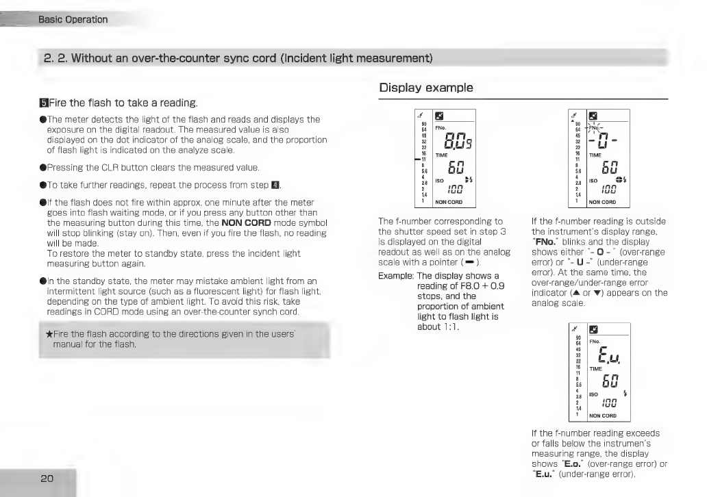
Display
example
4
64
FNo.
5|
mn
2|
ELS
5
|ТІМЕ
&|
Bü
50
БА
28
|!
2
inn
ши
!
|
Non
CORD
Тһе
f-number
corresponding
to
the
shutter
speed
set
in
step
3
is
displayed
on
the
digital
readout
as
well
as
on
the
analog
scale
with
a
pointer
(=).
Example:
The
display
shows
a
reading
of
F8.0
+
0.9
stops,
and
the
proportion
of
ambient
light
to
flash
light
is
about
1:1.
1
|
Non
corp
If
the
f-number
reading
is
outside
the
instrument's
display
range,
"FNo.'
blinks
and
the
display
shows
either
'-
О
-"
(overrange
error)
or
~
U
~"
(under-range
error).
At
the
same
time,
the
over-range/under-range
error
indicator
(А
or
w)
appears
on
the
analog
scale.
&
Н
Емо.
5
Г
2
-
2|
LL
5
|rME
"
8
б
m
56
м
1i
Iso
5
2
100
14
!
|
NON
CORD
If
the
f-number
reading
exceeds
or
falls
below
the
instrumen's
measuring
range,
the
display
shows
“E.o.”
(over-range
error)
or
“Еш.”
(under-range
error).
Table of contents


