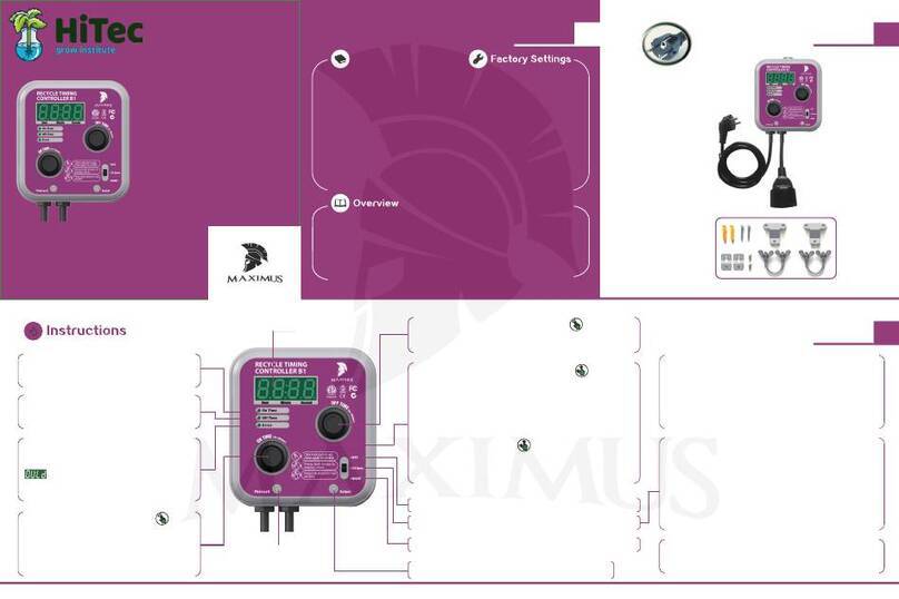
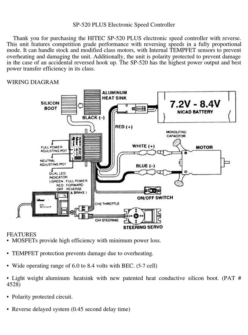
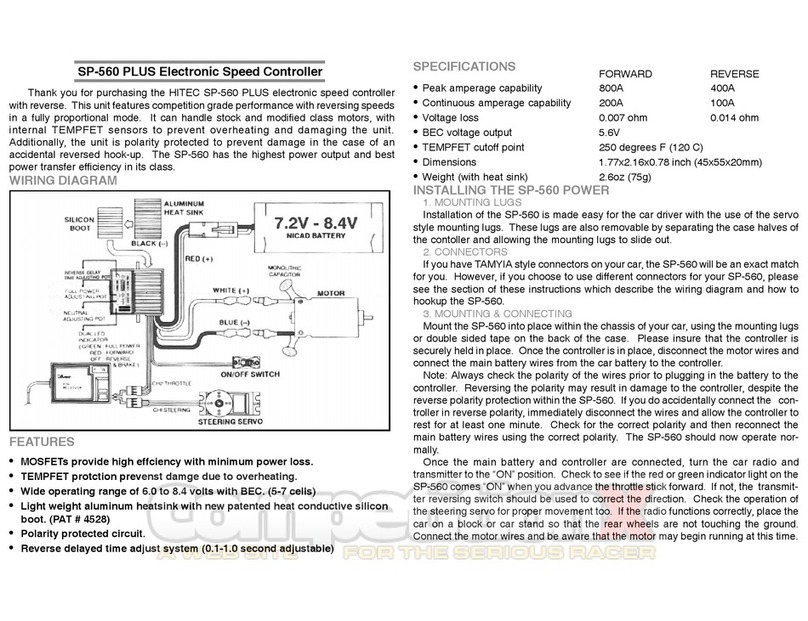
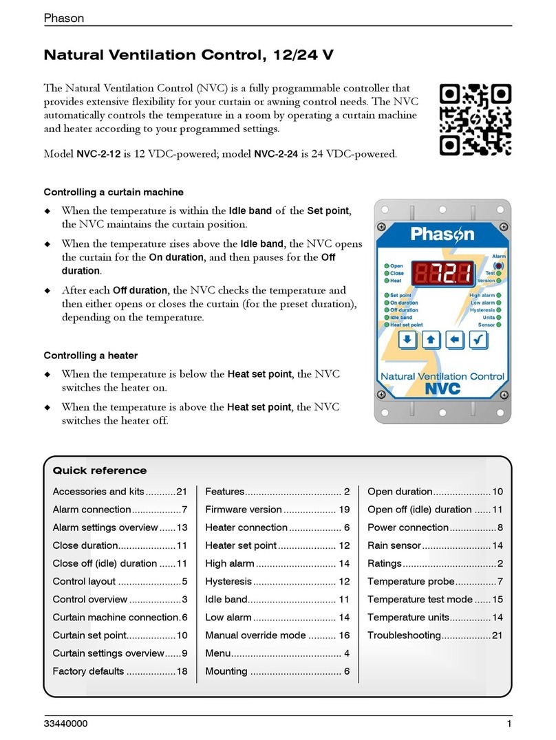
Hi-Tec ALP842 User manual

HITEC
ALP842-Datasheet-R1
1 / 11
HITEC – 61, rue Jean Jaurès – 91160 CHAMPLAN – Tel. : 01 69 74 10 90 – Fax : 01 69 74 10 99
ALP842
Operating Instructions
∆ALP842-24V General view
Contents
1. General characteristics.................................................................................... 1
2. Safety summary............................................................................................... 2
3. Wiring guidelines ............................................................................................. 2
4. Maintenance.................................................................................................... 3
5. Using procedure .............................................................................................. 3
6. Mechanical specifications................................................................................ 4
7. Relay outputs................................................................................................... 4
8. Wiring connections........................................................................................... 5
9. Programming................................................................................................... 6
10. Informations..................................................................................................... 9
1. General characteristics
1.1. Display
4 digits (7 segments) LED RED. Height : 14mm
Messages displayed: When the display exceeds 9999
When the display is less than -1999
During initializing the module (3 secondes)
4 red LEDs for alarm
1.2. Power supply
24 VDC (minimum 20VDC), 5VA
1.3. Setting – Connection
Using the three buttons in front, connection by screw terminals.
1.4. Mémory
Backup all the settings in EEPROM (non-volatile memory).
24 VDC Power
supply
Level Sensor
Pump,…
Alarm…

HITEC
ALP842-Datasheet-R1
2 / 11
HITEC – 61, rue Jean Jaurès – 91160 CHAMPLAN – Tel. : 01 69 74 10 90 – Fax : 01 69 74 10 99
1.5. Sensor input
Current : 0 / 20 mA or 4 / 20 mA – Input impedance 100 Ohm
Voltage : 0 / 10 Vdc
1.6. Accuracy
0,05 % +/- 1 digit
1.7. Relay output
4 relay outputs 5 A at 250Vac or 24Vdc
Alarm Types: Alarm high, low, band, overrange, fault signal
adjustable hysteresis
Alarm display LED programmable
Acknowledging alarms programmable (automatic or maintained)
1.8. Sensor power supply
24 VDC available
1.9. Analog output
Copy of the input signal after linearization : 4 / 20 mA or 0 / 5 V or 0 / 10 V
Refresh period : 100 ms
1.10. Terms of service
Operating : 0 to 50°C Relative humidity max : 85 %
Storage : -20 to 75°C
1.11. Electrical insulation
Between the power supply and other inputs / outputs: 2000 V
Between each relay and other inputs / outputs: 2000 V
1.12. Weight : 300 g
1.13. Conformity
EMC : normes EN50081-1, EN50082-1
2. Safety
Before any intervention, be sure to read this entire manual and strictly follow every
precaution to ensure the protection of persons required to handle this product.
Be careful ! Risk of electric shock.
3. Wiring guidelines
•The power supply must be off before any work on the wiring and for the
duration thereof.
•Wiring must conform strictly to the instructions in this manual and the cable
length should be adjusted to the shortest. Make sure each connection.
•Terminate cables with eyelet lugs suitable for M3.5 screws before connecting
them to the terminals.
•To avoid electromagnetic interference using short cables and flexible enough
appropriate section. Section power cables must be greater or equal to 1 mm2
and isolation greater than 1.5 kV

HITEC
ALP842-Datasheet-R1
3 / 11
HITEC – 61, rue Jean Jaurès – 91160 CHAMPLAN – Tel. : 01 69 74 10 90 – Fax : 01 69 74 10 99
92
46
4. Maintenance
The equipment must be cleaned regularly with a clean, dry cloth (no detergent) to
avoid obstructing its ventilation grids.
5. Installation guidelines
This equipment is intended to be integrated into a electrical housing.
Wiring terminal block on the back of the device must be accessible to the end user.
No electrical conductor must not come into contact with the internal circuitry of the
device to avoid the risk of electrocution for the operator.
A breaker must be installed between the power source and the device to facilitate the
power-on or off.
This circuit breaker or fuse must be installed so as to be easily accessible to the
operator.
The appliance must not be installed in an environment not meeting the conditions
mentioned in this document.
Protection against over-currents: This unit contains no internal fuse. The installation
of an external fuse 1 A / 275 Vac is highly recommended.
The evacuation of the heat generated by the internal circuitry of the apparatus is
effected by the air vents in the electrical housing. These vents must not be blocked.
I / O device must be connected to loads whose magnitudes (voltage, current, ...)
meet the maximum values specified in this document..
5.1. Mounting
The housing is built to DIN panel 96 x 48.
•Prepare the panel with opening according to the dimensions shown below
(mm).
•Remove the brackets and insert the unit into the opening and cut. Reinsert the
brackets then screw them so well plate rubber seal against the panel
Be careful ! Once in position, the unit should not be too close to a
heat source or exposure to vapors or spray liquids.
Electromagnetic precautions: Power cables connected to terminals
must be kept away from any electromagnetic source possible.

HITEC
ALP842-Datasheet-R1
4 / 11
HITEC – 61, rue Jean Jaurès – 91160 CHAMPLAN – Tel. : 01 69 74 10 90 – Fax : 01 69 74 10 99
6. Size (mm)
7. Relay outputs
4 relay outputs have a common point: COM
Each has a point normally open: NO
They support loads 5 A 230Vac or 24Vdc.
Below, here's an example of wiring of 4 loads to the mains.
Side view
Top view

HITEC
ALP842-Datasheet-R1
5 / 11
HITEC – 61, rue Jean Jaurès – 91160 CHAMPLAN – Tel. : 01 69 74 10 90 – Fax : 01 69 74 10 99
charge 1
Neutre
NO1 (12)
NO2 (11)
NO3 (14)
NO4 (15)
Phase
COM (16)
charge 2
charge 3
charge 4
ALP842
∆Wiring 4 charges (230Vac, 5A max) n the 4 relays
8. Wiring connections
1 2 3 4 5 6 7 8 9 10
11 12 13 14 15 16 17 18 N L
NO1
NO2
NO3
NO4
COM
GND
+24V
230VAC
Sensor power
supply
4 relay outputs
mA+
V+ mV+
V-
mA-
+ -
Analog output
PT100
Rear view (terminals)
+
-
Numéro
Description
L et N Phase and neutral (Power supply 230Vac)
2 + Input signal current (mA)
3 + Input signal voltage (V)
4 + Input signal voltage (mV)
5 - Input signal current or voltage
8 + Analog output
9 - Analog output
12 Relay 1 : Point normally open (NO)
13 Relay 2 : Point normally open (NO)
14 Relay 3 : Point normally open (NO)
15 Relay 4 : Point normally open (NO)
16 Relay common (COM)
17 Ground 24VDC power supply for the sensor (GND)
18 + 24VDC power supply for the sensor (+24V)

HITEC
ALP842-Datasheet-R1
6 / 11
HITEC – 61, rue Jean Jaurès – 91160 CHAMPLAN – Tel. : 01 69 74 10 90 – Fax : 01 69 74 10 99
8.1. Connecting a transmitter 4/20mA powered by the 24VDC internal
1 2 3 4 5 6 7 8 9 10
11 12 13 14 15 16 17 18 - +
GND
+24V
24VDC
mA+
mA-
+
-
transmitter
9. Programming
To enter or exit program mode, press together on
+ for 3 seconds.
To view next/previous function on the same level ,
press on or .
To increase the value press together on + .
To decrease the value press together on + .
There are several "levels" of programming, LUL.0 to LUL.7 here are the descriptions.
Level Description
LUL.0 Sensor input programming
LUL.1, LUL.2, LUL.3, LUL.4 Relay outputs programming
LUL.6 Analog output programming
LUL.7 Programming lock
To change from one level to another, press on + or + when LUL
is displayed.

HITEC
ALP842-Datasheet-R1
7 / 11
HITEC – 61, rue Jean Jaurès – 91160 CHAMPLAN – Tel. : 01 69 74 10 90 – Fax : 01 69 74 10 99
9.1. Programming of the level 0 : LUL.0 – Signal input
Parameter Affichages
Description / Range
Current input (0/20 mA or 4/20 mA)
Voltage input (0/10 VDC)
PT100 input
Voltage input -5 mV à 56 mV
Input type
Voltage input from 0 mV to 100 mV
Point position (1, 0.1, 0.01, 0.001)
Resolution
(Filter time constant)
Digital filter time constant : for damping the
too fast variations of the signal. 1 to 99
seconds (or OFF). If you notice the "noise" in
the signal, increase this value.
(Display update rate) Display update rate (0.5 to 6.0 sec).
Zero offset from -200 to +200). (To re-adjust
the measurement for example)
Number of scaling points for linearization.
For a simple straight line, leave 2
Display value scaling point 0 (low).
(mA) Input value scaling point 0 (low).
Display value scaling point 1 (high)
(mA) Input value scaling point 1 (high)
Note : For SCLP > 2, the other points are (DSC2,ISC2), (DSC3,ISC3),…
No reverse
Reverse scaling Reverse scaling
Set point high limit
Set point low limit
Number of programs
No reset
(RESET) All parameters set to factory setting
9.2. Programming of level 1 : LUL.1 – Relay output 1 (idem for LUL.2, 3, 4)
Parameter Display Description
Program number
Alarm high limit (mode HA or BAND).
Alarm low limit (en mode LA or BAND).
Alarm hysteresis
RUN P

HITEC
ALP842-Datasheet-R1
8 / 11
HITEC – 61, rue Jean Jaurès – 91160 CHAMPLAN – Tel. : 01 69 74 10 90 – Fax : 01 69 74 10 99
Delay timer before switching (from 0 to 99.59
min.sec).
Alarm off
High alarm
Low alarm
Band alarm : snaps if the signal is above HA
or below LA
Fault diagnosis alarm
Alarm mode
AFail output alarm
The alarm clears when the cause
is no longer
present.
Latch Alarm
Alarm status will be preserved at any process
condition
Alarm activates when the system boots
Hold Alarm The alarm is inhibited in the initialization
phase to prevent it activates if the signal
has
not yet reached its steady value.
(The most common case)
No alarm relay inactive (NO)
Alarme relay active
Relay status No alarm relay active (NF)*
Alarme relay inactive
* Attention !!! In case of power failure, the
relay is anyway open (NO).
No annunciator.
Red LED blinking (0.2 seconde).
Alarm annunciator LED blinking + display alarm
9.3. Programming of level 6 : LUL.6 – Analog output
Parameter Display Description / Range
The copied signal is proportional
to the input
signal.
manual mode Manual mode. The output signal is constant
determined by the parameter PTAG (see
below).
Low scaling point
High scaling point
In case of sensor failure the output can be s
et
to high value of range
Sensor error level
In case of sensor failure the output can be set
to low value of range
Percentage of 0.00 to 100.0% of the desired
value of the analog output

HITEC
ALP842-Datasheet-R1
9 / 11
HITEC – 61, rue Jean Jaurès – 91160 CHAMPLAN – Tel. : 01 69 74 10 90 – Fax : 01 69 74 10 99
9.4. Programming of level 7 : LUL.7 – Locked system
Parameter Display Description / Range
User identification (0000 à 9999).
Unlimited access to parameters of level 0
Read access level 0
(LK-0) No access to parameters of level 0
LK-1, LK-2, LK-3, LK-4, LK-5 : Same parameters
Unlilited to parameters of level 6
Read access level 6.
(LK-6) No access to parameters of level 6
N : Do not change
(nouveau mot de passe)
Y : Change the password
New password (0000 à 9999).
10. More information
10.1. Option to display alarms
Press on to view the status of alarms.
Press on + to see the next alarm.
(Only active alarms are displayed)
Press on + to acquit the displayed alarm. (Case « Latch : ON »)
Example of display for alarm 1 :
: Low Alarm
: High Alarm
: Input signal failure (Fail Output)
: Alarm system failure (Fail Diagnosis)

HITEC
ALP842-Datasheet-R1
10 / 11
HITEC – 61, rue Jean Jaurès – 91160 CHAMPLAN – Tel. : 01 69 74 10 90 – Fax : 01 69 74 10 99
Input
(mA)
Display
(digits)
ISC0
4.00
ISC1
20.00
DSC1 : 1000
DSC0 : 0
RSCL = NO
(No reversal)
10.2. Linearization (Scale setting)
10.2.1 Common case : rectangular tank 2 points
The diagram below gives an example of setting for a display level 0 to 1000 for an
input signal from 4.00 to 20.00 mA.
SCLP
= 2
Point 0 :
ISC0
= 04.00 ;
DSC0
= 0
Point 1 :
ISC1
= 20.00 ;
DSC1
= 1000
With ISC1 = 20, DSC1 corresponds to the full scale of the sensor.
∆
Usual scaling : 2 p ints right lane
It's possible to invert the way of linearization in choosing
RSCL = YES. In this case, the display will be 1000 for 4.00 mA and 0
for 20.00 mA.
To display the
volume
of the tank (V), if the heigh (H) is different from the full scale
of the sensor (PE), enter the following points :
SCLP
= 2
Point 0 :
ISC0
= 04.00 ;
DSC0
= 0
Point 1 :
ISC1
= 20.00 ;
DSC1
= (PE x V) / H

HITEC
ALP842-Datasheet-R1
11 / 11
HITEC – 61, rue Jean Jaurès – 91160 CHAMPLAN – Tel. : 01 69 74 10 90 – Fax : 01 69 74 10 99
10.2.2 Case for cylindrical tank : 10 points
In this case, it should enter the number of points desired in SCLP, then enter them in
order.
The diagram below shows an example of a 5-point linearization (0 to 4).
In this case, the parameters are:
SCLP = 5
Point 0 : ISC0 = 04.00 ; DSC0 = 0
Point 1 : ISC1 = 06.00 ; DSC1 = 1500
Point 2 : ISC2 = 12.00 ; DSC2 = 5000
Point 3 : ISC3 = 14.00 ; DSC3 = 8500
Point 4 : ISC4 = 20.00 ; DSC4 = 9999
The system will ensure that the curve is increasing. That is to say, if
we look for example DSC2 up above 8500 (DSC3 value), then DSC3
will also be increased in order to stay on DSC2 least.
Input
(mA)
Display
(digits)
ISC0
4.00
ISC1
6.00
ISC2
12.00
ISC3
14.00
ISC4
20.00
DSC4 : 9999
DSC3 : 8500
DSC2 : 5000
DSC1 : 1500
DSC0 : 0
∆Linearizati n at several p ints
You will find assistance in calculating linearization at the web address :
www.hitec.fr/line
(Calculation of the volume from a chart height / volume, or a cylindrical tank).
This manual suits for next models
1
Table of contents
Other Hi-Tec Controllers manuals
Popular Controllers manuals by other brands
Skope
Skope SCS Connect Technician manual

National Instruments
National Instruments sbRIO-9605 Operating instructions and specifications
Bosch
Bosch CL550 Configuration and Commissioning Software Manual
AUMA
AUMA PROFOX PF-Q80 manual

DT Research
DT Research DT136 Basic operation guide
SICK
SICK RMS1000 quick start
Panasonic
Panasonic EYFRZ01 operating instructions
Lutron Electronics
Lutron Electronics seeTouch installation instructions
SMC Networks
SMC Networks LECP6 Series Supplementary Operation Manual
YASKAWA
YASKAWA JEPMC-MP2300-Y Series user manual
KMC Controls
KMC Controls CSC-1001 installation guide
Carel
Carel FCR3 user manual
