Hi-Tec Aurora 9 User manual

22 23
9 CHANNEL 2.4GHz AIRCRAFT COMPUTER RADIO SYSTEM 9 CHANNEL 2.4GHz AIRCRAFT COMPUTER RADIO SYSTEM
There are a several accessories available for your Aurora transmitter. Check the Hitec web site for information as more
accessories are added to the Aurora and Hitec 2.4GHz system product lines.
Modules
SPECTRA 2.4 Hitec AFHSS 2.4GHz System Part # 28315
SPECTRA PRO 72MHz Synthesizer Part # 23772
Transmitter Battery Pack
6 cell, 1300mA NiMH Pack Part # 54128
HPP-22 PC Interface
Used to interface the Aurora with a PC, it will offer a variety of functions including updating the Aurora with future
software versions, Part # 44470
Neckstrap
Many pilots prefer to use a neckstrap when flying. Hitec offers our comfortable strap and swivel snap neckstrap for the Aurora,
Part # 58311
Trainer Cord
The Hitec trainer cord, system can be used to link two Hitec transmitters together for flight training purposes.
Part number # 58321 includes the complete trainer cord assembly.
Gyros
We recommend the Hitec HG-5000 gyro but the Aurora was created to use almost any popular gyro available on the market.
Standard Economy Gyro Pack (HG-5000 Gyro, HSG-5083MG Gyro Servo, Three HS-65HB) Stock # 40105
Standard Metal Gear Pack (HG-5000 Gyro, HSG-5083MG Gyro Servo, Three HS-65MG) Stock # 40103
Pro Heli Pack (HG-5000 Gyro, HSG-5083MG Gyro Servo, Three HS-5065MG) Stock # 40101
Battery Charger
To charge the supplied NiMH transmitter battery.
Use the CG-S45 battery charger. Part # 44450 (for 110V)
Use the CG-S35 battery charger. Part # 44350 (for 220V )
Servo Installation Wiring
Hitec offers a variety of light and heavy duty servo installation wiring. “Y” harnesses, extensions, small and large switch harnesses
are all available from your hobby dealer.
Receivers
Hitec 2.4GHz System
When using the SPECTRA 2.4GHz System Module, any Hitec Optima series receiver can be used.
Optima 6 Part # 28410 Optima 7 Part # 28414 Optima 9 Part # 28425
72MHz FM PPM and Hitec QPCM Receivers.
The SPECTRA PRO frequency module allows the use of all positive or negative shift 72MHz band receivers.
The Hitec QPCM receiver format is also supported in the Aurora, part # 191721.
Servos
Any brand of modern servo with a 1.5 ms neutral position can be used with the Aurora. This includes any prior, or current
Hitec manufactured servo.
Aurora Transmitter Accessories Aurora Transmitter Controls
It is strongly recommended to use Hitec “S” Heavy Duty High Channel Switch Harness with
Receiver Charger Cord (Stock # 54407S) for Optima series Receivers.
Warning
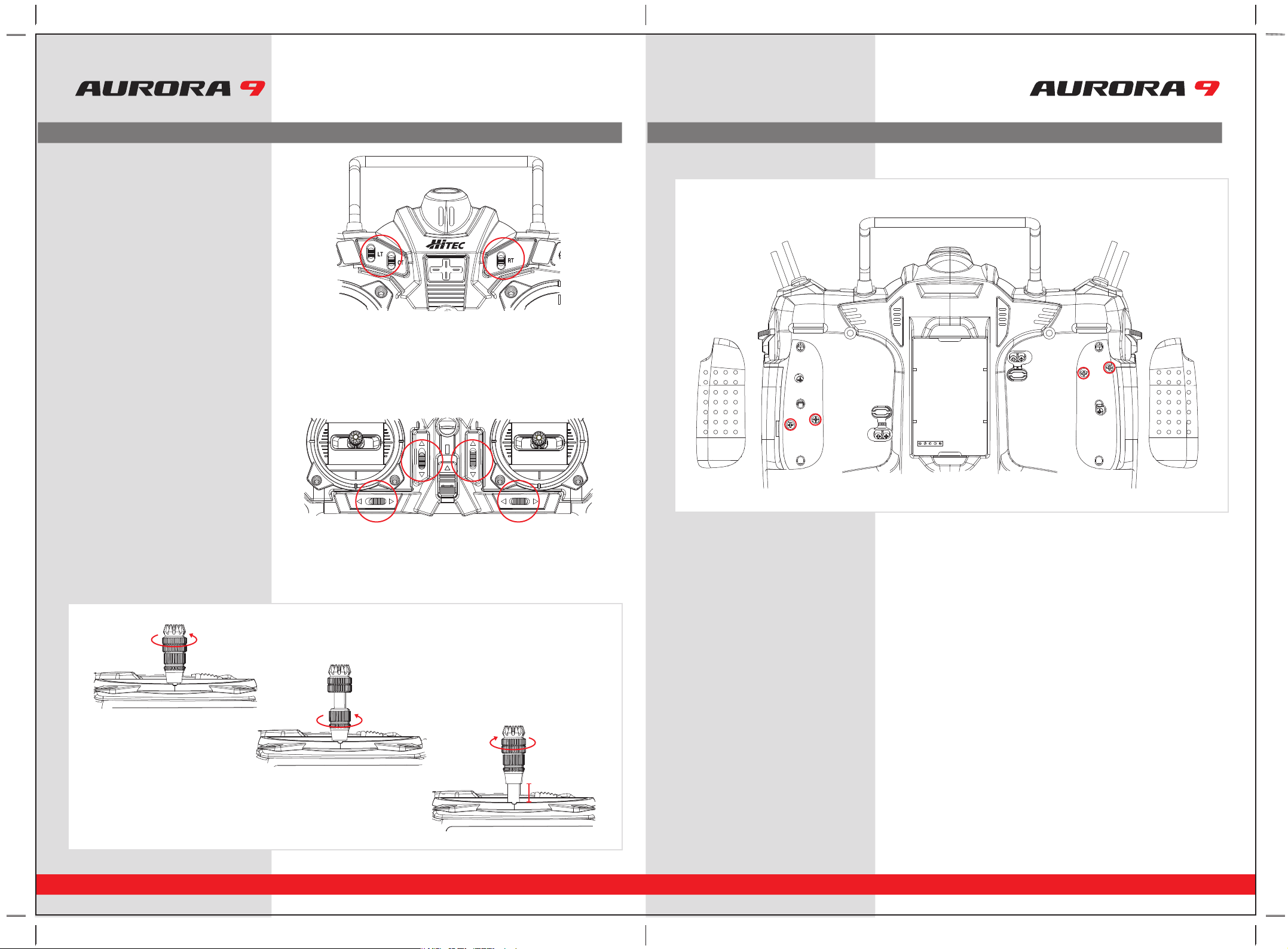
Slider Volumes
Side sliders are used as variable controls on several of the functions by default but can be changed if you wish. Like all of the Aurora
controls, you can choose an almost infinite number of control layouts.
1. A, B C, D, E, F, G, H, switchs
2. J1, J2, J3, J4 gimbles
3. Neckstrap hook
4. LS and RS sliders
5. All Digital trims, T1, T2, T3 and T4
6. On-Off switch
1
3
6
4
2 2
5
5 5
5
4
1
24 25
9 CHANNEL 2.4GHz AIRCRAFT COMPUTER RADIO SYSTEM 9 CHANNEL 2.4GHz AIRCRAFT COMPUTER RADIO SYSTEM
Aurora Transmitter Controls Aurora Transmitter Controls
LT, CT, RT Switches
These switches can be used as a channel control and
are used as adjustment controls for fine tuning many
of the Aurora features.
Digital Trims
The Aurora features digital trims on the face of the transmitter for throttle and the three main control functions of pitch, roll and yaw.
• A gentle pull to one side of the switch will cause the control surface to move one trim step and the radio to “beep” once.
• Hold the switch over to one side to rapidly trim a control surface.
• The size of the trim step can be adjusted in the System – TrimStep function menu.
• The graph on the screen will indicate how much movement is applied to the control surface by the trim function.
• Last trim position will be saved in memory should you switch to another model.
Stick Length Adjustment
Hands come in all sizes so to accommodate everyone we use a two piece stick “top” that can be adjusted to fit a wide variety of users.
Stick Tension Adjustment
Control Mode Changes
The Aurora offers unlimited options when customizing the gimble control functions for Mode 1, 2, 3 and 4 users. In addition the Aurora also
features two manual mode set-up menus. These are all located in the System – Mode function menu. Refer to page 63 for a detailed
explanation on how to select the mode you wish to fly.
• Easy ratchet adjustment for the throttle on each gimble.
• The radio is factory set-up for Mode 2 users in America.
• Remove the rubber pads by gently pulling up a corner and slowly pulling them off.
• Use a small Phillips head screwdriver to turn the adjustment screw clockwise to increase the spring tension, and counterclockwise to
decrease the tension of the spring.
• Fit the rubber grip pads back into place when finished.
• Separate the top from the bottom piece and adjust the top piece to the length required.
• Screw the bottom up against the top piece to “jam” lock everything into position.
M1/3
J1 J2
J3
J4
M2/4
26 27
9 CHANNEL 2.4GHz AIRCRAFT COMPUTER RADIO SYSTEM 9 CHANNEL 2.4GHz AIRCRAFT COMPUTER RADIO SYSTEM
Aurora Transmitter Controls The First Screen
First Screen Additional Menu
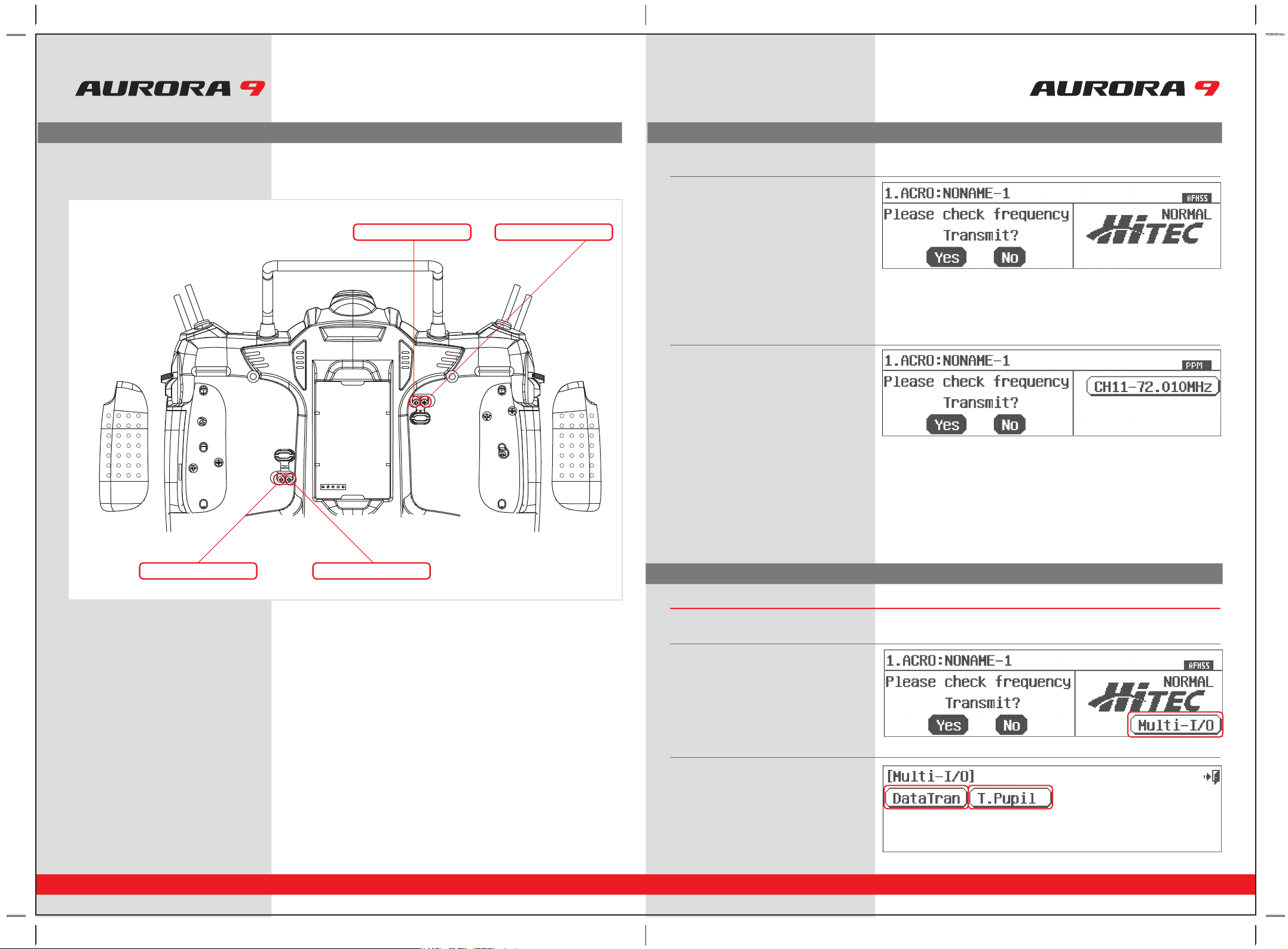
When you first turn on the Aurora, depending on if the radio is in 2.4GHz or the 72MHz format, the following screen will appear.
In 2.4GHz mode;
In 72MHz mode;
To access the Multi-I/O port screen;
a. Plug in the trainer cord or
HPP-22 PC interface in the “trainer” port.
b. Turn on the Aurora.
d. Press DataTran icon for transfer data between
radios or save/load data from /to a PC.
e. Press T. Pupil icon to set the AURORA as
student mode.
Note : In the pupil mode some functions
will be restricted.
c. Press the Multi-I/O port icon to access the menu.
1. The upper line has the number and name of
the active model on the left.
2. The AFFHS 2.4GHz bandwidth you are using
appears in the upper right corner,
with the signal type below it, either NORMAL
or ScanMode.
3. You are prompted to “Please check frequency”
and asked to “Transmit” by selecting the Yes or
No icon.
1. The upper line has the number and name of
the active model on the left.
2. The bandwidth type you are using appears in
the upper right corner, with the signal type
below it, either PPM or QPCM.
3. The channel of the active model is displayed
on the right. Press the frequency number icon
to enter the Frequency menu. See page 57, for
detailed instructions on changing the frequency.
4. You are prompted to “Please check frequency”
and asked to “Transmit” by selecting the Yes or
No icon.
The Multi-I/O port
There is one more feature of the first screen to share with you, the Aurora displays a Multi-I/O format that is accessed in the
first screen of both the 2.4 and 72MHz format.
Stick Ratchet Adjustment
Throttle ratchet tension can also be adjusted to accommodate different flying styles. Some users prefer a very stiff, positive detent in the
throttle stick; while heli users often use a very light, sometimes smooth throttle/collective stick “feel”.
• Peel up the correct rubber dust cover over the throttle stick tension adjustment screws for the mode you are flying.
The radio is factory set-up for the popular mode 2 control format.
• There are two adjustment screws. Note in the diagram which one you want to adjust.
• Use a small Phillips head screwdriver to turn the adjustment screw clockwise to increase the ratchet tension, and counterclockwise to
decrease the tension of the ratchet.
• To switch from airplane to heli, or heli to airplane, turn the appropriate screw counterclockwise until the stick movement is smooth,
then turn the other screw clockwise to apply ratchet pressure and adjust as necessary.
M1/3
J1 J2
J3
J4
M2/4
Heli tension adjustment screw Acro tension adjustment screw
Heli tension adjustment screwAcro tension adjustment screw

28 29
9 CHANNEL 2.4GHz AIRCRAFT COMPUTER RADIO SYSTEM 9 CHANNEL 2.4GHz AIRCRAFT COMPUTER RADIO SYSTEM
Home Screen Menu Home Screen Menu
2. Model Name
• Displays the current models name.
• Press to select the model choice menu.
3. Flight Condition
• Displays the current flight condition for the active model.
• Press to access the flight condition menu.
4. Aircraft Type Icon
• Will be either ACRO, GLID or HELI depending on active model type selected.
• Press to access the Model function menu.
5. Custom Folder
• Contains model functions copied over to the Custom folder for the active model.
• Press to select the Custom menu.
6. System Menu
• Press to access the System functions menu for the active model.
7. Channel Number
• Appears when the Aurora is used with the SPECTRA PRO module and PPM or QPCM is the selected modulation format.
• Shows the transmit frequency channel number for the active model.
• Press to access the channel choice menu.
8. Digital Trim Position Indicators
• Shows the position of the digital trims on the throttle and three main flight controls, roll, pitch and yaw.
• Press to access the sub trim menu.
9. Power Bar Indicator
• Press to select between % of power left or voltage displays.
10. Signal Modulation
• Will show the signal type selected for the active model, PPM, QPCM or AFHSS.
11. Active or Inactive Transmit Icon
• Displays the transmitters transmit status.
• If the icon is dark, the Aurora is not transmitting.
• If the icon is clear with lighting bolts and the “on air” text, the Aurora is transmitting.
12. INTEG-T Timer
• Displays the “total time on” for your Aurora transmitter. Can be reset in the Timer menu. Timer 1 and Timer 2
• Press to access the timer 1 and 2 menus.
The 2.4GHz operation home screen is a little different, with the following information;
13. Receiver Battery Power Indicator
• Displays receiver’s bettery level
* Available for Hitec AFHSS 2.4GHz system only.
DataTran
Select Data Tran to transfer model set up data
between two AURORA’s, or to save or load data
to a PC.
Radio A Radio B
T.Pupil
Selecting T.Pupil forwards the radio into the
home screen in the training mode.
This is used to place an Aurora in the
student format.
This function is not used when the Aurora is to be
used in the master format.
For more information on how to use the
Aurora training system mode, see page 60.
Home Screen Menu
Many of the common functions can be selected for manipulation from the Aurora home screen by pressing their icon. Here are the
definitions of the Home screens icons. Please note that most of these functions are explained in greater detail within this manual.
1. Model Number
• Displays the current model memory slot number, 1 though 30.
• Press to select the model choice menu.
13 7 10 9
12
11
865
2
4

30 31
To help you get the maximum benefit from your Aurora, we will guide you through a simple set-up of a standard sport plane.
The operations shown during this exercise will help you learn many of the basic programming steps required by most of the Auroras features.
9 CHANNEL 2.4GHz AIRCRAFT COMPUTER RADIO SYSTEM 9 CHANNEL 2.4GHz AIRCRAFT COMPUTER RADIO SYSTEM
Receiver channel assignments are;
Simple Powered Plane with one or two aileron servos.
#1 Aileron
#2 Elevator
#3 Throttle
#4 Rudder
#5 Second Aileron (if used)
Simple two channel un-powered glider.
#1 Aileron (plug your rudder or aileron servo in ch. 1)
#2 Elevator
After installing the servos and accessories in your aircraft, follow these steps to set-up your first airplane.
For safety reasons during this set-up exercise on an electric powered plane,
remove the propeller.
Warning
2. The first screen is the transmit option,
select No.
1. Turn on the transmitter;
do not turn on the airplane.
3. This is the home screen;
select the wrench icon for the System menu.
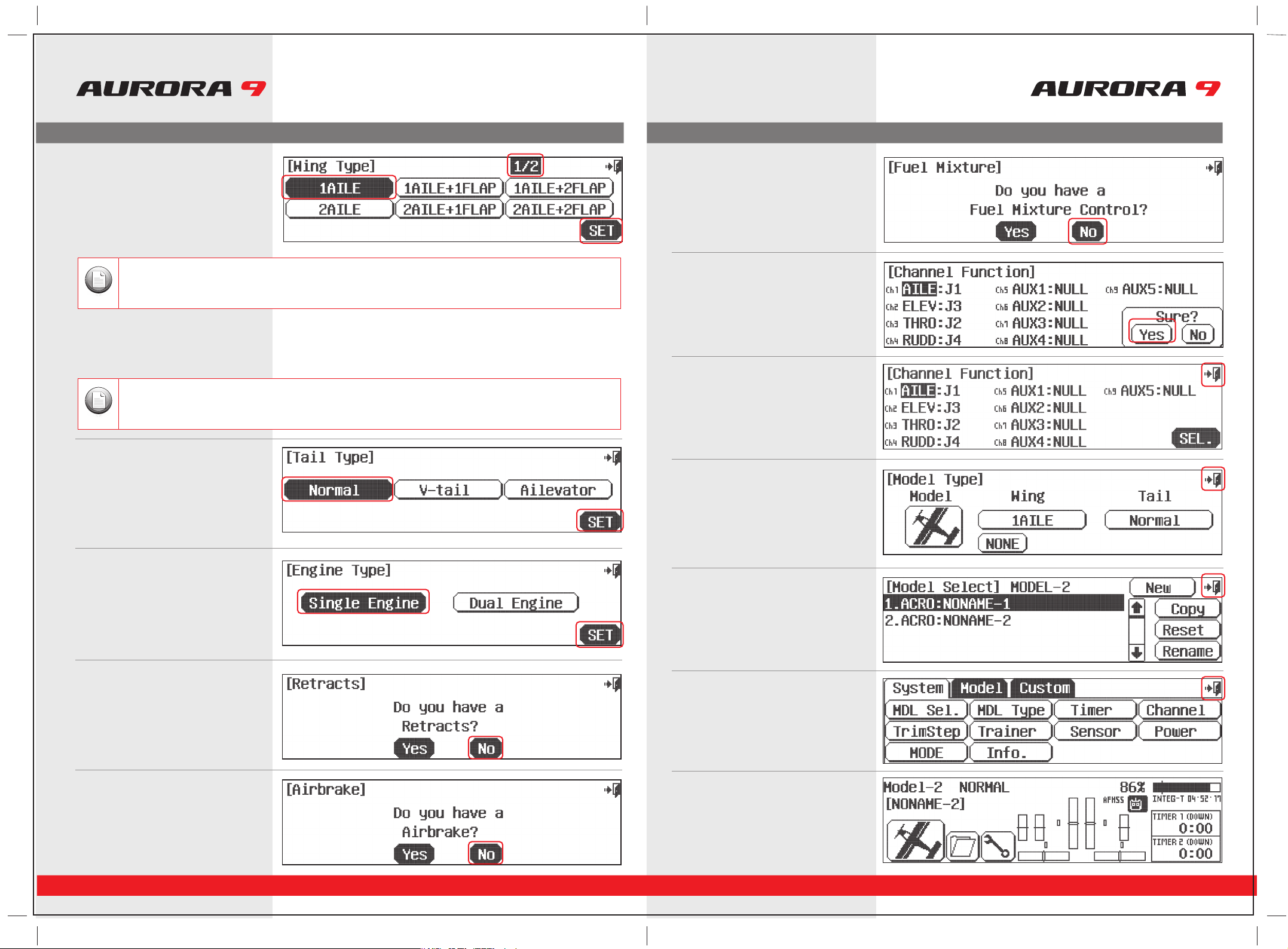
4. Note the system menu function choices,
select, MDL Sel .
6. Select, Yes to confirm the selection of
a new model.
7. At the Model naming menu,
name your new model using the keyboard.
a. Press Shift to see the other characters.
b. When done press, Enter.
8. Here at transmit option screen, press, No.
We do not wish to transmit yet.
9.
Next you are drawn into the model type screen
where we select ACRO (the airplane icon on
the left).
10. Select change to ACRO, Yes at the model
type change confirmation screen.
If you are setting-up a powered or un-powered glider, we will be programming your plane into the ACRO menu for
our demonstration. Later you can explore the functions found in the GLID menus.
Note
Note
We are programming a new model into the model memory slot number two, not the model memory slot one.
For the purpose of this exercise it will ensure a fresh model memory with no existing programming.
5. At the model selection screen press, New.
System Menu Programming
System Menu Programming
Quick Start Guide to Set up a Simple Powered Airplane or Glider
Section Two
System Menu Programming
32 33
9 CHANNEL 2.4GHz AIRCRAFT COMPUTER RADIO SYSTEM 9 CHANNEL 2.4GHz AIRCRAFT COMPUTER RADIO SYSTEM
14. Retracts? Press No.
15. Airbrakes? Press No.
16. Fuel Control? Press No.
17. Ok here are the channel assignments the
radio has selected for you.
They should be appropriate. Select Yes.
18. These are the control functions the radio has
selected for you. They should be fine.
Select the back (Exit) icon at the
screens upper right.
19. This is the model type screen showing the
functions we selected. Select the back
(Exit) icon at the screens upper right.
20. We are now back to the model select screen.
Back out of it with the Exit icon at the
screens upper right.
21. Back to the system menu page,
and one more time, press the Exit icon.
22. Here at the home page take little break,
turn off the transmitter and prepare your
model to be set-up.
a. For our sample plane, you must select how many servos your wing has and what
they control.Select 1AILE if you have one aileron servo controlling both ailerons.
OR 2AILE if your plane has 2 aileron servos in the wing.
b. Then press the SET icon.
11. Here is the screen that will tell the transmitter
what kind of wing your plane has.
12. Next select your planes tail type.
a. Select Normal .
b. Again press SET.
There is a
1/2
icon in the upper right of the screen. This means there are two pages in this menu. Touch the
1/2
icon and
note the second screen has even more wing type selections. Many function menus will have more than one screen of
options. Check for the
1/2
, or fraction icon as you program your plane into the radio.
Note
Depending on what you select in this, and for the following menu choices, the radio will automatically optimize the
functions for your choices. In other words, if you select a wing type without flaps, there will be no flap function control
options in that model memories programming.
Note
a. Select, Single Engine.
b. Press SET.
13. At the engine type screen,
System Menu Programming

Model Menu Programming Model Menu Programming
9 CHANNEL 2.4GHz AIRCRAFT COMPUTER RADIO SYSTEM 9 CHANNEL 2.4GHz AIRCRAFT COMPUTER RADIO SYSTEM
34 35
Ok, are you ready? You have your model all prepared and ready to program? Let’s go!
23. Turn on the transmitter,
select Yes to transmit.
24. At the home page, let’s select some model
functions by pressing the plane icon
at the lower left of the screen.
28. Select EPA from the model menu
a. Move the aileron control stick all the way to the left.
The R 100% should be highlighted.
b. Using the + LST – icon set an appropriate value, more than 100% to increase the
travel, or less than 100% to decrease the servo arm travel.
c. Now move the aileron stick all the way to the right and set the travel value for
the right side.
d. Press the 100% value icon for any other channel you wish to set an EPA value for
and follow steps a-c.
e. When done, back up to the model menu by selecting the Exit icon.
EPA stands for “end point adjustment”. With the EPA function you can set the servo arm travel distance by lengthening or limiting how
far the arm moves. This function can help avoid binding or damaging the aircraft control surfaces, if set-up properly.
In our example we will adjust the channel 1 aileron servo.
c. Follow this procedure for any channels requiring sub-trim.
d. When done, back up to the Model menu by selecting the Exit icon.
Sub trim is not the place to do a major adjustment. Any servo needing more than 40 points of movement should be
adjusted by moving the control horn or adjusting the linkage.
Caution
Using the fol
lowing functions are not mandatory. For the purpose of our quick set-up guide tutorial they will explain most of
the fundamental programming techniques available in the Aurora. We highly suggest you follow along with programming
the EPA, dual and exponential rate functions. Doing so will teach you valuable lessons and the basics you need to get the
most out of your Aurora.
Note
25. The model menu is one of those “two page”
screens, note the 1/2 icon. Here are all the
functions the Aurora can apply to our rather
simple selected model.
26. Select Reverse from the model menu
Now turn on power to your model. Within a moment, you should have control over your model with the transmitter.
a. Move your controls, are all the servos going in the correct direction?
If not, select the channel to reverse, then press the REV icon.
b. Press Yes when asked “Sure?”
c. Do this until all servo throw directions are correct.
d. Back up to the model menu by selecting the Exit icon.
27. Select Sub-Trim from the model menu
Your servo control arms should be as close to 90 degrees as possible, and the control surfaces as close to level as you can make them
by adjusting the control linkages. Sometimes small adjustment must be made to “center” the control surface using the sub-trim function.
a. Select the control/channel to adjust by pressing its icon.
b. Using the + RST – icon at the screens lower left corner, adjust a value as necessary
by selecting the plus or minus icon. Select RST to bring the value back to zero if
you wish. You should see the control surface moving as changes are made with
the + or – icon.
Throttle Lock
The Aurora features a "throttle lock" function that can be activated when the transmitter is transmitting a signal.
We encourage you to apply the throttle lock as a safety precaution against "accidental throttle application".
TipTipTip
Tip
a. Turn the throttle lock on and off from the home page by pressing the Model icon for two seconds.
Throttle lock is confirmed when the “THRO Lock” icon is displayed.
Model Menu Programming
3736
9 CHANNEL 2.4GHz AIRCRAFT COMPUTER RADIO SYSTEM 9 CHANNEL 2.4GHz AIRCRAFT COMPUTER RADIO SYSTEM
When flying very fast, small tiny movements of the control surface are required. We will call the small movements “low rates”.
Since we already have our high rates set-up, let’s set another rate, or servo arm travel distance that is smaller and will give us small
control surface movement. This “low rate” can be activated by selecting a switch when you are flying.
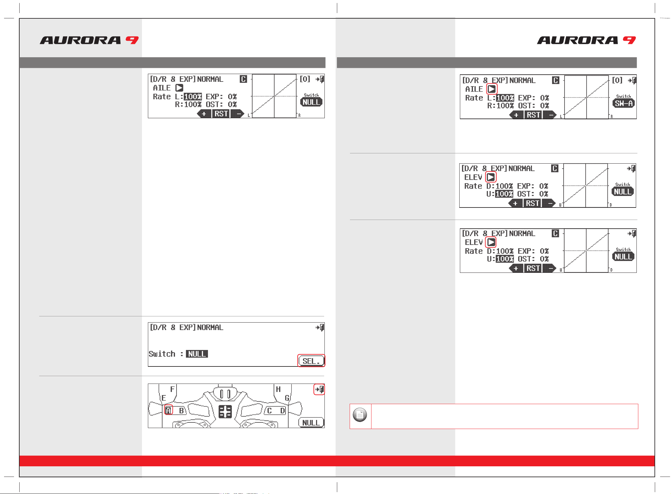
Here is how to set up your aileron and elevator travel using the dual rate functions.
a. The first control surface to change is the aileron;
AILE pops up as the active function when entering this screen.
b. Select “Rate” to highlight both R&L. This allows you to change both sides of the
servos travel rate at the same time.
c. Move the aileron stick to the left, hold it there and press the – icon until
you reach 75%.
d. Now select a switch that we can throw while flying that will cut the aileron
travel down to our 75% setting.
e. Press the NULL icon to select the switch for our dual rate function.
This screen holds two valuable functions, dual rates and exponetial rates. Both functions are controlled at this screen.
Using the dual rate function allows you to select a switch that can change the travel rates or distance the servo arm moves a control surface
.
We will first demonstrate dual rates, then show you how to program exponential rates.
A good example is that; even a very fast plane must take off and land at a relatively slow speed compared to how fast it may fly at full
throttle. What is needed are two servo arm travel rates, dual rates, that we can program and then use a switch to select between these
rates. When flying slow, full control movement is necessary, we will call this “high rates”, and it is what you currently have set-up based
on the EPA values.
29. Select D/R&EXP from the model menu
a. Let’s select switch “A”.
b. Select the Exit door icon twice to back out.
31. This is a map of the Aurora switch layout.
You can put the aileron dual rate function
on any of the switches shown.
30. At the intermediary switch screen
press the SEL icon.
Now we can apply exponential rates to the aileron and elevator controls.
Using exponential rates allows you to shape the normally linier movement of a control surface. Our goal is to soften the middle of the
stick around the center point for the "high rates". You will see this curve shaped on the graph displayed on the screen. Using negative
expo values will help any pilot fly smoother on high rates, with greater control over their aircraft.
We will apply a -40% value to the expo setting for both the aileron and elevator high rates.
a. Apply expo to your aileron control by selecting the AILE controls using the control
select arrow.
b. With the switch “A” in the position that gives us our high rate setting of 100% travel
in dual rates, touch the EXP 0% icon to activate it.
c. Now press – to apply a -40% value. See how the curve of the aileron servos
movement changes to “soften” the center of the aileron control sticks travel.
d. Change to the elevator again by pressing the arrow to the right of the AILE.
e. Repeat steps to program our -40% EXPO value for the elevator high rates.
Your plane should now be ready to fly. Do a range check and pre-flight, then go have fun!
Now by throwing one switch, you can select to use dual rates and have expo on your elevator and ailerons.
34. Using Exponential Rates
For more advanced users, different expo and D/R values can be applied with individual switches and/or
under multiple flight conditions.
33. Follow steps 29 -31 to program a 75%
value for the elevator dual rate. Select the
elevator dual rate to be active by assigning
it on the same switch, “A” for the purpose
of our demonstration. Be sure to put the
75% elevator value on the same switch
“position” as our 75% aileron value.
8
a. Run through the same steps to select a dual rate for your elevator.
We change to the elevator function by pressing the arrow icon to the right of AILE.
Now it should read ELEV.
32. Now we are back to the D/R&EXP screen.
Note
Model Menu Programming

System Menu Programming
To help you get the maximum benefit from your Aurora, we will guide you through a simple set-up of a common collective pitch
120CCPM heli. The operations shown during this exercise will help you learn many of the basic programming steps required by most of
the Auroras features.
Channel assignments are;
#1 Aileron or “roll” cyclic
#2 Elevator or “pitch” cyclic
#3 Throttle
#4 Rudder or tail rotor pitch
#5 Gyro function
#6 Pitch Collective
After installing the servos and accessories in your heli, follow these steps to set-up it up.
9 CHANNEL 2.4GHz AIRCRAFT COMPUTER RADIO SYSTEM 9 CHANNEL 2.4GHz AIRCRAFT COMPUTER RADIO SYSTEM
38 39
1. Turn on the transmitter; do not turn on the Heli.
2. The first screen is the transmit option,
select No.
5. At the model selection screen press, New.
6. Select, Yes to confirm the selection of
a new model.
7. At the model naming menu,
name your new model using the keyboard,
8. Here at transmit option screen,
press, No. We do not wish to transmit yet.
a. Press Shift to see the other characters.
b. When done press, Enter.
10. Select change to HELI, Yes at the model type
change confirmation screen.
11. Here is the screen that will tell the transmitter
what kind of swash type your heli uses.
9. Next you are drawn into the model type
screen where we select HELI
(the heli icon on the right).
3. This is the home screen;
select the wrench icon for the System menu.
4. Note the System menu function choices,
select, MDL Sel .
For safety reasons during this set-up exercise on an electric powered heli please remove the blades and/or un-plug the
motor from the speed control.
Warning
We are programming a new model into the #2 model memory slot, not the model memory one slot. For the purpose of
this exercise it will ensure a fresh model memory with no existing programming.
Note
System Menu Programming
Quick Start Guide to setting up a Simple Heli
Section Three
9 CHANNEL 2.4GHz AIRCRAFT COMPUTER RADIO SYSTEM 9 CHANNEL 2.4GHz AIRCRAFT COMPUTER RADIO SYSTEM
40 41
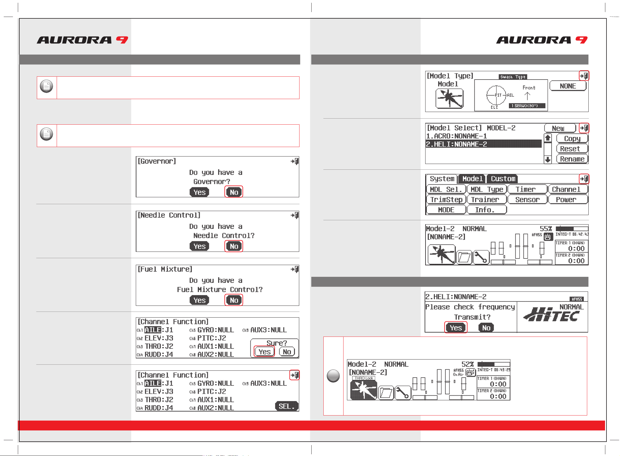
a. For our sample heli, you must select what swash type your heli uses. Most will
select 120 or 90 degree CCPM swash type. Consult your heli manual to find out
what swash type your heli uses. Then press the SET icon.
12. Governor? Press No.
13. Needle control? Press No.
19. Back to the system menu page and
one more time, press the Exit icon.
20. Here at the home page take little break,
turn off the transmitter and prepare your
model to be set-up.
14. Mixture Control? Press No .
15. Ok here are the channel assignments,
the radio has selected for you.
They should be appropriate, select Yes.
16. This screen lets you change the control
function, for now, select the back (Exit)
icon at the screens upper right corner.
There is a1/2 icon in the upper right of the screen. This means there are two pages in this menu. Touch the1/2 icon
and note the second screen has even more swash type selections. Many function menus will have more than one
screen of options. Check for the 1/2 icon as you program your heli into the radio.
Note
Depending on what you select in this, and for the following choices of this menu, the radio will automatically
optimize the functions for your choices.
Note
17. This is the model type screen showing the
functions you selected.
back out fo it with the Exit icon
18. We are now back to the model select screen,
back out of it with the Exit icon.
21. Now turn on the transmitter,
select Yes to transmit.
Throttle Lock
TThe Aurora features a "throttle lock" function that can be activated when the transmitter is transmitting a signal.
We encourage you to apply the throttle lock as a safety precaution against "accidental throttle application".
TipTipTip
Tip
a. Turn the throttle lock on and off from the home page by pressing the Model icon for two seconds.
Throttle lock is confirmed when the “THRO Lock” icon is displayed.
System Menu ProgrammingSystem Menu Programming
Model Menu Programming
Other manuals for Aurora 9
1
Table of contents
Other Hi-Tec Receiver manuals

Hi-Tec
Hi-Tec Aurora 9X User manual

Hi-Tec
Hi-Tec ATOM3 User manual

Hi-Tec
Hi-Tec SRX12 User manual

Hi-Tec
Hi-Tec Maxima Series User manual

Hi-Tec
Hi-Tec HAS-02MB User manual

Hi-Tec
Hi-Tec MINIMA 6T User manual

Hi-Tec
Hi-Tec Flash 8 User manual

Hi-Tec
Hi-Tec OPTIMA SL User manual

Hi-Tec
Hi-Tec PositionPRO User manual

Hi-Tec
Hi-Tec MINIMA 6S User manual


