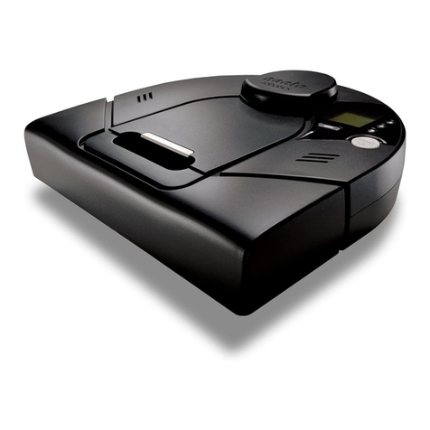
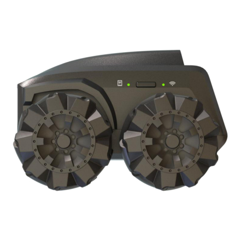
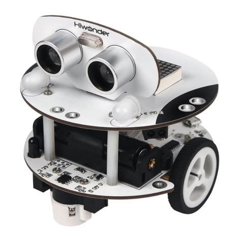
Hi-Tec MA-VIN User manual


About the manual
This manual is organized in order of level of difficulty and different uses of MA-VIN.
Precautions
This manual contains crucial information including the precautions that must be taken seriously to insure trouble free
operation of MA-VIN robot as well as prevent damage for the user and others. In addition, this user manual should be
placed in a place where it is accessible to as many users as possible.
When inner content of battery is accidentally put into one’s eyes, wash the eyes immediately with clean, flowing
water and follow the procedures given by a medical doctor.
It may cause serious damage to the eyes if kept untreated.
When inner content of battery is exposed to skin or clothes, make sure to wash with clean, flowing water.
It may cause damage to skin if put unwashed.
Do not dissemble or tamper with any part of the machine.
It might cause electrocution or damage due to malfunction of the machine.
Do not touch any inner part of the machine exposed due to external damage such as fall.
It might cause electrocution or damage on user. Take out the batteries and ask for professional help from Multiplex
Modellsport GmbH & Co.KG
Do not exert any extreme pressure on the machine.
It might cause damage or fire.
Do not apply any inflammable chemical such as benzene, paint thinner etc. Do not place any part of the machine
near naphthalene or camphor.
Plastic case might melt or cause fire and electrocution. When not in use, take out the batteries.
Keep parts away from any infant.
Make sure that batteries are inserted the right way round and with the correct polarity.
Do not mix new and used batteries or mix batteries of different types - always use a complete set of new
batteries of the same type when replacing batteries.
Do not recharge non-rechargeable batteries.
Use the correct charger for the size and type of rechargeable battery and always remove rechargeable batteries
from the toy before recharging them.
Remove exhausted batteries from the product.
In use of a power pack, we recommend to use only original power packs from Hitec/Multiplex, in other cases, we can not
take over warranty.
Specifications and Product Design are subject to change without prior notice
Before Reading the MA-VIN Manual
Our contemporary society is swiftly changing to accommodate not only the ever increasing amount of information but also
the ubiquitous intelligent machines. Constituents of the society now daily struggle to more efficiently handle the enormous
amount of information as well as better satisfy individual needs.
In this new era of ‘ubiquitous’ robots, intelligent robots will play a crucial part in improving people’s lives. The intelligent
robots, also referred to as ‘personal robots’, will therefore play a crucial role in our future society, altering our lifestyles,
cultures etc. Combining with already huge multimedia and IT industries, such robots are also expected to rise significantly
in their market values.
Hitec/Multiplex. is willing to take a bold step forward in order to accommodate such changes of our society. Based on our
R&D effort, we create market-based and human-friendly robots. We, as the forerunners in the field of anthropocentric
robotics, will incorporate the diverse contents from informatics, education and entertainment. We promise to bring the
technology together with a suitable market.
Thank you for purchasing the education robot, MA-VIN!

Exploded View / Explosionszeichnung

1 of 43
1. HOW TO ASSEMBLE MA-VIN BODY..................................................................................................................................... 3
1.1. HOW TO ASSEMBLE MA-VIN BODY ...................................................................................................................................... 3
2. MA-VIN COMPONENTS............................................................................................................................................................ 5
2.1. PRODUCT COMPONENTS ......................................................................................................................................................... 5
2.1.1. Components list................................................................................................................................................................. 5
2.1.2. MA-VIN Controller Body.................................................................................................................................................. 5
2.1.3. Input/Output Module Function ......................................................................................................................................... 6
2.1.4. How to Connect Modules.................................................................................................................................................. 7
2.1.5. Using Connection Port...................................................................................................................................................... 7
2.2. INSTALLING MA-VIN ROBOTICS LAB ............................................................................................................................... 8
2.2.1. Before Installing................................................................................................................................................................ 8
2.2.1.1. What is MA-VIN ROBOTICS LAB? .........................................................................................................................................8
2.2.1.2. MA-VIN ROBOTICS LAB User System Requirements............................................................................................................8
2.2.2. Installing........................................................................................................................................................................... 8
2.2.2.1. Installing USB to USB-UART Bridge Driver.............................................................................................................................8
2.2.2.2. Installing MA-VIN ROBOTICS LAB ........................................................................................................................................9
2.2.2.3. Installing USB Drive Manually.................................................................................................................................................12
3. BASIC USES OF MA-VIN ROBOTICS LAB.......................................................................................................................... 17
3.1. MA-VIN ROBOTICS LAB CONFIGURATIONS .................................................................................................................... 17
3.1.1. Screen Display ................................................................................................................................................................ 17
3.1.2. Menu Display.................................................................................................................................................................. 17
3.1.2.1. File(F) .......................................................................................................................................................................................17
3.1.2.2. Source(S) ..................................................................................................................................................................................19
3.1.2.3. Tool(T)......................................................................................................................................................................................19
3.1.2.4. View(V)....................................................................................................................................................................................20
3.1.2.5. Help(H).....................................................................................................................................................................................20
3.1.3. Modules : Logic Module, Branch Module, Output Module ............................................................................................ 21
3.1.3.1. Logic Module............................................................................................................................................................................21
3.1.3.2. Output Module..........................................................................................................................................................................22
3.1.3.3. Module Properties and Programming Result.............................................................................................................................23
3.2. PROGRAMMING IN MA-VIN ROBOTICS LAB (BASICS OF MOTION MODULE)................................................................... 23
3.2.1. Arranging Modules......................................................................................................................................................... 23
3.2.2. Converting Programming into Machine Language ........................................................................................................ 24
3.2.3. Downloading Compiled Program to MA-VIN................................................................................................................. 25
4. PROGRAMMING IN MA-VIN ROBOTICS LAB (BASICS OF MOTION MODULE)..................................................... 27
4.1. INSCRIBING LCD.................................................................................................................................................................. 27
4.1.1. Characteristics of LCD Module...................................................................................................................................... 27
4.1.2. Changing Parameters ..................................................................................................................................................... 27
4.1.3. Programming Completed; D/L to MA-VIN..................................................................................................................... 27
4.2. RINGING BUZZER.................................................................................................................................................................. 27
4.2.1. Characteristics of Buzzer Module................................................................................................................................... 27
4.2.2. Changing Parameters ..................................................................................................................................................... 28
4.2.3. Ringing Buzzer................................................................................................................................................................ 28
4.3. LIGHTING LED..................................................................................................................................................................... 28
4.3.1. Characteristics of LED Module ...................................................................................................................................... 28
4.3.2. Changing Parameters ..................................................................................................................................................... 28
4.3.3. Turning On/Off LED....................................................................................................................................................... 29
4.3.4. Turning On/Off LED Consecutively................................................................................................................................ 29
4.4. COUNT DOWN USING FND................................................................................................................................................... 29
4.4.1. Characteristics of FND Module...................................................................................................................................... 29
4.4.2. Changing Parameters ..................................................................................................................................................... 30
4.4.3. Count Down Using FND................................................................................................................................................. 30
4.5. RINGING MELODY (1)........................................................................................................................................................... 30
4.5.1. Characteristics of Speaker Module................................................................................................................................. 30
4.5.2. Changing Parameters ..................................................................................................................................................... 31
4.5.3. Ringing Different Kinds of Melodies............................................................................................................................... 31
4.6. RINGING MELODY (2)........................................................................................................................................................... 31
4.6.1. Characteristics of Compose Module............................................................................................................................... 31
4.6.2. Changing Parameters ..................................................................................................................................................... 31
4.6.3. Create Your Own Melody................................................................................................................................................ 32

2 of 43
4.7. MOVING MA-VIN................................................................................................................................................................ 32
4.7.1. Characteristics of Motor Module.................................................................................................................................... 32
4.7.2. Changing Parameters ..................................................................................................................................................... 32
4.7.3. Spinning MA-VIN in One Direction................................................................................................................................ 32
4.7.4. Move MA-VIN Forward/Backward/Right/Left................................................................................................................ 32
5. PROGRAMMING IN MA-VIN ROBOTICS LAB (BASICS OF SENSOR MODULE)...................................................... 33
5.1. MAKING DOORBELL USING TOUCH SENSOR (1)................................................................................................................... 33
5.1.1. Characteristics of Touch Sensor Module........................................................................................................................ 33
5.1.2. Changing Parameters ..................................................................................................................................................... 33
5.1.3. Doorbell Using Buzzer.................................................................................................................................................... 33
5.1.4. Doorbell Using Melody................................................................................................................................................... 34
5.1.5. Make Your Own Doorbell............................................................................................................................................... 34
5.2. ALARM CLOCK ..................................................................................................................................................................... 34
5.2.1. Ringing Melody after 10 Seconds.................................................................................................................................... 34
5.2.2. Ringing Melody in Daylight – Characteristics of CdS Module....................................................................................... 35
5.2.3. Changing Parameters ..................................................................................................................................................... 35
5.2.4. Making Alarm Clock....................................................................................................................................................... 35
5.3. BURGLARY ALARM .............................................................................................................................................................. 36
5.3.1. Characteristics of Microphone Module .......................................................................................................................... 36
5.3.2. Changing Parameters ..................................................................................................................................................... 36
5.3.3. Making Burglary Alarm.................................................................................................................................................. 36
5.4. REMOTE CONTROLLED MA-VIN.......................................................................................................................................... 37
5.4.1. Characteristics of Remote Control Module..................................................................................................................... 37
5.4.2. Changing Parameters ..................................................................................................................................................... 37
5.4.3. Changing FND Number Using Remote Control ............................................................................................................. 37
5.4.4. Remote Controlled MA-VIN............................................................................................................................................ 38
6. PROGRAMMING IN MA-VIN ROBOTICS LAB (APPLICATIONS OF FRONT/REAR MODULE)............................ 39
6.1. CHARACTERISTICS OF FRONT/REAR MODULE ...................................................................................................................... 39
6.1.1. Characteristics of Front/Rear Module............................................................................................................................ 39
6.1.2. Changing Parameters ..................................................................................................................................................... 39
6.1.3. Controlling FND Using Front/Back Module .................................................................................................................. 39
6.2. MA-VIN AVOID ROBOT....................................................................................................................................................... 40
6.2.1. Programming Avoid Robot ............................................................................................................................................. 40
6.3. MA-VINLINE TRACE ROBOT............................................................................................................................................... 40
6.3.1. Programming Line Tracer .............................................................................................................................................. 41
7. PROGRAMMING IN MA-VIN ROBOTICS LAB (USE OF APPLICATIONS MODULES)............................................ 42
7.1. APPLICATION MODULES....................................................................................................................................................... 42
7.1.1. Making Application Module............................................................................................................................................ 42

3 of 43
1. How to Assemble MA-VIN Body
1.1. How to Assemble MA-VIN Body
1. Check if you are missing any of the MA-VIN
components
2. Tighten the screws on the battery pack
3. Assemble the left gear box 4. Assemble the right gear box
5. Attach the cover to gear box 6. Screw the cover to the gear box

4 of 43
7. Attach the Front/Rear sensor
8. Take out the main board
9. Attach the main board to the body of MA-VIN 10. Screw the main board to the body
11. Connect LCD, power supply, motor etc. to the
body
12. Put the cover on the body

5 of 43
2. MA-VIN Components
2.1. Product Components
2.1.1. Components list
No. Components Qty. Usage
1 Main Board 1 Controls MA-VIN
2 Gear Box 2 MA-VIN driver motor
3 Battery Box 1 AAA 1.5V * 4
4 Front/Rear Sensor Module 1 Equipped with assistant wheels; perceives front/rear environment
5 LCD 1 Displays 2*8 letters
6 Wheels 2 MA-VIN driver wheels
7 USB Download Cable 1 Connector to PC
8 Case 1 External protection cover
9 Speaker 1 Plays melodies
10 Buzzer 1 Buzzes
11 FND 1 Displays 0~9, A, B, C, D, F
12 LED 1 Controls 4 LED’s
13 CDS 1 Perceives the light intensity
14 Touch Sensor 1 Perceives touch sense
15 Switch 1 1~7 switch input
16 Screw 14 Needed in assembling MA-VIN
2.1.2. MA-VIN Controller Body

6 of 43
No. Komponente Beschreibung
1 LCD display panel can be personalized. 2 lines, 8 letters each line,
total 16 letters can be displayed
2 POWER LED(Red LED) displays the status of power supply by DC 5V
3 Power switch turns on and off the power
4 DL Jack connects to download cable
5 Download LED(Green LED) displays the download status
6 Motor Connector connects DC motor to the MA-VIN body
7 Module Connector connects module to KIT(1~5)
8 IR Receptor receives remote control signal
9 Microphone perceives sound
10 Power Connector supplies DC 5V power
11 Power Jack supplies DC 5V power (when supplying power
with other adaptors)
2.1.3. Input/Output Module Function
1) Input Module
Typ Module Function
Switch Module
controls output according to Tact S/W
input
CdS Sensor Module
controls output according to light input
Touch Sensor Module
controls output according to touch sense
input
Microphone Module internally installed in KIT; controls output
according to sound input Schall
Front/Rear Sensor Module
installed in frame as a button; total 6 (front
3, rear 3) controls output
2) Output Module
Typ Module Function
Buzzer Module buzzes
FDN Module displays one digit number, depending on
input value
LED Module displays 4 LED output values
LCD Module displays 2 x 8 text
Speaker Module plays melody; plays 1.5 octave, 18 notes
DC Motor Module
controls output by connector time;
directional control; controls velocity by
variable resistance (optional category)

7 of 43
2.1.4. How to Connect Modules
a. Align the MA-VIN body and the module as shown in (picture) (texts on module and board aligned)
b. Plug the module into any of number from 1 to 5 of MA-VIN Body Module.
c. There are Buzzer Module, LED Module, FND Module, Speaker Module, Touch Sensor Module, CdS Sensor
Module, and Switch Module that could be plugged into MA-VIN Body Module.
d. LCD, Buzzer, Remote Control Receptor are already installed on MA-VIN Body. We currently do not provide
Remote Control Transmitter.
2.1.5. Using Connection Port
Program download cable is installed in the following steps:
a. Connect the USB cable to USB port of computer.
b. Connect the other end of USB cable to DL(Download) Jack of MA-VIN control board.
c. After programming in MA-VIN ROBOTICS LAB, download the program to MA-VIN.
d. Check the program in MA-VIN.

8 of 43
2.2. Installing MA-VIN ROBOTICS LAB
2.2.1. Before Installing
2.2.1.1. What is MA-VIN ROBOTICS LAB?
MA-VIN ROBOTICS LAB is a software for programming the movements of MA-VIN. Generally, controlled robots need to
be programmed in C programming language. However, such programming requires significant devotion of time and
effort. In order to make programming easier, we have created MA-VIN ROBOTICS LAB in GUI setting. Such icon-based
programming according to different kinds of modules has already made the robotics education experience much more
effective and fun.
2.2.1.2. MA-VIN ROBOTICS LAB User System Requirements
MA-VIN ROBOTICS LAB runs optimally under the following systems.
If lacking any, we recommend upgrading your system.
•200 MB hard-disk space
•100 MB hard-disk space
•256 MB or above RAM
•Intel Pentium III or above processor or compatible processors
•OS Microsoft Windows 2000, XP etc.
.
2.2.2. Installing
Installing MA-VIN ROBOTICS LAB starts with inserting the setup CD into CD-ROM. First install USB to UART Bridge
Driver
2.2.2.1. Installing USB to USB-UART Bridge Driver
Click USB to UART Bridge Driver • CP2101_Drivers.exe.
The window on the right will appear at the beginning of
the driver install process.
The initial screen disappears, and the window on the left
will show. Click ‘next’ to begin installing.
If you agree with license information concerning CP2101
USB to UART Bridge Controller, click ‘Yes’.

9 of 43
Select a folder to install CP2101 USB to UART
Bridge Controller Driver in. Click ‘Next’. Default
folder is “C:\SiLabs\MCU\CP2101”.
CP2101 USB to UART Bridge Controller is being
installed.
2.2.2.2. Installing MA-VIN ROBOTICS LAB
After CP2101 USB to UART Bridge Controller
Driver installation is complete, start MA-VIN
ROBOTICS LAB installation in following order.
Double click Setup.exe in MA-VIN ROBOTICS LAB Setup CD. Click “Next”

10 of 43
Enter your name and the name of your organisation and click “next”.
Select “Complete” Installation and click next. The default folder of installation is “C:\Program Files\MA-VIN”.

11 of 43
Click “Install”. MA-VIN ROBOTICS LAB is being installed.

12 of 43
Installation complete. Click “Finish”.
2.2.2.3. Installing USB Drive Manually
Control Panel • Add New Hardware

13 of 43
If your computer will automatically search for a new hardware to install and shows the CP2101 USB to UART Bridge
Controller Driver window as shown below, skip procedure 3)~6) and start from 7).
If your computer does not automatically search for a new hardware, manual install window as shown below will appear. If
MA-VIN is connected to the PC, select ‘Yes’ as below.

14 of 43
Select ‘CP2101 USB to UART Bridge Controller’ and click ‘Next>’
Install completed
After ‘Add Hardware Wizard’ is completed, ‘Found New Hardware Wizard’ as shown below will appear.

15 of 43
Select ‘(Advanced)’ and click ‘Next>’.
Select the folder that contains the drivers as shown below.
Check if the folder is the right one, and click ‘Next’.

16 of 43
Installing
Installing Hardware is completed when ‘Completing The Found New Hardware’ appears.

17 of 43
3. Basic Uses of MA-VIN ROBOTICS LAB
3.1. MA-VIN ROBOTICS LAB Configurations
3.1.1. Screen Display
1. Main Menu : contains “file”, “source”, “tool”, “view”, and “help”.
2. Tool Bar : icons of the selected menu options
3. Logic Module : includes branch modules and logic modules, such as sensors, needed for programming the
movements of MA-VIN.
4. Output Module : output module of MA-VIN; includes motor and LED modules.
5. Main View : space for programming MA-VIN
6. Module Properties : indicates module’s properties
7. Programming Result : displays MA-VIN ROBOTICS LAB programming process
8. Application Module : functions made by logic modules and output modules can be used as modules.
3.1.2. Menu Display
Knowing different menu options and tool bar buttons is the first step of learning programming. Each “file”, “source”, “tool”,
“view”, and “help” has its own menu within. Click the menu for its submenu. Using icon toolbar can ease the burden of
having to click through the submenus. Once you get used to using MA-VIN ROBOTICS LAB, toolbar will become much
handier than the menu. We will now talk about menu and toolbar buttons :
Main menu and toolbar are as shown as below. The most commonly used menu functions are in icons.
3.1.2.1. File(F)
New, Open, Save These are the most basic functions needed for programming. It opens a new file, opens a created file,
and saves a file.
Table of contents
