Hi-Tec Aurora 9 User manual

Hitec RCD Inc.
R/C Controller
Model No : AURORA9
P O W E R : 1. Poser supply from the AC/DC Adapter
input - AC 100 V~240V: 50Hz/60Hz
Output - TX : DC 7.2V : 80mA
RX : DC 4.8V: 80mA
2. Rechargeable Battery : Lithium-ion
Serial No : NONE
This device complies with part 15 of the FCC Rules.
Operation is subject to the following two conditions:
(1) This device may not cause harmful interference, and
(2) This device must accept any interference received,
including interference that may cause undesired operation.
2 3
9 CHANNEL 2.4GHz AIRCRAFT COMPUTER RADIO SYSTEM 9 CHANNEL 2.4GHz AIRCRAFT COMPUTER RADIO SYSTEM
Welcome to the Aurora experience!
The Aurora 9 is Hitecs most sophisticated R/C transmitter and allows the user to choose between 72MHz FM,
Hitecs QPCM and our new “Advanced Frequency Hopping Spread Spectrum” AFHSS 2.4GHz signal technology.
Hitec developers worked hard to deliver the easiest to program, most flexible 9 channel radio ever made.
The Aurora will fly almost any airframe conceived, heli, glider, glow, gas or electric powered plane. Best of all,
the programming is very rational and follows an extraordinary logical path.
We sincerely encourage you to read at least the first couple sections of the manual, as they contain invaluable
information created to make your experience with the Aurora a pleasant one.
Quick Start Guide to setting up a simple powered airplane or glider.
Quick Start Guide to setting up a Heli.
Introduction
Table of Contents
Content Disclaimer
Please note that Hitec reserves the right to make production changes during the life of our product lines that
may impact the information in this manual.
For the most up-to-date information on this and any other Hitec product, visit our web site at www.hitecrcd.com.
Introduction
Table of Contents
Steps for Aurora Programming Success
Using this Manual
Quick Set-up Guides
Aurora Software Architecture Explained
What’s New?
Product Support
System Component Specifications
Glossary of Terms
Icon Identification
Safety Information
Warnings
Transmitter Battery Information
Signal Modulation Options
SPECTRA PRO 72MHz FM PPM / 72MHz QPCM
Hitec 2.4GHz System Set-up
SPECTRA2.4 2.4GHz Module Features
Optima Series Receiver Features
Set-up and Use
Range Check Function
ScanMode Set-up
Failsafe
Telemetry System
SPC (Supplementary Power Connection) System
Aurora Transmitter Accessories
Aurora Transmitter Controls
The First Screen
Multi-I/O port
Home Screen Menu
System Menu Programming
Model Menu Programming
System Menu Programming
Model Menu Programming
2 - - - - -
3 - - - - -
6 - - - - -
7 - - - - -
8 - - - - -
9 - - - - -
9 - - - - -
10 - - - - -
11 - - - - -
13 - - - - -
14 - - - - -
15 - - - - -
18 - - - - -
22 - - - - -
23 - - - - -
27 - - - - -
28 - - - - -
30 - - - - -
34 - - - - -
38 - - - - -
41 - - - - -
Introduction
Section One
Section One
Section Two
Section Three
Manufacturer : HITEC RCD PHILIPPINES, INC
Made in Philippines

4 5
9 CHANNEL 2.4GHz AIRCRAFT COMPUTER RADIO SYSTEM 9 CHANNEL 2.4GHz AIRCRAFT COMPUTER RADIO SYSTEM
System Menu
MDL Select Create a new model
Select an existing model
Copy one models data into a fresh model memory slot
Reset the model memory to factory default settings
Rename a model
MDL Type Model type menu, ACRO, GLID or HELI
Timer Menu for Timer 1, 2 and the Integral timer
Channel Model control channel assignment menu.
Modulation Select desired modulation type, 2.4, 72 FM or QPCM
TrimStep Size adjustment menu for the trim steps
Trainer Trainer option menu
Power Transmitter power adjustment menu
MODE Stick mode option menu
Info Transmitter ID information
Freq Sel Select the active models transmit channel while in PPM and QPCM only
Sensor Telemetry menu appearing while in 2.4GHz mode only.
Model Menu and more…
Major Super Special Hints
Additional Menus, the Custom and Adjust Features
Adjustment Menu
The Switch Selection Process
Selecting a switch
The Adjust function switch set-up
Additional camber and launch mode adjust function menu (GLID)
Helicopter throttle and pitch curve adjust functions, hover trim and more
Trim link Activation
Cut position set-up
Launch cut switch set-up
Common Model Functions to ACRO, GLID and HELI
EPA End Point Adjustment
D/R & EXP Dual Rates and Exponential (expo) rates
Sub-Trim Servo Sub-trim adjustment
Reverse Servo reversing function
S. Speed Servo Speed feature
Monitor Active model control monitor
P. Mixs Programmable Mixing
FailSafe Servo position FailSafe
Gyro Gyro on/off and Sensitivity Adjustment
47 - - - - -
49 - - - - -
54 - - - - -
56 - - - - -
57 - - - - -
59 - - - - -
60 - - - - -
62 - - - - -
63 - - - - -
64 - - - - -
65 - - - - -
65 - - - - -
67 - - - - -
67 - - - - -
68 - - - - -
71 - - - - -
72 - - - - -
73 - - - - -
74 - - - - -
75 - - - - -
76 - - - - -
77 - - - - -
78 - - - - -
79 - - - - -
79 - - - - -
80 - - - - -
80 - - - - -
81 - - - - -
83 - - - - -
84 - - - - -
Model Menu
HELI Specific Functions
FLT.COND Idle-up and hold / Flight Conditions
P. & T. Curve Pitch curve & Throttle curve adjustment
Needle Carburetor needle function
SWH-THR Swash plate movement to throttle mix
RUD-THR Tail rotor to throttle mix
T. HOLD Throttle hold function
SwashMix Swash plate fine tuning menu
REVO Mix Revolution mix
Gyro Gyro functions
Governor RPM governor adjustment
Model Menu
Common Model Functions to ACRO and GLID
FLT.COND Flight Conditions
Airbrake Airbrake Function and Landing Mode.
ABR- ELE Airbrake to Elevator mix
AIL-RUD Aileron to Rudder mix
ELE-CAM Elevator to Camber mix
RUD-AIL Rudder to Aileron mix
AIL DIFF Aileron Differential feature
AIL- FLP Aileron to Flap mix
CAMBMIX Wing trailing edge mix
FLP CON Flap control mix
V.Tail V-Tail mix feature
AILEVATR Split elevator and aileron inclusion mix
Elevon Elevon or flying wing mix
Fuel Mix Fuel mixture control adjustment ACRO only
Thro.Cut Throttle cut position ACRO only
T.Curve Throttle curve ACRO only
IdleDown Throttle Idle down position ACRO only
B-fly Butterfly or “Crow” mix GLID only
SnapRoll Snap roll function ACRO only
Motor Glider motor control feature GLID only
Launch Launch mix GLID only
Section Four
Section Five
Section Six
Section Seven
86 - - - - -
91 - - - - -
92 - - - - -
94 - - - - -
95 - - - - -
96 - - - - -
97 - - - - -
98 - - - - -
99 - - - - -
100 - - - - -
101 - - - - -
102- - - - -
103 - - - - -
104 - - - - -
105 - - - - -
106 - - - - -
107 - - - - -
108 - - - - -
109 - - - - -
112 - - - - -
113 - - - - -
116 - - - - -
122 - - - - -
123 - - - - -
124 - - - - -
125 - - - - -
126 - - - - -
127 - - - - -
129 - - - - -
130 - - - - -
132 - - - - -

2 3
9 CHANNEL 2.4GHz AIRCRAFT COMPUTER RADIO SYSTEM 9 CHANNEL 2.4GHz AIRCRAFT COMPUTER RADIO SYSTEM
Using the Manual
It is NOT recommended that you read it cover to cover unless you have trouble falling asleep at night.
However, the manual will be a fine resource on the methods and programming details of the Aurora.
As you use the radio, use this manual!
The Aurora manual is divided into seven distinct sections;
1. Introductory material that is mandatory reading. This is where you will learn detailed
information that will be invaluable to successful Aurora programming.
2. Airplane/Glider quick start guide.
3. Heli quick start guide.
4. System menu programming common to all ACRO, GLID and HELI models.
5. Model menu programming common to ACRO, GLID and HELI models.
Additional menus and switch selection process
6. Model menu programming for ACRO and GLID models.
7. Model menu programming specific to HELI models.
Warning, Caution, Note and Tip Boxes
Throughout the manual you will see important information inside a labeled box. Take care to note this information.
Here’s a sample;
Quick Set-up Guides
We recommend that you read the introductory information in section one, then jump right into one of the quick start
guides and start programming. After following along with the quick start guide you will have a “feel” for the way the
Aurora’s programming architecture has been laid out. We encourage you to set-up a few aircraft before you fly the Aurora.
It will be time well spent and help smooth your passage along the programming learning curve.
Aurora Software Architecture Explained.
Unlike prior Hitec radios, the Aurora features “open” software architecture. Any function can be controlled by almost any
switch, slider, gimbal stick or button. To ease your way through the programming, many of the traditional channel choices
and control functions are used by default, until you get to the more sophisticated set-ups. By the time you graduate to
programming complicated models, you’ll be well schooled in programming your Aurora.
As you add more functional choices to a models programming, you may be called upon to tell the Aurora what switch
you would like to use for activating functions like retracts, gyros, dual and exponential rates, flight conditions and mixing
functions.
The Aurora is a powerful computer. Anyone who has used a computer will acknowledge the only way to really become
proficient with any software program is to use it. We at Hitec encourage you to invest several hours in setting-up various
airframes before you ever use the Aurora.
Take the time to familiarize yourself with the programming architecture. The flow of the programming will literally pull
you through the set-up process. You will find with a little practice, that within a short time you will master the Aurora’s
capabilities.
Steps for Aurora Programming Success
Many of you have owned or used earlier model Hitec transmitters. Here are seven “new” Hitec transmitter
features that set the Aurora apart from all other Hitec products.
1. Signal Protocol
Your Aurora can transmit three different signals, 72MHz FM, QPCM and 2.4GHz.
1. Using Hitecs AFHSS 2.4GHz module to link with Hitec Optima AFHSS 2.4GHz receivers.
2. Use the SPECTRA PRO, 72MHz frequency synthesizer module to fly any brand of 72MHz receiver, on any channel.
3. Select the Hitec QPCM signal option when using the SPECTRA PRO module to use the QPCM receiver on any channel.
2. Touch Screen Programming
Look at me, no buttons! Just press the icon or word on the screen to easily flow through the Aurora programming.
3. 72MHz Synthesizer
Use the new SPECTRA PRO module in your Aurora and select any of the fifty 72MHz channels through the Aurora software.
No more taking the module in and out of the radio to change your frequency.
4. Battery Management
The Aurora arrives with a six cell NiMH battery and 110V or 220V charger. It does have the option of using a six cell NiCd,
NiMH pack, or a 2 cell Li-Po battery. Using a Li-Po entails removing the battery from the transmitter for charging with an
appropriate charger.
5. Gimbals
Feel the silky smooth action of the new four ball bearing supported gimbals in the Aurora 9. These new gimbals were
created to give you the smoothest action demanded by the highest performance aircraft.
6. Switch Assignments
During the model programming steps you will be asked to select what stick, switch or slider controls the features you want
to use with your model. This gives you unlimited flexibility to choose the most comfortable and practical way for you to use
the Aurora.
7. Channel and Control Assignments
The Aurora will automatically select the channel and control assignments based on the model you have. There is the option
to change them if you wish, allowing you a wider choice of receivers that can be used with the Aurora.
What’s New?
6 7
If you are unable to accomplish a successful range check of 90 feet, DO NOT ATTEMPT TO FLY.
Warning
Warning Note
TipTipTip
Tip
Caution

8 9
9 CHANNEL 2.4GHz AIRCRAFT COMPUTER RADIO SYSTEM 9 CHANNEL 2.4GHz AIRCRAFT COMPUTER RADIO SYSTEM
Aurora Programming Support
While every attempt was made by the Aurora’s developers to make the software interface easy and logical, most users will
require programming help at some point. There are several “get help” options available to you.
Hitec Customer Service
Help is available from the Hitec office through phone support and e-mail inquiries. The U.S. office is generally open
Monday thru Friday, AM 8:00 to PM 4:30 PST. These hours and days may vary by season. Every attempt is made to answer
every incoming service call. Should you get voice mail, leave your name and number and a staff member will return
your call.
Hitec Web Site
Make plans to visit the Hitec web site on a regular basis, www.hitecrcd.com or www.hitecaurora.com. It is full of specs
and other information about the entire Hitec product line, and our FAQ pages will eventually hold valuable information
about the Aurora.
The On-Line Community
One of the benefits of the extensive R/C online community is the vast wealth of archived knowledge available. Hitec
sponsors forums on most of the popular R/C web sites where a Hitec staff member or representative tries to
answer all manner of product related questions. Bringing together strangers with common interests is proving to be
one of the greatest gifts of the internet. If past history is any guide to the future, we are certain forums will be started
about the Aurora and several are sure to stand out as valuable archives of information.
Warranty and Non-Warranty Service
All Hitec products carry a two year from date of purchase warranty against manufactures defects. Our trained and
professional service representative will determine if the item will be repaired or replaced. You say the 4 year old kid
knocked your Aurora off a table? Hitec has an in-house service department to fix our products quickly.
To provide all the necessary information we need to administrate your repair, visit our web site at, www.hitecrcd.com
and download the repair form, fill it out and send in your item for repair.
Hitec Service
12115 Paine St.
Poway CA 92064
1-858-748-6948
E-mail, service@hitecrcd.com
AFHSS 2.4GHz signal Hitec 2.4GHz R/C signal protocol. Adaptive Frequency Hopping Spread Spectrum.
SPECTRA PRO Module 72MHz FM signal synthesizer module used with the Aurora.
SPECTRA 2.4 Module Hitec 2.4GHz module used with the Aurora.
Optima Receiver Hitec 2.4GHz receiver brand.
Telemetry Data signal from the model, transmitted to the transmitter.
Normal Mode Hitec 2.4GHz transmission signal choice.
Scan Mode Hitec 2.4GHz transmission signal choice.
link(ID Setting) Linking or “binding” a 2.4GHz receiver to its master transmitter.
QPCM Hitec “Pulse Code Modulated” 72MHz FM signal technology.
HPP-22 PC interface Aurora PC interface accessory.
Multi-I/O format File sharing, trainer and PC interface mode.
OST Offset curve feature
EXP Exponential rate curve feature
Delay Function initiation speed adjustment
Product Support
Note that the Aurora is available in several different system configurations. Here are the specs for the most
common equipment available for the Aurora. For more information on these and other Hitec product specifications
visit the web site at, www.hitecrcd.com.
Aurora 9 Transmitter
Modulation
AFHSS 2.4GHz w/SPECTRA 2.4 Module
72MHz PPM w/SPECTRA PRO Frequency Synthesizer Module
72MHz QPCM w/SPECTRA PRO Frequency Synthesizer Module
Power Supply : 7.2V NiMH Battery
Current Drain : 300 mA
System Component Specifications
Glossary of Terms
Optima 2.4GHz Series Receiver
Rx. Model Size Weight Stock Number
- Optima 6 1.65 x 0.82 x 0.44in (42 x 21 x 11.4mm) 0.52oz (15g) 28410
- Optima 7 2.24 x 0.82 x 0.44in (57 x 21 x 11.4mm) 0.60oz (17g) 28414
- Optima 9 1.85 x 1.12 x 0.44in (48 x 28.5 x 15.3mm) 0.77oz (22g) 28425
Operating Voltage : 4.8~7.4V From a receiver battery, or a speed control (ESC) power
4.8~35V Using SPC function
Current Drain : 190mA

10 11
9 CHANNEL 2.4GHz AIRCRAFT COMPUTER RADIO SYSTEM 9 CHANNEL 2.4GHz AIRCRAFT COMPUTER RADIO SYSTEM
Flying models can be dangerous if proper safety precautions are not followed. Here are a few critical safety
suggestions to keep you and others safe.
Are you experienced?
Flying models is not an intuitive process. Most accomplished model pilots were taught by another modeler. We encourage
you to seek help during your early flight experiences and if required, during the building and gear installation process. Unlike
some other hobbies, model airplane flying has evolved into a social event. There are approximately 2,500 model aircraft clubs
in America. Friendship and help could be right around the corner. Ask your local hobby shop about clubs in your area.
Where to Fly
Having enough land for your own model airport is rare. Most of us fly at club administrated model fields. The local ball field
can be tempting but rarely has the space needed and your liability is high should you damage property or hurt an innocent
person. We recommend you fly at a sanctioned model aircraft field.
Join the AMA
In America, the Academy of Model Aeronautics (AMA) is an organization of model enthusiasts that provide resources and
insurance to modelers. The AMA also lobbies the Government concerning legislation that impact modelers.
Visit their web site for more information, www.modelaircraft.org.
Academy of Model Aeronautics
5151 East Memorial Drive
Muncie, Indiana 47302
Toll Free : 800 435-9262
Fundamental Guidelines for Safe Flying
1. Don’t fly over people or personal property.
2. Make sure you do a range and pre-flight check on your aircraft.
3. Check for others flying on your frequency. (No need with 2.4GHz)
4. Know your batteries condition. Keep them charged.
5. The equipment we use in the R/C hobby is sensitive electronic gear. Have receivers checked after a crash before using
them in another aircraft.
6. Use the Fail-Safe function in AFHSS and QPCM mode to lower the throttle in case of a signal “lock-out”.
7. Don’t fly alone.
Safety InformationIcon Identification
Icon Identification
MODEL
The model menu contains the model programming for the active model.
ACRO
Menu for fixed wing, glow, gas and some electric models.
GLID
Menu for gliders and some electric models.
HELI
Menu for rotary wing aircraft.
EXIT DOOR
Appears in the upper right corner, the “go back” icon.
FOLDER
The custom menu. Often used, or “quick access” feature folder.
WRENCH
The system menu contains model set-up and transmitter feature menus.
ADJUST
The adjustment menu contains the adjustment features for quick access.
AILE
Aileron for fixed wing menus and the “roll” swash input for helis.
ELEV
Elevator for fixed wing menus and the “pitch” swash input for helis.
RUDD
Rudder for fixed wing menus and the “yaw”, or tail rotor input for helis
.
1/2, 1/3, 1/6 FRACTIONS
Indicates the number of pages in the menu. Press to access the next page.
+ RST –
Often used Aurora menu value input icons. Value adjustment icon
+
/
–,
RST : Reset
Arrow
Press to cycle through menu options.
C
Combination icon. Flight mode option, “groups” the flight mode values.
S
Separate icon. Flight mode option, “separates” the flight mode value.
INH
Inhibit is used to “turn off” a function.
SEL
Select is used to “select” a feature of the displayed menu.
ACT
Active, “turns on” a function.
NULL
“No switch” selected, the function or feature will be “on” all the time.
AUX
An “open” channel, without a control assigned to it.
J1
Right gimbal, up and down control.
J2
Right gimbal, side to side control
J3
Left gimbal, up and down control.
J4
Left gimbal side to side control.
T1
J1 control trim.
T2
J2 control trim.
T3
J3 control trim.
T4
J4 control trim.
LT
Left VR switch.
CT
Center VR switch.
RT
Right VR switch.
RS
Right slider control.
LS
Left slider control.
Multi-I/O
File sharing, trainer and PC interface mode.
DataTran
User can up / down load model setup data thru a PC.
T.Pupil
Aurora in pupil, or training mode
.

12 13
9 CHANNEL 2.4GHz AIRCRAFT COMPUTER RADIO SYSTEM 9 CHANNEL 2.4GHz AIRCRAFT COMPUTER RADIO SYSTEM
The Aurora has a few warning alarms you need to be aware of.
If the transmitter should start a continuous beeping during a flight, land immediately and evaluate the cause of the warning.
Low transmitter battery tone
When the transmitter battery power descends to a critically low level, a warning beeping will occur.
Low aircraft battery tone when using 2.4
If the aircrafts on-board battery is critically low, SPECTRA 2.4 Module will start beeping during its operation.
Start-up warnings
High Throttle
If the throttle is positioned above idle
during the system “boot-up to transmit”
process, a warning beeping will occur
and the following warning screen will
be displayed;
Condition warning at start-up
If you have flight conditions and other
mixing programmed for the active model,
and they are switched “on” during the
“boot-up to transmit” process, a warning
beeping will occur and the following
warning screen will be displayed;
Transmitter Battery InformationAurora Transmitter Warnings
In flight warnings
Lower the throttle to proceed.
Turn the mixes off to proceed.
Your Aurora transmitter is supplied with a rechargeable, 6 cell, AA size, 2000mAh Nickel Metal Hydride(NiMH)
Eneloop battery pack with a nominal voltage of 7.2V.
Charging
The preferred charging method is to use the supplied CG-S45 overnight wall charger. Plug it into the port as shown in the
diagram. Note the red “charging in process light” on the CG-S45 overnight wall charger. This light will turn green when
charging is complete. Normal procedure is to charge overnight before flying the next day.
Do not install a Li-Po in the Aurora and then try and charge it with the supplied CG-XX overnight wall charger.
The CG-XX was created for NiMH cells only! Certain major damage is sure to occur.
Caution
The battery can be removed from the radio and charged with a “quick” charger.
The recommended charge rate should be no more than 2 Amps.
Power Meter
There are two ways to review the battery voltage on the Aurora home screen. A “direct voltage read out”, and a “percentage
of available power” graph can be displayed by touching the power icon on the main menu.
The Li-Po Option
The nominal voltage of a two cell Li-Po or Lithium Polymer battery pack is 7.4V. The user has the option to power the Aurora with a 2S
Li-Po but accepts full responsibility to do so safely. To use a Li-Po transmitter battery safely, you must remove the battery from the
transmitter case for charging, and reinstall it after charging.
* Warning: During the Aurora 9's charging process, turn off the transmitter power

14 15
9 CHANNEL 2.4GHz AIRCRAFT COMPUTER RADIO SYSTEM 9 CHANNEL 2.4GHz AIRCRAFT COMPUTER RADIO SYSTEM
The Aurora offers the option to use the SPECTRA PRO 72MHz module for 72MHz operation, or SPECTRA 2.4 AFHSS
module for 2.4GHz operations. Please read the following text that explains the installation and set-up process for
these two options.
SPECTRA PRO 72MHz
With the SPECTRA PRO frequency synthesizer module, you choose what 72MHz channel you want to use for any of the
thirty model memories in the Aurora.
SPECTRA PRO Compatibility
Receiver Compatibility
When used in the Aurora, the SPECTRA PRO will fly models using any brand of 72MHz FM PPM receiver, or the Hitec QPCM receiver.
Transmitter Capability
The SPECTRA PRO will work in the Aurora transmitter only! As of this writing, it is not compatible with any other current R/C product.
Installation of the SPECTRA PRO
a. To install the SPECTRA PRO module, make sure the power is OFF.
b. Fit the SPECTRA PRO into the module pocket in the back of the Aurora radio case.
c. Line-up the pins with the mating connector and gently plug it in until the module is properly seated in the radio case.
How to use the SPECTRA PRO
There are several ways to change a models frequency in the Aurora.
For detailed instructions on changing the channel, consult page 57, the System menu, Freq Sel function.
1. At the very first screen,
by pressing the channel icon.
2. At the home screen by pressing the
CH-XX icon.
3. In the System menu, Freq-Sel menu.
Signal Modulation Options
In all cases shown below, PPM or QPCM must be selected as the radios signal modulation.
Note
SPECTRA 2.4GHz Module Features
The following contains the complete instructions on how to use the Optima 2.4GHz series receivers and SPECTRA 2.4GHz
module set for a trouble free 2.4GHz signal. We encourage you to review this information before using these products.
Optima Series Receiver Features
As of this writing, there are three Optima 2.4GHz receivers that are compatible with the SPECTRA 2.4GHz module.
The Optima 6, Optima 7 and the Optima 9 channel products are loaded with a variety of functions that are sure to
deliver a satisfying R/C experience.
1. Dual Blue and Red Status indicator LED’s
Indicates the set-up process codes and use status.
2. Function Button
Used for Linking(ID -Setting) the module to a receiver, entering the power down mode for range checks and the Nomal / Scan
Mode set-up.
3. Sensor Data Output and System Upgrade Connector Port
A 3 pin servo plug connector port is featured on the 2.4GHz module. Using the HPP-22 PC interface accessory this port serves to
facilitate upgrading the devices software and downloading information from Optima 7 and 9 channel receiver if using optional
onboard sensor station.
4. Adjustable Antenna
The antenna is an adjustable two piece unit hardwired to the module.
1. Telemetry Sensor and System Port
A three pin servo plug connector port is featured on the Optima 7 and 9 ch. receivers. Using the HPP-22 PC interface accessory this port
serves to facilitate upgrading the devices software and interfacing the optional onboard sensor station.
2. Function Button
Used for Linking(ID-Setting) the receiver to a module, entering Fail-Safe / Hold mode setup function.
3. Dual LED Status Indicator
Indicates the set-up process codes and use status.
Hitec 2.4GHz System Set-up
3-1.
Sticker Seal
4. Antenna
2. Function Button
3. Sensor Data Output &
System Update Port
1. LED

16 17
9 CHANNEL 2.4GHz AIRCRAFT COMPUTER RADIO SYSTEM 9 CHANNEL 2.4GHz AIRCRAFT COMPUTER RADIO SYSTEM
Optima Receiver Connection Diagrams
4. SPC Supplementary Power Connection
Power the Optima receiver function with up to a 35V. motor battery. Details about the SPC system can be found on page 21.
5. Channel Output and Battery Input Ports
The ports for battery power, servos, gyros and other accessories are located at each end of the streamlined Optima receivers.
6. Jumpers
The jumper is installed at the factory and is used when the receiver is powered by an electronic speed control,
a commercially available B.E.C. (battery eliminator circuit), dedicated 4.8 to 6V. NiMH battery pack, or *2S Li-Po/Io/Fe batteries.
The jumper is removed when the receiver is powered using the SPC feature as described in more detail on page 21.
Compatibility
The Optima series receivers are compatible with transmitters using the Hitec AFHSS 2.4GHz system Spectra 2.4GHz module or
dedicated non-module AFHSS Hitec transmitters in the future.
Normal / Scan Mode Selectable
Select between two operational signal types. See page 19 for details.
FAIL-SAFE Option
Servos and other accessories may be programmed with a FAIL-SAFE point in the event power to the receiver is interrupted.
See page 19 for details.
Onboard Receiver Battery Warnings
Know when your on-board battery is low with direct telemetry feedback to your transmitter. See page 21 for details.
Hitec 2.4GHz System Set-up Hitec 2.4GHz System Set-up
Warning
1. Function Button
2. Dual LED Status Indicator
3. Channel Output and Battery Input Ports
4. SPC (Supplementary Power Connection)
5. Telemetry Sensor and System Port
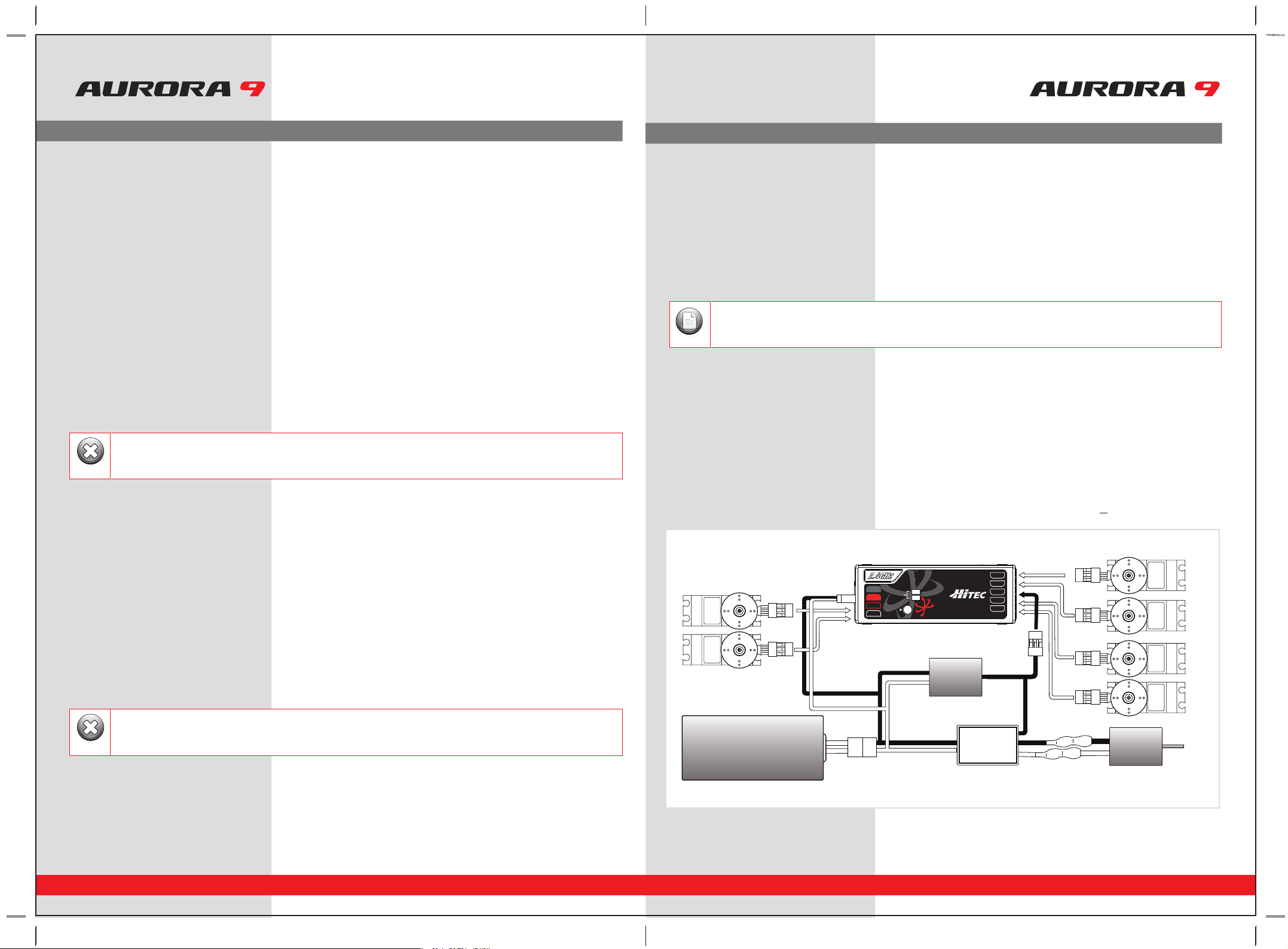
Electric powered aircraft with Electronic Speed Control
Use this method on electric planes using ESC’s providing power to the receiver and servo functions.
Optional BEC shown in diagram is used if the servo power requirements exceed that which the ESC provides.
SERVOSERVO
SERVOSERVO
SERVO SERVO
Power Battery Motor
BEC
ESC
Glow, gas or electric powered aircraft using a separate receiver battery supply.
Follow this connection diagram when using a dedicated 4.8 to 6V. NiMH battery pack, or *2S Li-Po/Io/Fe batteries.
BAT/CH7
CH6
DATA
SPC
LEDLED
LINKLINK
LED
LINK
CH1
CH2
CH3
CH4
CH5
OPTIMA OPTIMA 77OPTIMA 7
2.4GHz 7 Channel Aircraft Receiver2.4GHz 7 Channel Aircraft Receiver2.4GHz 7 Channel Aircraft Receiver
AFHSS
2.4GHz
Telemetric
ADAPTIVE
FREQUENCY HOPPING
SPREAD SPECTRUM
BAT/CH7
CH6
DATA
SPC
LEDLED
LINKLINK
LED
LINK
CH1
CH2
CH3
CH4
CH5
OPTIMA OPTIMA 77OPTIMA 7
2.4GHz 7 Channel Aircraft Receiver2.4GHz 7 Channel Aircraft Receiver2.4GHz 7 Channel Aircraft Receiver
AFHSS
2.4GHz
Telemetric
ADAPTIVE
FREQUENCY HOPPING
SPREAD SPECTRUM
SERVOSERVO
SERVO
SERVO SERVO
Receiver
Battery
SERVO
Engine
5
4
3
3
2
1
1
1
2
2
3
4
4
5
*Verify your servos are rated for use with these higher voltage batteries or use a regulator.
Warning
*Verify your servos are rated for use with these higher voltage batteries or use a regulator.

18 19
9 CHANNEL 2.4GHz AIRCRAFT COMPUTER RADIO SYSTEM 9 CHANNEL 2.4GHz AIRCRAFT COMPUTER RADIO SYSTEM
Set-up and Use of the Hitec 2.4GHz System
ID-Setup A.K.A, binding or linking
Binding when Transmitter is in Normal Mode
a. For the Aurora, turn on the transmitter. Press and hold the button on the module, and press Transmit Yes, red LED will flash,
release the button.
b. Press and hold the button on the receiver, turn on the receiver, red LED is on solid, release the button on the receiver.
After receiver is powered-up, the red LED glows solid and the blue LED flash’s on the module.
c. Turn off receiver.
d. Turn off transmitter.
e. Turn on transmitter, red LED is solid.
f. Turn on receiver, red LED is solid, after a moment the module will beep 4 times very quickly
g. You should now have control over the model as the transmitter and module are linked in Normal Mode.
Binding when Transmitter is in ScanMode
a. For the Aurora, turn on the transmitter. Press and hold the button on the module, and press Transmit Yes,
red LED will flash, release the button.
b. Press and hold the button on the receiver, turn on the receiver, red LED is on solid, release the button on the receiver.
Solid red and blue LEDs indicator that the receiver is linked with the module.
c. Turn off receiver.
d. Turn off transmitter.
e. Turn on transmitter, red LED is solid, blue LED is blinking.
f. Turn on receiver, red LED is solid, after a moment, the blue LED will also come on, and the module emits one long beep.
g. You should now have control over the model as the transmitter and receiver are bound in Scan Mode.
Each system and module / receiver set is paired at the factory for your convenience. Use the following Linking (ID-Setting)
sequence as you add Optima receivers into other aircraft to be controlled by your Aurora.
Note
- Binding must be done within 15ft. (5m) of the transmitter and receiver.
- Transmitter and receiver need to be at least 18in. (45cm) from each other to binding properly.
- In the ScanMode, if the transmitter or receiver has been shut off or disconnected for more than one second,
both module and receiver need to re-boot (turn the power off, and back on).
Note
To turn the system on and off, use the following sequence at all times
Turning On -Turn on the transmitter, select “transmit”, then turn on the receiver.
Turning Off -Turn off the receiver, then turn off the transmitter.
Warning
Always do a pre-flight function check
Before the engine or motor is started, turn on the system as explained above. Then make sure all the servos and control surfaces are
working properly. If any control surface is not moving properly, do not fly the aircraft until the problem is solved.
Range Check
Do a complete range check as described on page 20 before each flying session to confirm the radio system is working properly.
Your Hitec AFHSS system uses a communication protocol that links and binds the Optima receiver to your Aurora transmitter. Once their
ID is set, no other transmitter can interfere with your receiver during its operation. In the case of multiple model memory transmitters like
the Aurora, you can bind or link as many Optima receivers to your transmitter as necessary.
Normal Mode
- In this mode the receiver/transmitter uses the frequencies which selected at the time it was initially set-up.
- After the initial set-up, the everyday start-up is quicker in the Normal Mode. In 90% of cases the Normal Mode is preferred by users.
- In the Normal mode, if the transmitter or receiver loses power, then power is restored, the system will re-link and function normally.
- The factory default setup is Normal Mode.
Scan Mode
- In ScanMode the receiver/transmitter will scan all available channels every time you turn it on. It will then choose the cleanest
frequencies to use. ScanMode is preferable to use when flying in a crowded 2.4GHz environment.
- While in ScanMode if the transmitter loses power it will not rebind to the receiver, if the receiver loses power it will take longer
to re-bind than when in Normal Mode.
- In all cases the ScanMode binding function will take longer than in Normal Mode when you boot-up the system.
Changing from Normal Mode to Scan Mode
a. Turn on transmitter, then the receiver.
b. After linking and you have control over the model, press the button on the module for 6 seconds, you will hear one beep
followed by two beeps then release the button.
c. The module will now switch to ScanMode noted by the red and blue LED and one beep.
d. Turn off the transmitter and receiver.
e. Turn the system back on and wait for the system to boot and you have control over the model in ScanMode.
Changing from Scan Mode to Normal Mode
a. Turn on transmitter, then the receiver.
b. After linking and you have control over the model, press the button on the module for 6 seconds, you will hear one beep
followed by two beeps then release the button.
c. The module will now switch to Normal Mode noted by the red LED and two beeps.
d. Turn off the transmitter and receiver.
e. Turn the system back on and wait for the system to boot and you have control over the model in Normal Mode.
Set-up and Use of the Hitec 2.4GHz System
Scan Mode and Normal Mode Selection
Hitecs Spectra 2.4GHz module and Optima series receivers have two different operational modes to choose from,
“Normal” or ScanMode.
There are available 2.4GHz channels that can be used by your Hitec AFHSS 2.4 system. The following will explain
how Normal Mode and ScanMode use the channels.
FAIL-SAFE and Hold Mode
If you use the FAIL-SAFE function, and set it up properly, should the receiver signal somehow be interrupted or
interference were to occur, the servos will move to your pre-set FAIL-SAFE point you previously stored in the
receiver during the FAIL-SAFE set-up process.
If FAIL-SAFE has not been activated, the signal is switched off after the HOLD period of 1 sec. This means that the
servos become “soft” and remain in their last commanded position under no load (this may equate to full-throttle!),
until a valid signal is picked up again.
In the interests of safety, we recommend that FAIL-SAFE should always be activated, and the FAIL-SAFE settings
should be selected so as to bring the model to a non-critical situation (e.g. motor idle / electric motor OFF,
control surfaces neutral, airbrakes extended, aero-tow release open, etc).
20 21
9 CHANNEL 2.4GHz AIRCRAFT COMPUTER RADIO SYSTEM 9 CHANNEL 2.4GHz AIRCRAFT COMPUTER RADIO SYSTEM
Telemetry System
Currently there are two direct feedback telemetry functions available in your Hitec 2.4 system. Plans are to have many more
devices available in the future. Check the Hitec web site at www.hitecrcd.com for more up-to-date information.
I. Low Battery Warning
The 2.4 system will automatically recognize the receiver battery voltage among 4 and 5 cell NiMH or Nicad packs and 2S Li-Po/Io/Fe
batteries packs.
- When battery level is high (4 cell > 4.5V, 5 cell > 5.6V): The red module LED glows constantly.
- When battery level is low (4 cell < 4.5V, 5 cell < 5.6 V): blue LED glows constantly and the red LED will blink fast.
You will hear a continuous loud beep from the module as a low receiver battery warning. Upon hearing the alarm, we advise you to
land at once.
SPC (Supplementary Power Connection) System
Hitecs exclusive optional receiver power system allows you to directly power the receiver from the main motor power battery of
an electric powered aircraft. Up to 35 Volts can be fed directly into the receiver to power JUST THE RECEIVER FUNCTION. It will not
power the servos. Almost all servos will burn-up if more than 6 Volts are used over a short period of time.
Note; some Hitec servos are rated to be used at 7.4Volts. You will still need to supply power for your servos with a four or
five cell NiMH receiver battery, 2 cell Li-Po and regulator set-up, or a commercially available BEC. The SPC system was partially
created to be integrated into future Hitec telemetry system devices. Check the Hitec web site for more information on the availability
of telemetry systems in the future.
SPC Receiver Connection Diagram
Set-up and Use of the Hitec 2.4GHz System
FAIL-SAFE Setup
a. Switch on the transmitter, then the receiver, wait for the system to boot and you have control over the model.
b. Press and hold the receiver function button for 6 seconds, release the button. After 2 more seconds both red and blue
LEDs blink rapidly.
c. From the moment you release the button, the receiver will count 5 seconds during that time move all the transmitter sticks
and other controls to the desired FAIL-SAFE positions (e.g. motor idle, control surfaces neutral), and hold them there.
d. After 5 seconds the system will save the FAIL-SAFE position. Relax all the control sticks.
e. Turn off the receiver, then the transmitter.
f. Turn on the system to use it. FAIL-SAFE is now activated.
Testing the FAIL-SAFE Setting
a. Move the sticks to positions other than the FAIL-SAFE settings, and then switch off the transmitter. The servos should now
move to the FAIL-SAFE positions previously stored, after the HOLD period (1 sec.) has elapsed.
How to turn FAIL-SAFE Off and reactivate the Hold Mode
a. Switch on the transmitter, then the receiver. Wait for the system to boot and you have control over the model.
b. Press and hold the receiver function button for 6 seconds and release it. After 2 seconds the red and blue LEDs will blink rapidly.
c. Immediately press the button and release it.
d. FAIL-SAFE Mode is now deactivated and HOLD mode is activated.
e. Turn the transmitter off, then the receiver off.
f. Turn the system back on to use it.
Range Check Function
It is critical that before each flight session you perform a range check that confirms the signal between the receiver and transmitter is
appropriate. Unlike the FM/PPM or PCM signal radios, 2.4GHz systems use a fixed shorter, stubby transmitter antenna so the traditional
method of range checking your system by lowering the transmitter antenna will not work.
We instead use a power-down mode to reduce the transmitter signal strength. Once the power-down mode is activated it runs for about
90 seconds, shortening the effective range 100 feet (30 m). During this power-down mode that you should walk away from the secured
aircraft carrying the transmitter to a distance of approx. 30 meters, testing the effective range.
How to use Power-Down
a. Press the button on the module for 3 seconds, then both the blue and red LEDs will turn on with single beep sound. Release the
button. The 90-second countdown starts from the time the button released.
b. Walk away from the secured aircraft carrying the transmitter to a distance of approx. 100 feet (30 m), testing the effective range.
c. To exit the power-down mode before the 90 seconds, press the button again to escape.
Set-up and Use of the Hitec 2.4GHz System
- If FAIL-SAFE is deactivated, the FAIL-SAFE position settings are also deleted!
- The FAIL-SAFE settings should be checked every time before you run the engine/motor.
Warning
If you are unable to accomplish a successful range check of 90 feet, DO NOT ATTEMPT TO FLY.
Warning
BAT/CH7
CH6
DATA
SPC
LEDLED
LINKLINK
LED
LINK
CH1
CH2
CH3
CH4
CH5
OPTIMA OPTIMA 77OPTIMA 7
2.4GHz 7 Channel Aircraft Receiver2.4GHz 7 Channel Aircraft Receiver2.4GHz 7 Channel Aircraft Receiver
AFHSS
2.4GHz
Telemetric
ADAPTIVE
FREQUENCY HOPPING
SPREAD SPECTRUM
SERVOSERVO
SERVOSERVO
SERVO SERVO
Power Battery Motor
BEC
ESC
The low battery voltage warning can be custom programmed with the HPP-22
Note
Other manuals for Aurora 9
1
Table of contents
Other Hi-Tec Transmitter manuals


