Metal Samples MS2500E User manual

MS2500E Transmitter
Operator’s Manual
Metal Samples Company
A Division of Alabama Specialty Products, Inc.
152 Metal Samples Rd., Munford, AL 36268 Phone: (256) 358-4202 Fax: (256) 358-4515
E-mail: [email protected] Internet: www.metalsamples.com

.

Table of Contents
I. General Description ........................................................................................................ 1
A. Introduction .............................................................................................................. 1
B. General Description.................................................................................................. 1
C. Principles of Operation............................................................................................. 2
D. Technical Specifications........................................................................................... 3
II. InstallationandOperation.................................................................................................. 4
A. ReceivingtheMS2500ETransmitter ........................................................................... 4
B. Installation .................................................................................................................. 4
1. MechanicalMounting............................................................................................ 4
Figure1. PreferredInstallation ........................................................................... 5
2.ElectricalConnection .............................................................................................. 5
C. SafeAreaWiring ........................................................................................................ 6
D. HazardousAreaWiring............................................................................................... 6
1. ProbeSelectionTerminals ..................................................................................... 7
2. Calibration............................................................................................................ 7
Figure2. CalibrationConnections ...................................................................... 8
Figure 3. Switch Locations................................................................................ 9
3. Operation ............................................................................................................. 9
Figure4.Output LinearRelationship .................................................................. 10
4. DeterminingCorrosionRate .................................................................................. 10
E. SelectingtheProbe ..................................................................................................... 10
1. ProbeReplacementCalculation............................................................................. 10
F. Maintenance ............................................................................................................... 11
G. ReturningtheInstrumentforRepair ............................................................................. 12
III. MaintenanceandRepairInstructions.................................................................................. 13
IV. WarrantyInformation ........................................................................................................ 15

.

1
I. General Description
A. Introduction
The development of the MS2500E Transmitter provides the corrosion engineer with a simple,
lowcost, computer-compatible corrosion monitoring instrument. Designed to be incorporated into
a 20 mAcurrent loop, the MS2500E Transmitter uses the principle of electrical resistance to deter-
mine the corrosion rate of a metal specimen immersed in a process stream. The electrical resis-
tance of a metal specimen is a physical property dependent on the specimen’s physical dimensions
(length and cross section) and on the metal’s inherent resistivity. If all other factors remain con-
stant, any decrease in the cross section of a metal specimen will increase its resistance.
The MS2500E Transmitter is used in process systems for which appropriately designed electrical
resistance probes are available. Such systems include, but are not limited to nonaqueous, noncon-
ductive process streams, process streams where erosion-corrosion occurs and process streams
having either a predominant liquid or vapor phase. Examples of industries where such process
streams are found include chemical plants, refineries, gas plants, oil and gas production systems,
paper mills, power plants and tank farms.
B. General Description
The MS2500E Transmitter provides a two-wire interface between a single electrical resistance
probe and a customer-supplied process computer, recorder, or control system, or between a probe
and the MS2510 Receiver (ordered separately). The MS2510 Receiver and the MS2500E Trans-
mitter function together as a stand-alone, single-station monitoring system.
The current loop connecting the Transmitter and the data receiving station may be up to 11 miles in
length for circuits that do not include safety barriers and up to 1 mile for intrinsically safe circuits
(circuits that do include safety barriers or their equivalent). A customer-supplied DC power source
energizes the monitoring system. Probe signals representing metal loss are processed by the Trans-
mitter and are relayed to the data receiving station as a 4-20mA signal.
Unlike similar devices available from other manufacturers, the MS2500E Transmitter does not
require factory modification to accommodate different probe types.Asimple field calibration pro-
cedure permits the MS2500E to be used with any electrical resistance probe. The MS2500E will
accommodateall MetalSamples electricalresistance probesand mostof theelectricalresistance probes
ofothermanufacturers.
The MS2500E Transmitter is available in one enclosure style. This style is mounted on any flat
surface up to 5 feet from the probe and is connected to the probe via a special cable, model
Cb-8140 (included).

2
C. Principles of Operation
Electrical resistance probes contain a continuous sensing device that is divided into “elements”
connected in series. These elements include a measuring element and a reference element. The
measuring element is exposed to the corroding environment. The resulting loss of metal de-
creases the measuring element’s thickness and causes an increase in this element’s resistance.
The reference element is protected from the corroding environment and retains its original
thickness and resistance. The MS2500E Transmitter is powered by a customer-supplied 10-35V
DC power source. As the probe’s measuring element corrodes, the Transmitter sends to the data
receiving station a proportional 4-20mA signal that represents the element’s metal loss.
The measurement technique employed by the Transmitter eliminates electrical resistance
changes due to temperature fluctuations by measuring the ratio of the exposed measuring
element’s resistance to that of the protected reference element’s resistance exposed. This ratio
then regulates Transmitter output current (4-20mA) such that it represents the metal lost by the
exposed element. For example, a Transmitter output current of 4mA indicates 0 (zero) corro-
sion. An output current measurement of 20mA indicates the end of probe life.
The Transmitter’s 4-20 mA current range is “divided” into 1,000 probe reading units. A single
unit represents 0.001 of probe life. Probe life is equivalent to the amount of metal that the
measuring element can lose during the useful life of the probe. Initial probe measurements
taken when the probe is first installed will be at approximately 0 to 100 units. The maximum
probe measurement (20 mA) is equivalent to 1000 units.
Expectedprobelife forelements presentlyavailable fromMetal Samplesarelistedinthe tablebelow.
epyTtnemelE ssenkcihT
)sllim(
efiLevitceffE
)sllim(
pooLralubuT42
84
pooLeriW0401
0802
lacirdnilyC015
0201
csiDhsulF55.2
015

3
D. Technical Specifications
Model
MS2500E- Loop-PoweredERTransmitter (Ordering # IN2500)
Physical Data
InstrumentWeight: 5.02 lb. (2.28 Kg)
TotalWeightw/Accessories: 7.08 lb. (3.21 Kg)
InstrumentDimensions: 5.81"Hx 4.5"Wx 4.81"D (14.76cm x 11.43cmx 12.22cm)
CaseSpecifications: ExplosionProof (FM, CSA, CENELEC, UL)
Class I, Groups B, C, D, Class II, Groups E, F, G, Class III,
CENELEC: EexdIIC
NEMA 4X, 7BCD, 9EFG
MountingSpecifications: 0.728"Hx 1.756"W (1.85cm x4.46cm)Bolt Pattern with 1/4-
20TappedMounting Holes, or May Be Mounted on a 1/2" to
2"(1.27cm to 5.08cm)Pipe Using SuppliedHardware
OperatingTemperature: 0° to 140°F (-18° to 60°C)
StorageTemperature: -40° to 176°F (-40° to 80°C)
PerformanceData
MeasurementType: ERmeasurementusing anystandard ERprobe type(Wire
Loop,TubeLoop,Cylindrical, Flush,Strip,etc.)
Range: 0-100%of probe life
Resolution: 0.4%of FullScale
CycleTime: 1Minute
Electrical Data
PowerRequirements: 10 to 35 VDC
MaximumProbeCableDistance: 5 ft (1.52 m)
OutputSpecifications: 4-20mACurrent Loop Output
IntrinsicSafety: Certifiedto CAN/CSA
STD E9-0-95 & E79-11-95
ClassI,Division 1,
Groups C and D, T4
Special Features
• Switchselectable probetype (wireloop,tube loop,cylindrical, etc.)
• Loop powered
Accessory Items
5'Probe Cable (attached), MeterProver,Mounting Hardware,Operation Manual

4
II. Installation and Operation
A. Receiving the MS2500E Transmitter
Check the MS2500E Transmitter for damage when it is first received. Obvious damage to the
shipping carton should be brought to the attention of the responsible carrier’s agent.
When the MS2500E is unpacked, verify that the shipping carton contains the following items:
1. MS2500E Transmitter
2. 5' Cb-8140 Probe Cable (attached to housing)
3. Meter Prover
4. MS2500E Transmitter Operator’s Manual
B. Installation
Installation of the MS2500E Transmitter involves the following three procedures:
1. Mechanical Mounting
2. Electrical Connection
3. Calibration
Caution: If the transmitter is to be installed in a safe area, complete the three installation proce-
dures in the order listed above. However, if the transmitter is to be installed in a hazardous area,
complete the calibration procedure first; then follow with the mechanical mounting procedure
and the electrical wiring procedure.
1. Mechanical Mounting
The MS2500E must be mounted on a flat surface connected to earth ground. Locate it within 5
feet of the installed probe and connect the transmitter to the probe via Cb-8140 connection
cable. The transmitter will not function properly if cable other than Cb-8140 is used or of
extension cable is added.
Note: If the transmitter is to be located in a nonhazardous area, allow sufficient vertical clear-
ance for the removal of the enclosure top so that wiring and calibration procedures can be
completed. See Drawing 1 for MS2500E dimensions.

5
Figure 1. Preferred Installation
2. Electrical Connection
The current loop cable used to connect the MS2500E Transmitter with its power supply must be
a twisted pair, shielded, industrial gauge cable. The current loop cable enters the MS2500E via
the Transmitter’s 1/2-inch NPT access hole and is connected to the two loop connection termi-
nals located within the Transmitter enclosure. Polarity is critical when attaching the cable to the
MS2500E loop connection terminals. The loop connection terminals are easily accessed by
unscrewing the top of the Transmitter’s enclosure.
Caution: Do not connect cable shielding to the Transmitter. The shield must remain floating at
the Transmitter.
The maximum permissible length of the current loop cable that connects the Transmitter and its
power supply is determined by the power supply voltage, the electrical resistance of the current
loop cable and the load of the receiver/CPU. If the Transmitter is to be installed in a safe area,
refer to the paragraph Safe Area Wiring for details; if the Transmitter is to be installed in a
hazardous area, refer to Hazardous Area Wiring instructions.

6
C. Safe Area Wiring
For basic safe area wiring information, refer to the circuit diagram shown in Drawing 2. Use
the following equation to determine maximum permissible cable length:
Where:
D = Max. cable length in feet.
VS= Power supply voltage.
R = Cable resistance in ohms per 1000 feet.
Example:
VS= 24 Volts
R = 16.1 (22 AWG cable)
D. Hazardous Area Wiring
Whenever an electrically driven sensor or measuring device is used in a potentially explosive
environment the measuring system must be installed in such a way that electrical energy is
either effectively isolated from the explosive environment (via explosive-proof containers,
cable conduits, etc.) or the amount of electrical energy produced in the hazardous area must be
limited to an intrinsically safe level.
Limiting electrical energy is the most practical method of protecting the MS2500E measuring
system when the Transmitter is installed in a hazardous area. In the MS2500E system, electri-
cal energy limits are maintained by the use of a repeater safety barrier (or its equivalent)
installed in the 4-20 mA current loop per standard practice. The safety barrier must be located
in the safe area near the boundary between the safe and hazardous areas. The safety barrier will
Vs- 10
(4 x 10⁻⁵) (R)
D =
D =
24 - 10
(4 x 10⁻⁵) (16.1)
D = = 21,739 feet

7
repeat the signal current generated by the Transmitter and will relay the signal to the data receiv-
ing station.
Caution: When a safety barrier is used with the MS2500E system, the current loop cable must
be connected to the barrier’s hazardous area terminals. All other connections must be made to
the barrier’s safe area terminals.
The type of repeater safety barrier employed in the MS2500E system depends on the specific
classificationofthehazardousenvironment inquestion.MetalSamples willprovide,uponrequest,
assistanceandtechnicaladvice inthe selectionof arepeater safetybarrier orits equivalent.
Formostinstallations, MetalSamplesrecommends theintrinsically safeMTL2441 RepeaterPower
Supply.
The maximum length of the current loop cable that connects the MS2500E Transmitter to the
repeater safety barrier is as follows:
Example:
17.5 Volts
22 AWG Cable = 5,434 feet maximum
16 AWG Cable = 21,788 feet maximum
1. Probe Selection Terminals
Housed within the MS2500E enclosure are probe selection terminals which correspond to
specific element types and which are used in the calibration procedure outlined below. The
probeselectionterminalspermittheTransmittertobe usedwith allMetal SamplesER probesand with
electricalresistanceprobes availablefrom othermajor manufacturers,regardlessofprobeelement type
orelementthickness.
2. Calibration
For routine calibration checks, a meter prover is provided. These units are factory calibrated
before shipment and being solid potted exhibit no drift with time unless mechanically damaged.
The meter prover is stamped with a three-digit number that represents percent of full scale (to
one decimal place). Instruments should be checked against the meter every six months by dis-
connecting the instrument probe cable from the probe and plugging the meter prover into the
probe cable connector. The instrument should be allowed to perform measurements on the

8
prover for 12 minutes. The value of the meter prover should be reproduced by the instrument
±0.5%. The relationship between the recorded loop current and the meter prover value is:
x = Loop current (Milliamps)
P = Prover value
Should the instrument be outside the calibration limits, the following recalibration should be
carried out before rechecking with the meter prover
Refer to the figure below while completing the following calibration procedure for the MS2500E
Transmitter.
MS2500
Figure 2. Calibration Connections
1. Unscrew the instrument cover.
2. Connect the 4-20mA current loop as in the figure.
3. Set the selector switches to "4mA" (see table below). Adjust the calibration potentiometer
R22 until the ammeter reads 4.00mA.
4. Set the selector switches to "20mA" (see table below). Adjust the calibration potentiometer
R20 until the ammeter reads 20.00mA.
5. Replace instrument cover.
6. The MS2500E is now calibrated.
x (1000)
P = x - 4
16

9
3. Operation
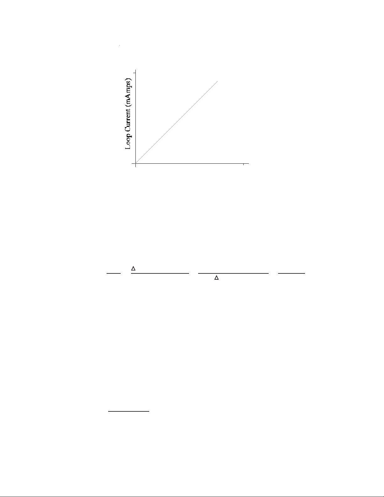
As shown in Figure 4, the transmitter output is linear. Initial Transmitter current output begins at
4mA and increases to a maximum of 20mA. The maximum output of 20mA indicates that the
measuring element has been completely corroded and that the probe must be replaced.
Figure3. Switch Locations andOrientation
21
TUBE
WIRE
SPEC
TEST
R22 R20
FA
+-
4-20mA Loop
Connection
Calibration
Potentiometers
Digital
Circuit Board
Probe Selection
Switch
Switches are UP
Switch is DOWN
*20mAsetting isillustratedin Figure3below.
10
01000
4
20
Probe Start Probe Finish
Probe Units
Figure 4. Output Linearity Relationship
4. Determining the Corrosion Rate
Use the following formula to determine the corrosion rate occurring at the installed probe:
E. Selecting the Probe
To avoid premature probe failure, match the expected probe operating lifetime to the process
system’s expected corrosion rate. This will permit probe replacement during scheduled shut-
downs.
1. Probe Replacement Calculation
A probe replacement calculation is as follows:
T = L x 365
(R)
Corrosion Rate =xx
(mils)
(year) 16 (mA)
Probe Reading (mA) Effective Probe Life (mils)
Time (days) 365 (days)
(year)

11
Where:
L = Effective life in mils.
R = Expected corrosion rate in mils per year.
T = Replacement period in days.
Since the initial estimation of expected corrosion rate prior to monitoring may be in error,
definitely replace probe if transmitter output reaches 20 mA.
F. Maintenance
Once installed, the MS2500E does not require maintenance. However, if malfunctions occur
which cannot be attributed to the data receiving station, power supply, or safety barrier, proceed
as follows:
1. Ensure that the probe is operational and is not completely corroded.
2. Examine all electrical connections for proper electrical connections, signs of corrosion and to
ensure that the connections are environmentally protected.
3. Recalibrate the MS2500E Transmitter following the calibration procedure.
4. ContactMetalSamplesfortechnicalassistanceiftheTransmittercontinuestomalfunctionfollowing
recalibrationoriftheTransmitterisobviously damaged.If advisedto returnthe MS2500Efor repair,
followtheInstructionsforReturningtheInstrumentforRepair.

12
G. Returning the Instrument for Repair
Complete the following procedures to ensure the fastest possible repair and return cycle:
1. If possible, pack the instrument in the original shipping carton. If the original carton is not
available, pack the instrument in a rigid cardboard or wooden carton. Surround the instrument
with a minimum of three inches of resilient packing material such as foam rubber or shredded
newspaper.
2. Ship the instrument prepaid via Air Freight or Air Express to:
MetalSamples
152 Metal Samples Road
Munford, AL 36268
3. Contact Metal Samples by telephone (256) 358-4202orbyfax (256) 358-4515 and inform your
salesrepresentativeof:
a. the name of the airline carrying the instrument
b. the flight number
c. the estimated time of arrival
d. the waybill number and delivery instructions
4. When the instrument is packed, include a copy of the form on the next page, filled in as
required, to expedite the repairs.

13
III. Maintenance and Repair Instructions
Thisformmay bephotocopied forusewhen returninginstruments toMetalSamplesforrepair.
Pleasefillinallknowninformation. Encloseacopyofthefilledinformwiththeinstrument.
1. CHECK ONE:
Repair this instrument under warranty.
Repair this instrument regardless of problem or cost of repair.
Inspect the instrument and advise the customer of the approximate cost of
repairs if the instrument is not covered under warranty. (Note - this
proceduremaydelaythereturn ofthe instrumentto you.)
2. INSTRUMENTIDENTIFICATION:
Instrument Model Number:
Serial Number:
Date of Purchase:
Company’s Purchase Order Number for Original Sale:
3. RETURN THE INSTRUMENT TO:
Company Name:

14
Address:
Telephone Number:
4. INVOICE INSTRUCTIONS:
5. DESCRIPTION OF TROUBLE:
(A clear description of the problem may shorten the repair time.)
6. URGENCYOF REPAIR:
Shipping Address:
MetalSamples
152 Metal Samples Road
Munford, AL 36268

15
IV. Warranty Information
MetalSamples warrants that any part ofthe MS2500E and accessories which provesto be defective
inmaterialor workmanshipwithinone yearofthedateof originalshipmentto Purchaserwillberepaired
orreplaced, at Metal Samples option, free of charge.Thiswarranty does not cover (1) probe assem-
blies,(2) itemsexpendable innature, or (3)items subjectto damagefromnormal wear, misuse or
abuse,orfailure tofollow useand careinstructions.
Alldamaged itemsare to beshipped atPurchaser’s expenseto andfromMetal Sampleswhich shall
havethe rightto finaldetermination astothe existenceand causeof adefect.
Theforegoingshall constitutethe soleand exclusiveremedy ofanypurchaserofMetal Samplesprod-
uctsfor breach of warranty and ISEXCLUSIVEAND IN LIEU OFALLOTHERWARRANTIES,
EXPRESSED,IMPLIED OR STATUTORY,INCLUDING THEIMPLIEDWARRANTIES OR
MERCHANTABILITYAND FITNESS. INNO EVENTSHALLMETALSAMPLESBE LIABLE
FOR SPECIALOR CONSEQUENTIALDAMAGES, OR FORANY DELAYINTHE PERFOR-
MANCE OF THISWARRANTYDUETO CAUSES BEYOND ITS CONTROL.
Orders or request for additional information should be addressed to:
MetalSamples
P.O. Box 8
Munford, AL 36268
Telephone: (256) 358-4202
Fax: (256) 358-4515
The technical information and suggestions contained herein are believed to be reliable, but they
are not to be construed as warranties since conditions of use are beyond our control.
Shipping Address
MetalSamples
152 Metal Samples Road
Munford, AL 36268
Telephone: (256) 358-4202
Fax: (256) 358-4515

Table of contents
Other Metal Samples Transmitter manuals

Metal Samples
Metal Samples MS2901E User manual

Metal Samples
Metal Samples MS2600E User manual

Metal Samples
Metal Samples MS2500L User manual

Metal Samples
Metal Samples CORR Velox MS2800E User manual

Metal Samples
Metal Samples CORR VELOX MS2801E User manual

Metal Samples
Metal Samples MS2701E User manual

Metal Samples
Metal Samples MS2700E User manual

Metal Samples
Metal Samples MS2601E User manual


