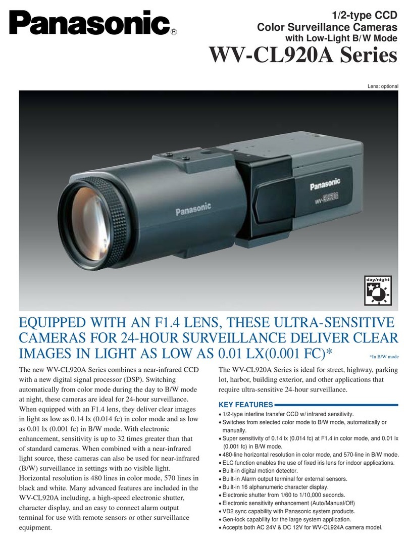
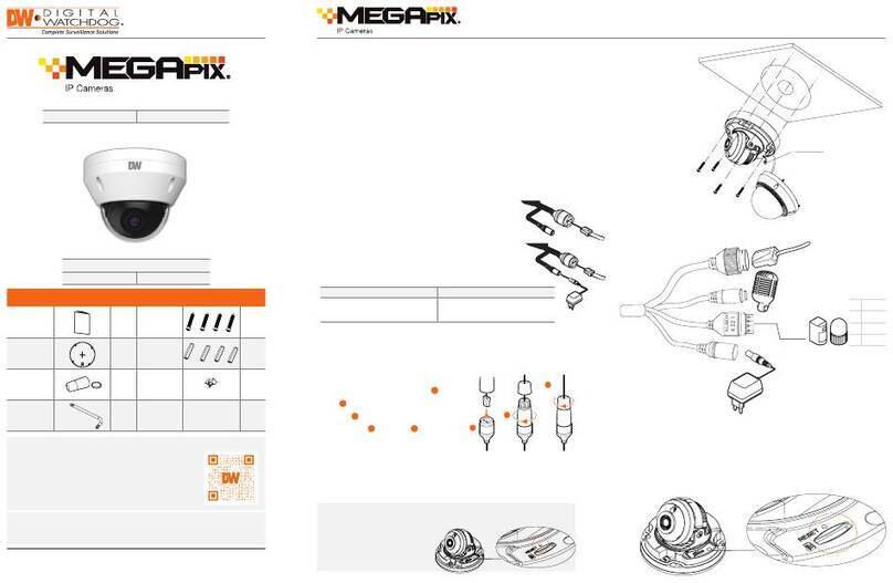
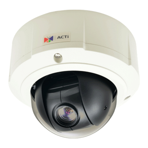
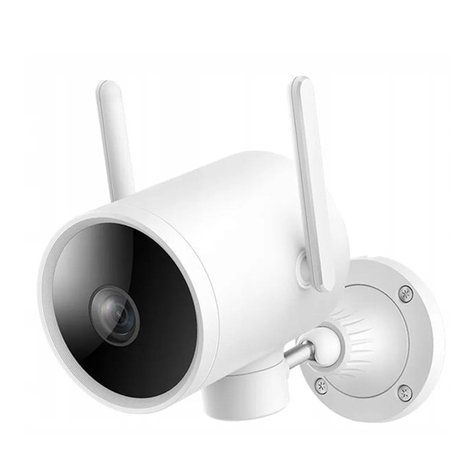
Hi-Tech Solutions C5 Operating instructions

C5
Installation and Operation
Guide
Version 1.2
February, 2010

© Copyright 2009 Hi-Tech Solutions, Inc.

C5 Installation and Operation Guide Table of Contents 1
Table of Contents
About This Guide.................................................................................................................... 5
List of Acronyms.........................................................................................................................5
Safety Symbols ..........................................................................................................................6
Other Symbols............................................................................................................................6
LED Safety Compliance .............................................................................................................6
Related Resources.....................................................................................................................6
Chapter 1. Introduction ........................................................................................................ 7
C5 Overview...............................................................................................................................7
C5 Modes of Operations........................................................................................................7
Typical Installation......................................................................................................................8
Typical Access Control Installation ........................................................................................ 8
Typical Monitoring Mode Installation .....................................................................................8
Sample Installation ................................................................................................................9
Installing Secondary Camera................................................................................................ 9
Installing Dual Camera .........................................................................................................9
Chapter 2. System Components....................................................................................... 11
C5 System Components ..........................................................................................................12
System Software ......................................................................................................................12
Software Integration in a Network........................................................................................12
Host PC....................................................................................................................................13
Chapter 3. Installation and Initial Configuration ............................................................. 15
Physical Installation..................................................................................................................15
Installation Location Considerations .................................................................................... 15
Step 1 – Determining C5 Location.......................................................................................15
Step 2 – Installing C5...........................................................................................................17
Step 3 – Installing a Loop Detector......................................................................................21
Step 4 – Performing Electrical Connections ........................................................................21
Step 5 – Fine Tuning the Loop Detector..............................................................................21
Initial Configuration...................................................................................................................21
Connecting C5 to the Network.............................................................................................21
Initial C5 Setup ....................................................................................................................22
Chapter 4. Using the C5 Portal.......................................................................................... 23
Accessing the C5 Portal ...........................................................................................................24
Logging Off the C5 Portal.........................................................................................................24

2
Chapter 5. C5 Setup ........................................................................................................... 27
Selecting a Camera..................................................................................................................27
Selecting an Illumination Level.................................................................................................28
Setting System Date and Time.................................................................................................29
Editing Motion Detection Settings ............................................................................................30
Restarting C5 ...........................................................................................................................31
Shutting Down C5 ....................................................................................................................31
Chapter 6. Managing the Authorized Cars List ............................................................... 32
Editing the Authorized Cars List ...............................................................................................32
Adding a Car to the Authorized Cars List ............................................................................32
Editing the Details of a Car..................................................................................................33
Removing a Car from the Authorized Cars List ...................................................................34
Viewing the License Plate Recognitions Log ...........................................................................35
Chapter 7. Real Time Monitoring ...................................................................................... 37
Viewing Real Time Images....................................................................................................... 37
Editing the Browser Capture Settings..................................................................................37
Chapter 8. Viewing and Changing the C5 Configuration File........................................ 39
Viewing and Changing General Parameters ............................................................................39
Viewing and Changing Monitoring Parameters ........................................................................40
Viewing and Changing Local Camera Parameters .................................................................. 41
Viewing and Changing Remote Camera Parameters ..............................................................42
Viewing and Changing Network Client Parameters ................................................................. 42
Chapter 9. Changing Network Connection Settings ...................................................... 45
Changing LAN Connection Settings.........................................................................................45
Changing Wireless Connection Settings .................................................................................. 46
Chapter 10. Camera Adjustment....................................................................................... 47
Chapter 11. Acceptance Test ............................................................................................ 49
Chapter 12. Troubleshooting and Support...................................................................... 51
Viewing the Event Log..............................................................................................................51
Contact Information ..................................................................................................................52
Appendix A. Equipment Specifications Data sheets...................................................53
Ground Loops Specifications ...................................................................................................53
Came SMA Datasheet ......................................................................................................... 53
Matrix Ground Loop User guide...........................................................................................53
Appendix B. Enclosure Wiring ......................................................................................60
Appendix C. Sample Bill of Material .............................................................................63
Appendix D. Installation Verification Checklist ...........................................................65

C5 Installation and Operation Guide Table of Contents 3
Appendix E. Software Update .......................................................................................67
Updating C5 Software ..............................................................................................................67
Appendix F. Document History .....................................................................................69


C5 Installation and Operation Guide e About This Guide 5
About This Guide
This guide is intended for Compact Camera-Based Car Controller (C5) installers and
operators, and provides all the information required for installing and operating the C5.
List of Acronyms
Acronym Meaning
BW Black and white
DLL Dynamic Link Library
GUI Graphic User Interface
HTS Hi-Tech Solutions
HW Hardware
ID Identification
IO Input/Output
LED Light Emitting Diodes
LPR License Plate Recognition
MSMQ Microsoft Message Queuing Services
OS Operating system
PC Personal computer
PS Power Supply
SCH SeeCarHead
SDK Software Development Kit
SSH Secure Shell (Port forwarding TCP traffic)
SW Software
TBL Terminal Block
TOS Terminal Operating System

6 Safety Symbols
Safety Symbols
Observe all safety statements to help prevent loss of service, equipment damage,
personal injury, and security problems. This guide uses the following safety symbols:
Important: An Important statement calls attention to information important
to the reader.
WARNING: A warning statement calls attention to a situation that can result
in harm to hardware or equipment.
HAZARD: A hazard statement calls attention to a situation that could cause
personal injury if the hazard is not avoided by following the instructions
provided.
Other Symbols
A Note statement calls your attention to additional information.
LED Safety Compliance
The C5 illumination unit complies with International Standard IEC 60825-1, for Class 1
LED (light emitting diodes) products containing Class 1 LED’s. This Class 1 LED product
poses no hazard to the user or to any other person present near the illumination unit. Use
of the illumination unit is totally safe and needs no specific precautions.
WARNING: Do not look directly into the camera for more than a few
seconds.
Related Resources
For more information on C5 and related systems, see the following guides. You can
download them from http://www.htsol.com.
♦SeeData – Provides interfacing information.
♦SeeLane – Describes a PC-based solution similar to C5.

C5 Installation and Operation Guide Introduction 7
Chapter 1
Introduction
This chapter provides an overview of C5, its modes of operation, and how it is typically
used.
C5 Overview
C5 is all in one highly integrated unit, containing a computer, one or two cameras camera,
and illumination, which performs all the functions of a License Plate Recognition (LPR)
system with its embedded microprocessor and HTS SeeCar recognition package. C5 is a
versatile stand-alone unit that can be used either for access control in parking installations
or as a license plate sensor to report license plate numbers.
C5 identifies the license plate number, compares it with the vehicle database, and can
automatically open a gate for authorized vehicles. The system can also be used in traffic
surveillance and monitoring applications to track passing vehicles and automatically
generate a vehicle list.
For applications involving multiple LPR points, several individual C5 units can be
networked together to a single server. Authorized vehicle numbers are stored in the unit’s
database, and pre-registered users can access and modify it via the internal web server
interface, using a network (LAN) or Internet connection. C5 can transmit the recognized
plate number to other systems via TCP/IP over the LAN or using a wireless connection.
The unit is triggered either by its internal software trigger based on motion detection, or by
an external trigger such as a loop detector.
Note that a basic configuration is without VMD. Customers who interested in full
system (with VMD) should contact HTS for upgrade system to full version.
C5 Modes of Operations
C5
can operate in either of the following modes:
♦Access Control Mode – The unit opens a gate for an authorized vehicle listed in its
local database. It can also optionally send the result via the network to SeeData.
♦Monitoring Mode – The unit reports the recognized license plate numbers via the
network using SeeData.
The operation mode is specified using a configuration parameter. It is pre-configured at
the factory according to the order, but can be changed using the C5 internal web portal.

8 Typical Installation
Typical Installation
C5 is typically installed at the entrance to a secured area or parking lot, requiring only a
power supply and, optionally, a gate.
Typical Access Control Installation
The following figure illustrates how the system is typically installed at the entrance to a
secured area. A sensor, such as the internal motion detector or a hardware loop detector,
indicates the presence of a vehicle. The sensor signals the C5 unit, located behind the
gate’s boom, to start a new recognition sequence. C5 identifies the vehicle’s license plate
number, and if is authorized, C5 opens the gate.
Figure 1: Typical Access-control Installation
For most secured areas, the system can control only the entrance. The exit is
automatically opened for the vehicles exiting the secured area via a direct connection
from the sensor to the gate.
Typical Monitoring Mode Installation
In a monitoring mode installation, C5 is used to report on passing vehicles.
In this mode, the unit can be connected to other units via a local network (intranet) that
reports the recognition results, including the captured image, to a central server. The data
is transmitted via TCP/IP over a wired or wireless connection.

C5 Installation and Operation Guide Equipment Specifications Data sheets 9
Sample Installation
The following photo shows a sample access control installation in a secured office area.
This unit operates with an internal software trigger (motion detection) and opens the
barrier for vehicles that match its “white list”. It sends the recognition results via TCP/IP
over a wired or wireless connection.
Figure 2: Sample C5 Installation
Installing Secondary Camera
Secondary camera is an optional ad on camera for improving recognition coverage. In
Stereo mode, the main idea is using two different points of view for recognition. Additional
to the primary C5 camera installation, a secondary camera (SCH-3 camera) is installed in
order to improve recognition rates.
Installing Dual Camera
In dual mode, dual cameras – a primary camera and a secondary camera are installed
side by side in the same enclosure. The secondary camera can be use for one of the two
reasons:
i. Provide a second point of view for improving field of view and recognition coverage.
ii. Presents overview image.
Consult marketing and sales for ordering information


C5 Installation and Operation Guide System Components 11
Chapter 2
System Components
The C5 system architecture is illustrated in the following diagram. The inputs are a DC
adapter connected to the mains, and an optional dry-contact sensor indicating vehicle
presence, such as a loop detector. You can optionally use the unit’s internal motion
detection instead of an external trigger.
The optional output is the gate relay open signal, which can be used to open the gate for
authorized vehicles.
Figure 3: Block Diagram of C5 System

12 C5 System Components
C5 System Components
The C5 system contains the following main components:
♦C5 unit.
♦Power supply – 15 VDC, 50W, 110-220VAC power supply.
♦External vehicle detector – Optional. A standard dry-contact sensor, such as a loop
detector. You can optionally use the C5 internal motion detector.
♦Gate control – Optional. Controlled by the C5 output relay. The gate is opened for an
authorized vehicle only. This component is required only in an access control
installation.
System Software
C5 is shipped with pre-installed software components. The main pre-installed software
components include:
♦C5 – Main application.
♦cars.txt – Authorized cars database file. You can update the list of authorized cars, as
described in Editing the Authorized Cars List.
♦Format.ini – Country-specific license plates recognition information.
♦C5.config – C5 configuration settings. You can edit the settings of the C5
configuration file, as described in Viewing and Changing the C5 Configuration File.
C5 is an FTP server and can work with any FTP client, such as WinSCP. C5 is also an
SSH server and can work with any SSH client, such as PuTTY.
Software Integration in a Network
C5 can either operate as a standalone unit, or can connect to a central server using
“SeeData”, an HTS utility that is used for network connectivity.
SeeData can be installed on a central server. Each C5 unit can interface with SeeData.
When the unit is connected to a central server, the recognition result, including the image,
is sent over the network as a TCP/IP packet. It is intercepted by SeeData and converted
to a MSMQ message, which is supported by other HTS recognition systems, such as
SeeLane.
Each message contains:
♦Recognition string.
♦Date and time.
♦Lane number – a unique ID for the lane, given by the user.
♦Authorization information.
♦Authorized Yes /No.
♦Driver name if available.
♦Optional image file path.

C5 Installation and Operation Guide Equipment Specifications Data sheets 13
Source code for sample client applications is available in VC++ and C# and can be
downloaded from the HTS support website. To test your client, refer to SeeData Interface
control document.
Host PC
The PC host is used for ongoing operations, such as updating the authorized cars list or
receiving results, and for installation and maintenance. Use any standard PC or laptop,
loaded with the necessary applications, connected via network communications.


C5 Installation and Operation Guide Installation and Initial Configuration 15
Chapter 3
Installation and Initial Configuration
Physical Installation
This section describes the physical installation of a single lane C5 system.
Installation Location Considerations
You can install C5 so that it will capture an image of either the front or rear of a vehicle.
The probable reasons for a rear installation include:
♦Front installation is not possible due to traffic lane limitations. For example, the front
area is located in a public area in which no installation is permitted.
♦Vehicles carry only rear license plates. This is true for most of the United States.
♦Additional installation of a secondary camera in order to increase the recognition
coverage. In this case, two cameras are installed per lane. One is a C5, designated
the primary. The second camera has no internal CPU and is designated the
secondary. Typically, the secondary camera is the SCH3-IR for reflective plates and
the SCH3-Yellow for non reflective plates.
The dual-camera option (primary and secondary in dual enclosure) is not currently
supported.
Step 1 – Determining C5 Location
The location of C5 depends on whether you are installing it to capture an image of the
front of a vehicle or its rear.
Determining Front Installation Distances
♦Install C5 2.5 meters from the barrier, in the direction of traffic, at the side of the lane
as near as possible to the lane. For non-reflective plates and USA size plates, install
C5 2 meters from the barrier (Bin Figure 4).
♦The distance from C5 to the license plate of the car should be 7.5 meters for a plate
length of 50 cm, or 6.5 meters for a plate length of 30 cm (Ain Figure 4).
WARNING: A possible problem is that the barrier blocks the effective recognition
view zone, which is the area from the start of detection. In most gates, the
barrier’s height is 0.80 to 1.20 meters, so no blocking occurs. However, this
should be tested and avoided if necessary.

16 Physical Installation
♦Try to install C5 as close as possible to the traffic lane, within 0.4 to 0.5 meters (Cin
Figure 4). Do not install C5 so close that it can get damaged. You can install C5 on
either side of the traffic lane.
Figure 4: Front Installation Distances
If motion detection is used instead of a loop detector, the loop area in the
illustration indicates the desired area of detection.

C5 Installation and Operation Guide Equipment Specifications Data sheets 17
Determining Rear Installation Distances
♦Install C5 4 meters from the loop detection line (Bin Figure 5). This translates to about
9 meters or more from the front of the car since a typical vehicle is about 4 meters
long.
♦Try to install C5 as close as possible to the traffic lane, within 0.0 to 0.5 meters (Cin
Figure 5).
Figure 5: Rear Installation Distances
Step 2 – Installing C5
The recommended angle between C5 and the car is 15-16 degrees. The angle should not
exceed 30 degrees.
The camera should face downwards in order to minimize the sun effect. Since most plates
are mounted at a height of 0.20 to 1.25 meters, the recommended height for the C5 unit is
between 1 to 1.2 meters.
The maximum height at which the C5 should be installed is 3 meters. In this case, the
camera should be positioned such that the center of the vertical field of view is the trigger
area. For higher installations, consult Hi-Tech Solutions.

18 Physical Installation
You can mount the C5 unit on a wall, or install it on a pole or tripod. The following sections
provide installation instructions.
Mounting C5 on a Wall
Follow the instructions as indicated in the following illustrations:
Figure 6: Mounting C5 on a Wall
Table of contents
