Hi-Way New Leader L5034G4 User manual

MODEL L5034G4
UNIT SERIAL NUMBER _______________________
MANUAL NUMBER: 305438-G
EFFECTIVE 03/2016
1330 76TH AVE SW
CEDAR RAPIDS, IA 52404-7052
PHONE (319) 363-8281 | FAX (319) 286-3350
www.highwayequipment.com
Copyright 2003 Highway Equipment Company, Inc.

2
Please Give Part No., Description
& Unit Serial No.
L5034G4NEW LEADER
TABLE OF CONTENTS CONTINUED
305438-G
Page Rev. A
305438-G
Page Rev. A
TABLE OF CONTENTS
Table of Contents������������������������������������������������������������������������������������������������������������������������������������������ 2
Warranty������������������������������������������������������������������������������������������������������������������������������������������������������� 4
Preface���������������������������������������������������������������������������������������������������������������������������������������������������������� 5
Safety������������������������������������������������������������������������������������������������������������������������������������������������������������ 6
Safety Decals ������������������������������������������������������������������������������������������������������������������������������������������������ 8
General Safety Rules-Operaons���������������������������������������������������������������������������������������������������������������� 10
general descripon������������������������������������������������������������������������������������������������������������������������������������� 15
Dimensions & Capacies ���������������������������������������������������������������������������������������������������������������������������� 16
Inial Start-up��������������������������������������������������������������������������������������������������������������������������������������������� 17
Field Tesng������������������������������������������������������������������������������������������������������������������������������������������������ 18
General Operang Procedures������������������������������������������������������������������������������������������������������������������� 19
Lubricaon & Maintenance������������������������������������������������������������������������������������������������������������������������ 20
Preventave Maintenance Pays! ������������������������������������������������������������������������������������������������������ 20
Hydraulic System������������������������������������������������������������������������������������������������������������������������������� 20
Service Schedule������������������������������������������������������������������������������������������������������������������������������� 20
Hydraulic Hose������������������������������������������������������������������������������������������������������������������������ 21
Conveyor Chain����������������������������������������������������������������������������������������������������������������������� 22
Conveyor Gearcase����������������������������������������������������������������������������������������������������������������� 23
Lubricaon of Bearings����������������������������������������������������������������������������������������������������������� 23
Fasteners �������������������������������������������������������������������������������������������������������������������������������� 23
Clean Up ��������������������������������������������������������������������������������������������������������������������������������� 23
Lubricant and Hydraulic Oil Specicaons ������������������������������������������������������������������������������������������������� 24
Hydraulic System������������������������������������������������������������������������������������������������������������������������������� 24
Gearcase Lubricant ��������������������������������������������������������������������������������������������������������������������������� 24
Grease Gun Lubricant ����������������������������������������������������������������������������������������������������������������������� 24
Chain Oiler Mixture��������������������������������������������������������������������������������������������������������������������������� 24
Lubricaon and Maintenance chart ����������������������������������������������������������������������������������������������������������� 25
Conveyor Selecon������������������������������������������������������������������������������������������������������������������������������������� 26
Troubleshoong ����������������������������������������������������������������������������������������������������������������������������������������� 27
Standard Torques ��������������������������������������������������������������������������������������������������������������������������������������� 30
Instrucons for Ordering parts������������������������������������������������������������������������������������������������������������������� 31
TABLE OF CONTENTS

3
Please Give Part No., Description
& Unit Serial No.
L5034G4NEW LEADER
TABLE OF CONTENTS CONTINUED
305438-G
Page Rev. A
305438-G
Page Rev. A
Spreader Parts List���������������������������������������������������������������������������������������������������������������������������������������� 32
Mounng Angle ��������������������������������������������������������������������������������������������������������������������������������� 32
Mud Flaps ������������������������������������������������������������������������������������������������������������������������������������������� 33
Feedgate ��������������������������������������������������������������������������������������������������������������������������������������������� 34
Pintle Chain COnveyor (#1) ���������������������������������������������������������������������������������������������������������������� 36
Pintle CHain COnveyor (#2 & #3) ������������������������������������������������������������������������������������������������������� 37
Chain Shields��������������������������������������������������������������������������������������������������������������������������������������� 38
Conveyor Idler������������������������������������������������������������������������������������������������������������������������������������� 39
Conveyor Drive ����������������������������������������������������������������������������������������������������������������������������������� 40
Encoder ���������������������������������������������������������������������������������������������������������������������������������������������� 41
Conveyor Chain Oiler �������������������������������������������������������������������������������������������������������������������������� 42
Front Wiper����������������������������������������������������������������������������������������������������������������������������������������� 45
Rear Wiper Groups ����������������������������������������������������������������������������������������������������������������������������� 46
Fenders - Full Floataon Tires ������������������������������������������������������������������������������������������������������������ 48
Spinner Divider, Guard & Shields �������������������������������������������������������������������������������������������������������� 50
Spinner Sensor������������������������������������������������������������������������������������������������������������������������������������ 51
Spinner Assembly ������������������������������������������������������������������������������������������������������������������������������� 52
Bin Sensor ������������������������������������������������������������������������������������������������������������������������������������������� 55
Hydraulic Reservoir����������������������������������������������������������������������������������������������������������������������������� 56
Hydraulic Reservoir & Cooler�������������������������������������������������������������������������������������������������������������� 58
Hydraulics ������������������������������������������������������������������������������������������������������������������������������������������� 60
Spinner Control Valve - Style A ����������������������������������������������������������������������������������������������������������� 64
Spinner Control Valve - Style B������������������������������������������������������������������������������������������������������������ 65
PWM Spinner Control Valve Controller����������������������������������������������������������������������������������������������� 66
Spinner Control Valve - Manual ���������������������������������������������������������������������������������������������������������� 67
Pump Hydraulics ��������������������������������������������������������������������������������������������������������������������������������� 68
Pump Hydraulics Connued���������������������������������������������������������������������������������������������������������������� 69
Relief Valve Groups����������������������������������������������������������������������������������������������������������������������������� 70
Pressure Gauge Kit������������������������������������������������������������������������������������������������������������������������������ 71
Spinner Motor������������������������������������������������������������������������������������������������������������������������������������� 72
Gearcase & Breather Tube Kit������������������������������������������������������������������������������������������������������������� 74
Gearcase - Single Pinion���������������������������������������������������������������������������������������������������������������������� 75
Decals�������������������������������������������������������������������������������������������������������������������������������������������������� 76
Sight Window�������������������������������������������������������������������������������������������������������������������������������������� 78
TABLE OF CONTENTS

Insert Current New Leader
Warranty
WARRANTY

5
L5034G4NEW LEADER
HEADER
305438-G
Page Rev. A
Please Give Part No., Description
& Unit Serial No.
HEADER
PREFACE
PLEASE ! ALWAYS THINK SAFETY FIRST !!
The purpose of this manual is to familiarize the person (or persons) using this unit with the informaon necessary
to properly install, operate, and maintain this system. The safety instrucons indicated by the safety alert symbol
in the following pages supersede the general safety rules. These instrucons cannot replace the following: the
fundamental knowledge that must be possessed by the installer or operator, the knowledge of a qualied person,
or the clear thinking necessary to install and operate this equipment� Since the life of any machine depends largely
upon the care it is given, we suggest that this manual be read thoroughly and referred to frequently� If for any
reason you do not understand the instrucons, please call your authorized dealer or our Product Sales and Support
Department at 1-888-363-8006�
It has been our experience that by following these installaon instrucons, and by observing the operaon of
the spreader, you will have sucient understanding of the machine enabling you to troubleshoot and correct all
normal problems that you may encounter. Again, we urge you to call your authorized dealer or our Product Sales
and Support Department if you nd the unit is not operang properly, or if you are having trouble with repairs,
installaon, or removal of this unit.
We urge you to protect your investment by using genuine HECO parts and our authorized dealers for all work other
than roune care and adjustments.
Highway Equipment Company reserves the right to make alteraons or modicaons to this equipment at any me.
The manufacturer shall not be obligated to make such changes to machines already in the eld.
This Safety Secon should be read thoroughly and referred to frequently.
ACCIDENTS HURT !!!
ACCIDENTS COST !!!
ACCIDENTS CAN BE AVOIDED !!!
SAFETYPREFACE

6
L5034G4
NEW LEADER
HEADER
305438-G
Page Rev. A
Please Give Part No., Description
& Unit Serial No.
HEADER
SAFETY
TAKE NOTE! THIS SAFETY ALERT SYMBOL FOUND THROUGHOUT THIS MANUAL IS USED TO
CALL YOUR ATTENTION TO INSTRUCTIONS INVOLVING YOUR PERSONAL SAFETY AND THAT
OF OTHERS. FAILURE TO FOLLOW THESE INSTRUCTIONS CAN RESULT IN INJURY OR DEATH.
In this manual and on the safety signs placed on the unit, the words “DANGER,” “WARNING,” “CAUTION,” and
“NOTICE” are used to indicate the following:
Indicates an imminently hazardous situaon that, if not avoided, WILL
result in death or serious injury. This signal word is to be limited to the
most extreme situaons and typically for machine components that, for
funconal purposes, cannot be guarded.
DANGER
Indicates a potenally hazardous situaon that, if not avoided, COULD result
in death or serious injury, and includes hazards that are exposed when
guards are removed. It may also be used to alert against unsafe pracces.
WARNING
Indicates a potenally hazardous situaon that, if not avoided, MAY result
in minor or moderate injury. It may also be used to alert against unsafe
pracces.
CAUTION
NOTICE!
Is used for informaonal purposes in areas which may involve damage or
deterioraon to equipment but generally would not involve the potenal
for personal injury.
NOTE: Provides addional informaon to simplify a procedure or clarify a process.
The need for safety cannot be stressed strongly enough in this manual. At Highway Equipment Company, we
urge you to make safety your top priority when operang any equipment. We rmly advise that anyone allowed
to operate this machine be thoroughly trained and tested, to prove they understand the fundamentals of safe
operaon.
The following guidelines are intended to cover general usage and to assist you in avoiding accidents� There will
be mes when you will run into situaons that are not covered in this secon. At those mes the best standard to
use is common sense. If, at any me, you have a queson concerning these guidelines, please call your authorized
dealer or our Product Sales & Support Department at (888) 363-8006�
SAFETY

7
L5034G4NEW LEADER
HEADER
305438-G
Page Rev. A
Please Give Part No., Description
& Unit Serial No.
HEADER
SAFETY CONTINUED
SAFETY DECAL MAINTENANCE INSTRUCTIONS
1� Keep safety decals and signs clean and legible at all mes.
2� Replace safety decals and signs that are missing or have become illegible�
3� Replaced parts that displayed a safety sign should also display the current sign�
4� Safety decals or signs are available from your dealer’s Parts Department or our Cedar Rapids factory�
SAFETY DECAL INSTALLATION INSTRUCTIONS
1� Clean Surface
Wash the installaon surface with a synthec, free-rinsing detergent. Avoid washing the surface with a soap
containing creams or loon. Allow to dry.
2� Posion Safety Decal
Decide on the exact posion before applicaon. Applicaon marks may be made on the top or side edge of
the substrate with a lead pencil, marking pen, or small pieces of masking tape. NOTE: Do not use chalk line,
china marker, or grease pencil� Safety decals will not adhere to these�
3� Remove the Liner
A small bend at the corner or edge will cause the liner to separate from the decal. Pull the liner away in a
connuous moon at a 180-degree angle. If the liner is scored, bend at score and remove.
4� Apply Safety Decal
a� Tack decal in place with thumb pressure in upper corners�
b� Using rm inial squeegee pressure, begin at the center of the decal and work outward in all direcons
with overlapping strokes. NOTE: Keep squeegee blade even—nicked edges will leave applicaon bubbles.
c� Pull up tack points before squeegeeing over them to avoid wrinkles�
5� Remove Pre-mask
If safety decal has a pre-mask cover remove it at this me by pulling it away from the decal at a 180 degree
angle. NOTE: It is important that the pre-mask covering is removed before the decal is exposed to sunlight to
avoid the pre-mask from permanently adhering to the decal�
6� Remove Air Pockets
Inspect the decal in the at areas for bubbles. To eliminate the bubbles, puncture the decal at one end
of the bubble with a pin (never a razor blade) and press out entrapped air with thumb moving toward the
puncture�
7� Re-Squeegee All Edges.
SAFETY

8
L5034G4
NEW LEADER
HEADER
305438-G
Page Rev. A
Please Give Part No., Description
& Unit Serial No.
HEADER
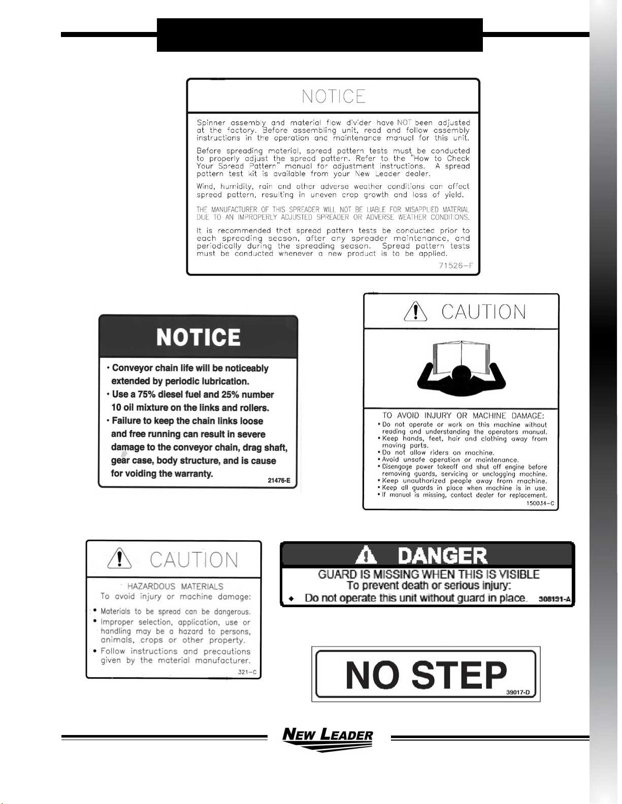
SAFETY DECALS
SAFETY
9
L5034G4NEW LEADER
HEADER
305438-G
Page Rev. A
Please Give Part No., Description
& Unit Serial No.
HEADER
SAFETY DECALS CONTINUED
SAFETY

10
L5034G4
NEW LEADER
HEADER
305438-G
Page Rev. A
Please Give Part No., Description
& Unit Serial No.
GENERAL SAFETY RULES-OPERATIONS
1� Before aempng
to operate this unit,
read and be sure
you understand
the operaon
and maintenance
manual� Locate
all controls and
determine the use
of each� Know
what you are doing!
2� When leaving the unit unaended for any reason,
be sure to:
a� Take power take-o out of gear.
b� Shut o conveyor and spinner drives.
c� Shut o vehicle engine and unit engine (if so
equipped)�
d� Place transmission of the vehicle in “neutral”
or “park”.
e� Set parking brake rmly.
f� Lock ignion and take keys with you.
g� Lock vehicle cab�
h� If on steep grade, block wheels�
These acons are recommended to avoid
unauthorized use, runaway, vandalism, the and
unexpected operaon during start-up.
3� Do not read, eat, talk on a mobile phone or take
your aenon away while operang the unit.
Operang is a full-me job.
4� Stay out of the
spreader� If it’s
necessary to enter
the spreader,
return to the shop,
empty body, turn
o all power, set
vehicle brakes,
lock engine
starng switch and
remove keys before
entering. Tag all controls to prohibit operaon.
Tags should be placed, and later removed, only by
person working in the body�
5� Guards and covers are provided to help avoid
injury. Stop all machinery before removing them.
Replace guards and covers before starng spreader
operaon.
6� Stay clear of any moving
members, such as
shas, couplings and
universal joints. Make
adjustments in small
steps, shung down
all moons for each
adjustment.
7� Before starng unit, be sure everyone is clear and
out of the way�
8� Do not climb
on unit� Use
the inspecon
ladder or a
portable ladder
to view the unit�
Be careful in
geng on and
o the ladder,
especially in
wet, icy, snowy
or muddy
conditions�
Clean mud, snow or
ice from steps and
footwear�
9� Do not allow anyone to ride on any part of unit for
any reason�
10� Keep away from
spinners while they are
turning:
a� Serious injury
can occur if
spinners touch
you�
b� Rocks, scrap metal or other material can be
thrown o the spinner violently. Stay out of
discharge area�
c� Make sure discharge area is clear before
spreading�
SAFETY

11
L5034G4NEW LEADER
HEADER
305438-G
Page Rev. A
Please Give Part No., Description
& Unit Serial No.
GENERAL SAFETY RULES-OPERATIONS CONTINUED
11� Inspect spinner ns, spinner frame mounng and
spinner n nuts and screws every day. Look for
missing fasteners, looseness, wear and cracks�
Replace immediately if required� Use only new
SAE grade 5 or grade 8 screws and new self-
locking nuts�
12� Inspect all bolts, screws,
fasteners, keys, chain
drives, body mounngs
and other aachments
periodically� Replace
any missing or damaged
parts with proper
specicaon items.
Tighten all bolts, nuts and screws to
specied torques according to the
torque chart in this manual�
13� Shut o engine
before lling fuel
and oil tanks� Do
not allow overow.
Wipe up all spills�
Do not smoke� Stay
away from open
ame. FIRE HAZARD!
14� Starng uids
and sprays
are extremely
flammable�
Don’t smoke�
Stay away from
ame or heat!
15� All vehicles should
be equipped with a serviceable re exnguisher
of 5 BC rang or larger.
16� Hydraulic system and
oil can get hot enough
to cause burns� DO
NOT work on system
that is hot. Wait unl
oil has cooled� If an
accident occurs, seek
immediate medical
assistance�
17� Wear eye protecon while working around or on
unit�
18� Read, understand and follow instrucons and
precauons given by the manufacturer or supplier
of materials to be spread. Improper selecon,
applicaon, use or handling may be hazardous to
people, animals, plants, crops or other property�
CAUTION
If spreader is used to
transport chemicals, check
with your chemical supplier
regarding DOT (Department of
Transportaon) requirements.
19� Cover all loads that can spill or blow away� Do
not spread dusty
materials where dust
may create polluon
or a trac visibility
problem�
20� Turn slowly and
be careful when
traveling on rough
surfaces and side
slopes, especially with a loaded spreader� Load
may shi causing unit to p.
21� Read and understand the precauonary decals on
the spreader� Replace any that become defaced,
damaged, lost or painted over� Replacement
decals can be ordered from your dealer’s parts
department or from Highway Equipment Company
by calling (319) 363-8281�
SAFETY

12
L5034G4
NEW LEADER
HEADER
305438-G
Page Rev. A
Please Give Part No., Description
& Unit Serial No.
7� Some parts and
assemblies are
quite heavy. Before
aempng to
unfasten any heavy
part or assembly,
arrange to support it
by means of a hoist,
by blocking or by
use of an adequate
arrangement to prevent it from falling, pping,
swinging or moving in any manner which may
damage it or injure someone. Always use liing
device that is properly rated to li the equipment.
Do not li loaded spreader. NEVER LIFT EQUIPMENT
OVER PEOPLE�
8� If repairs require use
of a torch or electric
welder, be sure that
all ammable and
combusble materials
are removed� Fuel
or oil reservoirs must
be emped, steam
cleaned and lled
with water before
aempng to cut or weld them. DO NOT weld or
ame cut on any tank containing oil, gasoline or
their fumes or other ammable material, or any
container whose contents or previous contents are
unknown�
9� Keep a fully charged re exnguisher readily
available at all mes. It should be a Type ABC or a
Type BC unit.
10� Cleaning solvents should be used with care�
Petroleum based solvents are ammable and
present a re hazard. Don’t use gasoline. All
solvents must be used with adequate venlaon,
as their vapors should not be inhaled�
GENERAL SAFETY RULES-MAINTENANCE
1� Maintenance includes all
lubricaon, inspecon,
adjustments (other
than operaonal control
adjustments such as
feedgate openings,
conveyor speed, etc�)
part replacement, repairs
and such upkeep tasks as
cleaning and painng.
2� When performing any
maintenance work, wear proper protecve
equipment—always wear eye protecon—safety
shoes can help save your toes—gloves will help
protect your hands against cuts, bruises, abrasions
and from minor burns—a hard hat is beer than a
sore head!
3� Use proper tools for the job
required� Use of improper
tools (such as a screwdriver
instead of a pry bar, a
pair of pliers instead of a
wrench, a wrench instead
of a hammer) not only can
damage the equipment being worked on, but can
lead to serious injuries. USE THE PROPER TOOLS.
4� Before aempng any maintenance work
(including lubricaon), shut o power completely.
DO NOT WORK ON RUNNING MACHINERY!
5� When guards and covers are removed for any
maintenance, be sure that such guards are
reinstalled before unit is put back into operaon.
6� Check all screws, bolts and nuts for proper torques
before placing equipment back in service� Refer to
torque chart in this manual�
SAFETY

13
L5034G4NEW LEADER
HEADER
305438-G
Page Rev. A
Please Give Part No., Description
& Unit Serial No.
GENERAL SAFETY RULES-MAINTENANCE CONTINUED
11� When baeries are
being charged or
discharged, they
generate hydrogen
and oxygen gases. This
combinaon of gases
is highly explosive. DO
NOT SMOKE around
baeries—STAY AWAY
FROM FLAME—don’t
check baeries by shorng terminals as the spark
could cause an explosion. Connect and disconnect
baery charger leads only when charger is “o”.
Be very careful with “jumper” cables.
12� Baeries contain strong sulfuric acid—handle
with care. If acid gets on you, ush it o with
large amounts of water� If it gets in your eyes,
ush it out with plenty of water immediately and
get medical help�
13� Hydraulic uid under
high pressure leaking
from a pin hole are
dangerous as they can
penetrate the skin as
though injected with
a hypodermic needle�
Such liquids have a
poisonous eect and
can cause serious
wounds� To avoid hazard, relieve pressure before
disconnecng hydraulic lines or performing work
on system. Any uid injected into the skin must
be treated within a few hours as gangrene may
result� Get medical assistance immediately if
such a wound occurs� To check for such leaks,
use a piece of cardboard or wood instead of your
hand. Make sure all hydraulic uid connecons
are ght and all hydraulic hoses and lines are
in good condion before applying pressure to
system. Wear protecve gloves and safety glasses
or goggles when working with hydraulic systems�
14� The ne spray from a small hydraulic oil leak can
be highly explosive—DO NOT SMOKE—STAY
AWAY FROM FLAME OR SPARKS.
SAFETY

14
L5034G4
NEW LEADER
HEADER
305438-G
Page Rev. A
Please Give Part No., Description
& Unit Serial No.
1� The selecon of the vehicle on which a spreader
body is to be mounted has important safety
aspects. To avoid overloading:
a� Do not mount spreader on a chassis which,
when fully loaded with material to be
spread, will exceed either the Gross Axle
Weight Rang (GAWR) or the Gross Vehicle
Weight Rang (GVWR) for the chassis.
b� Do install the spreader only on a vehicle
with cab-to-axle dimension recommended
for the spreader body length shown�
2� Follow mounng instrucons in the Installaon
secon of this manual. If mounng condions
require deviaon from these instrucons refer to
factory�
3� When making the installaon, be sure that the
lighng meets Federal Motor Vehicle Safety
Standard (FMVSS) No. 108, ASABE S279 and all
applicable local and state regulaons.
4� When selecng a PTO to drive hydraulic pump, do
not use a higher percent speed drive than indicated
in the Installaon secon of this manual. Too high
a percent PTO will drive pump at excessive speed,
which can ruin the pump, but more importantly,
will overheat the hydraulic oil system and increase
the possibility of re.
5� When
truck frame must
be shortened, cut
o only the poron
that extends behind
rear shackle in
accordance with the
truck manufacturer’s
recommendaons. If
a torch is used to make
the cut, all necessary precauons should be taken
to prevent re. Cuts should not be made near
fuel tanks and hydraulic oil reservoirs, fuel, brake,
electric or hydraulic lines and such lines should
be protected from ame, sparks or molten metal.
Tires should be removed if there is any chance
of their being struck by ame, sparks or molten
metal. Have a re exnguisher handy.
GENERAL SAFETY RULES-INSTALLATION
6� Do not
weld on
vehicle
frame
as such
welding
can lead
to fague
cracking
and must be avoided� When drilling holes in frame
member, drill only through the vercal web porons
do not put holes in top or boom anges. Refer to
truck manufacturer’s recommendaons.
7� Be sure that welds between mounng bars and sill or
between mounng angles and spreader cross sills are
sound, full llet welds. Center mounng angles so
that good llet welds can be made on three sides—
and edge bead weld is not a sasfactory weld for this
service� Use 309 rod/wire for carbon steel and 409
steel. On 304 stainless steel bodies use SAE grade 5
bolts—welding is recommended if type 308 welding
rod is available�
8� Install
controls so that they are located of convenient use�
Posion them so that they do not interfere with any
vehicle control and that they do not interfere with
driver or passenger or with access to or exit from the
vehicle�
9� Check for vehicle visibility, especially toward the rear�
Reposion or add mirrors so that adequate rearward
visibility is maintained�
10� Add Cauon, Warning, Danger and Instrucon decals
as required. Peel o any label masking which has not
been removed�
11� Install all guards as required�
12� Check installaon completely to be sure all fasteners
are secure and that nothing has been le undone.
SAFETY

NEW LEADER
15
HEADER L5034G4
Please Give Part No., Description
& Unit Serial No.
305438-G
Page Rev. A
GENERAL DESCRIPTION
The Model L5034G4 is a hopper type spreader intended for spreading feedlot manure, waste water sludge, industrial
waste, paper mill waste, compost, marl, poultry lier and y ash. It is intended for truck chassis or otaon vehicle
mounng.
The unit is powered hydraulically and provides independent variable speed control for the spinner and full automac
ground speed control for the conveyor by means of a motorized valve with sha sensor. Tandem gear type hydraulic
pumps provide the power and are driven by means of a transmission PTO�
The 34” wide (86 cm) conveyor runs the full length of the hopper boom to deliver material to the spinners through
a hydraulically adjustable metering gate at the rear of the hopper body. A feedgate sight gauge allows monitoring of
the feedgate opening from the cab� The conveyor is driven by two orbital type hydraulic motors mounted to 6-to-1
rao spur gear cases. Three conveyor opons are available: pintle type chain joined by cross bars every third link
(#1), every other link (#2), or every link (#3)
The distributor spinner assembly has two 30” (76cm) diameter discs. Each disc has the opon of four or six formed
and heat treated ns that are adjustable to radial angle. The spinner is fully adjustable by means of a rotang
handle�
This product is intended for commercial use only�
OPERATION & MAINT.
GENERAL DESCRIPTION

16
L5034G4
NEW LEADER HEADER
Please Give Part No., Description
& Unit Serial No.
305438-G
Page Rev. A
DIMENSIONS & CAPACITIES
70.7
(179.6 cm)
A
B
4.00
(10 cm)
MIN
CA/CT*
C*
118.3 (300cm)
(OUTSIDE)
128 (325 cm)
(FENDER WIDTH)
Unit Length Overall Lenth
A
Body Length
B
Frame Length
C
Cab to Axle or Cab to Tandem
CA/CT
13’ 196” (498 cm) 144” (366 cm) 147” (373 cm) 108” (274cm) CA
14’ 208” (528 cm) 156” (396 cm) 159” (404 cm) 114” (290cm) CA
16’ 232” (589 cm) 180” (457 cm) 183” (465 cm) 138” (351cm) CA/
120” (305cm) CT
18’ 256” (650 cm) 204” (518 cm) 207” (526 cm) 153” (389cm) CA/
144” (366cm) CT
21’ 292” (742 cm) 240” (610 cm) 243”(617 cm) 188” (478cm) CA/
162” (411cm) CT
Unit Length Struck Capacity
Cu Yd (Cu M) Cu Ft
Spreader Weight
Approx. Pounds (kilograms)As Shipped
13’ (3�96 m) 13�4 (10�2) 361 5200 (2359)
14’ (4�27 m) 14�5 (11�1) 392 5600 (2540)
16’ (4�88 m) 16�8 (12�8) 453 6400 (2903)
18’ (5�49 m) 19�0 (14�5) 515 7200 (3266)
21’ (6�40 m) 22�5 (17�2) 608 8400 (3810)
OPERATION & MAINT.DIMENSIONS & CAPACITIES

NEW LEADER
17
HEADER L5034G4
Please Give Part No., Description
& Unit Serial No.
305438-G
Page Rev. A
NOTE:
Refer to www.highwayequipment.com for installaon instrucons.
Once on the website:
• Click Customer Support
• Select: Other New Leader Manuals and Instrucons
• Select: New Leader Installaon Instrucons.
WARNING Stand clear of moving machinery�
NOTE: Do not load spreader with material�
1� Check enre unit to make sure all fasteners are in place and properly ghtened per Standard Torques Naonal
Coarse (NC) Cap Screws secon in this manual.
2� Make sure no other persons are in vicinity of truck or spreader.
3� Make sure no loose parts are in unit or on conveyor or spinner.
4� Open feedgate unl it is completely clear of conveyor.
5� Check oil level in hydraulic reservoir; ll as necessary. Refer to Lubricant Specicaon secon of this manual
for proper oil� Completely open gate valve under reservoir�
6� Set throle so engine runs at about 1000 RPM. Engage PTO driving pump. Allow pump to run and circulate oil
for several minutes. Increase warm-up me in cold weather.
7� PWM spinner control valve: Run at 250 RPM.
Spinner should run at slow speed. Allow to run unl it is operang smoothly and all air has been purged.
8� PWM spinner control valve: Run at 0 RPM.
9� Place controller in manual mode (see control manufacturer’s manual) and run conveyor unl it’s operang
smoothly�
10� PWM spinner control valve: Run at 400 RPM.
Allow both spinner and conveyor to run. Shut down system.
WARNING
Do not use one manufacturer’s hose with another manufacturer’s ngs! Such will void
any warranty and may cause premature burst or leak of hydraulic uids! Severe injury and/
or re could result!
WARNING
DO NOT check leaks with hands while system is operang as high pressure oil leaks can be
dangerous! If skin is pierced with hydraulic uid at high pressure seek immediate medical
aenon as uid injected into the skin could cause gangrene if le untreated. Relieve
pressure before disconnecng hydraulic lines or working system. Make sure all hydraulic
uid connecons are ght and all hydraulic hoses and lines are in good condion before
applying pressure to the system. Wear protecve gloves and safety glasses or goggles when
working with hydraulic systems�
WARNING DO NOT check for hydraulic leaks adjacent to moving parts while system is operang as
there may be danger of entanglement!
11� Check all connecons in hydraulic system to make sure there are no leaks.
12� Check hydraulic oil reservoir and rell to maintain level around mid-point of sight gauge.
Unit is now ready for eld tesng.
INITIAL START-UP
OPERATION & MAINT.
INITIAL START-UP

18
L5034G4
NEW LEADER HEADER
Please Give Part No., Description
& Unit Serial No.
305438-G
Page Rev. A
The following procedure is a guide:
1� Field test over any suitable course which allows vehicle to be driven at speeds to be used while spreading�
2� Make sure unit has been properly serviced, that oil reservoir is full and gate valve under reservoir is fully open.
Do not load spreader�
3� Manual spinner control valve: Set to posion “5”.
PWM spinner control valve: Run at 550 RPM.
DANGER
Take proper safety precauons when observing conveyor and spinner speed while vehicle
is in moon! These may include use of suitable mirrors clamped to permit observaon by a
safely seated observer, following the spreader in another vehicle at a safe distance, or other
suitable means� Do not stand on fenders, in body or on any part of spreader as there is
danger of falling o the vehicle or into moving parts! Use great care in performing this test!
4� Start truck engine. Turn control to ‘’on’’ posion. Engage PTO and allow to run at fast idle long enough to bring
hydraulic oil up to operang temperature. Spinners should revolve at moderate speed and the conveyor should
not move�
5� Set program in control console to operaonal mode and begin forward travel. Move conveyor switch on
console to ‘’on’’ posion. Conveyor should start immediately when vehicle moves and should connue to run at
speeds which vary directly with the vehicles eld speed; the conveyor should speed up as truck speed increases
and slow down as truck speed reduces� Spinner speed should remain constant when engine speed is above
minimum operang range.
FIELD TESTING
OPERATION & MAINT.FIELD TESTING

NEW LEADER
19
HEADER L5034G4
Please Give Part No., Description
& Unit Serial No.
305438-G
Page Rev. A
1� Make sure unit has been properly serviced and is in good operang condion. Field test unit prior to rst use,
prior to each spreading season’s use, and following overhaul or repair work, to verify that all components and
systems are funconing properly. See Field Tesng secon.
2� Fill body with material to be spread�
3� Drive to locaon where spreading is to be done.
4� Adjust spinner control valve for material being applied to give spread width desired. See G4 Spread Paern
secon.
5� Adjust spinner to give spread paern desired. See G4 Spread Paern secon.
6� Set feedgate opening to obtain the yield desired. Measure actual material depth.
7� Make sure shut-o valve on hydraulic reservoir is fully opened.
8� Turn on power to controller and set program to desired values�
9� Engage pump drive PTO�
CAUTION Drive only at speeds which permit good control of vehicle!
10. Drive at speeds that allow engine to run at proper RPM.
Higher transmission gears may be used with speeds to 30 MPH (48 KMPH). If lower speeds must be used, shi
transmission into lower gears so engine speed can be maintained to allow adequate hydraulic oil delivery from
pump�
NOTICE! CHANGE THE HYDRAULIC OIL FILTER AFTER THE FIRST WEEK (OR NOT MORE THAN 50 HOURS) OF
OPERATION ON A UNIT.
GENERAL OPERATING PROCEDURES
OPERATION & MAINT.OPERATING PROCEDURES

20
L5034G4
NEW LEADER HEADER
Please Give Part No., Description
& Unit Serial No.
305438-G
Page Rev. A
PREVENTATIVE MAINTENANCE PAYS!
The handling and spreading of commercial ferlizers is a most severe operaon with respect to metal corrosion.
Establish a frequent, periodic preventave maintenance program to prevent rapid damage to spreading equipment.
Proper cleaning, lubricaon and maintenance will give you longer life, more sasfactory service and more economical
use of your equipment�
WARNING Shut o all power and allow all moving parts to come to rest before performing any
maintenance operaon.
HYDRAULIC SYSTEM
Proper oil in the hydraulic system is one of the most important factors for sasfactory operaon. Utmost cleanliness
in handling the oil cannot be stressed enough� Keep hydraulic oil in original closed containers, clean top of container
before opening and pouring, and handle in extremely clean measures and funnels.
Refer to Lubricant and Hydraulic Oil Specicaons secon for selecon of the proper hydraulic uid for use in the
hydraulic system�
SERVICE SCHEDULE
WARNING
DO NOT check leaks with hands while system is operang as high pressure oil leaks can be
dangerous! If skin is pierced with hydraulic uid at high pressure seek immediate medical
aenon as uid injected into the skin could cause gangrene if le untreated. Relieve
pressure before disconnecng hydraulic lines or working system. Make sure all hydraulic
uid connecons are ght and all hydraulic hoses and lines are in good condion before
applying pressure to the system. Wear protecve gloves and safety glasses or goggles when
working with hydraulic systems�
1� Check hydraulic oil daily by means of sight gauge on reservoir. Add oil as necessary to maintain level around
mid-point of sight gauge. Periodically inspect hoses and ngs for leaks.
NOTICE! Change hydraulic oil lter aer rst week (or not more than 50 hours) of operaon on a unit.
2� Aer rst lter change, replace lter when indicator reaches Red Zone.
3� Drain reservoir through drain plug (not through sucon outlet), ush, and rell and change lter element
annually. Oil and lter should also be changed whenever oil shows any signs of breaking down under connued
high-pressure operaon. Discoloraon of oil is one sign of breakdown.
LUBRICATION & MAINTENANCE
OPERATION & MAINT.LUBRICATION & MAINTENANCE
Table of contents
Other Hi-Way Farm Equipment manuals


Popular Farm Equipment manuals by other brands


Fransgard
Fransgard TI-5000 manual

Amazone
Amazone Tyrok 400 OL Translation of the original operating instructions

Erskine Attachments
Erskine Attachments HB 18 Operator's manual

Goldacres
Goldacres MY17-19 Operator's manual

Yetter
Yetter 5000 SERIES Owner's Manual, Part Identification

Sola
Sola ARES-2713 Starting manual