Berthoud TRACKER User manual

TRACKER / TRACKER-S
D.P.A Regulation
(Proportional Flow Rate to Advance)
With or without TELEVOLUX, with or without BERJUST
To be read attentively
and kept for further reference
82.503-B ENGLISH
Tables of Nozal nozzles: see manual No. 82.467
Tracking drawbar: see manual No. 82.444
TELEVOLUX function: see manual No. 82.470
BERJUST 2000: see manual No. 82.441
AXIALE boom: see manual No. 82.438
AXIALE II boom: see manual No. 82.486 (30/32 m)
RLD boom: see manual No. 82.450
R
Sprayer safety, checks and maintenance: see manual 82.471
Wiring diagrams: Refer to Dealer manual No. 589.494
© BERTHOUDAgricole 09/2011

2 82.503 TRACKER / TRACKER-S D.P.A

82.503 TRACKER / TRACKER-S D.P.A 3
- General and safety
(See manual No. 82.471)
•Technicalspecications ................................................................................. 5
•Dimensions.................................................................................................... 6
•Sound measurements.................................................................................... 6
•Position of the safety stickers........................................................................ 7
•Descriptive plate............................................................................................ 8
•Table of weights............................................................................................. 8
- Starting-up the sprayer
(See manual No. 82.471)
•Adapting the PTO shaft.................................................................................. 10
•Adjustment of the track width......................................................................... 10
•Rinsingthesprayerbeforerstuse ............................................................... 11
•"ACTIFLEX" suspension (TRACKER-S)........................................................ 11
•Opening the fairing ........................................................................................ 12
-Choiceofnozzlesandtablesofowrates
(See manual No. 82.467)
- Using the sprayer
•Hitching the sprayer to the tractor.................................................................. 14
•Adjustable height drawbar (Option)............................................................... 14
•Parking brake................................................................................................. 14
•Unhitching the sprayer................................................................................... 15
•Checks to be carried out every time before the sprayer is used.................... 15
•Recommendations for use............................................................................. 15
•Presentation of the D.P.Acontrol box with TELEVOLUX (Option)................. 16
•Presentation of the D.P.Acontrol box with BERJUST (Option)...................... 17
•Adjustmentofowrates/hectare ................................................................... 18
•Adjustment of the compensated return (V.M.m) (Motorised valves).............. 20
•Adjustmentofthecompensatedreturn(V.E.C)(Electricapvalves) ............ 22
-Mainsprayerfunctionswithcentrifugalpump
•Adjustment of the valves................................................................................ 25
•Filling / Incorporation hopper......................................................................... 26
•Spraying / Mixing / Transferring..................................................................... 28
•Rinsing operations......................................................................................... 30
- Other sprayer functions
•Draining the tank............................................................................................ 34
•Float gauge.................................................................................................... 34
•Tape gauge (Option)...................................................................................... 34
•Electric gauge (Option).................................................................................. 34
•Handwash tank.............................................................................................. 34
•Rinsing tank................................................................................................... 34
•Rinsing the main tank.................................................................................... 36
•Stirring ........................................................................................................... 36
•Pressure gauge ............................................................................................. 36
•Safety valve................................................................................................... 36
•Running board............................................................................................... 36
contents
See pages

4 82.503 TRACKER / TRACKER-S D.P.A
See pages
•Height of the boom ........................................................................................ 36
•External washing device (Option).................................................................. 38
•External washing procedure.......................................................................... 38
- Maintenance of the sprayer
(See manual No. 82.471)
•Practical recommendations for the servicing of your sprayer........................ 40
•Checks before spray season......................................................................... 40
•Foaming in the tank....................................................................................... 40
•Lastllingoperation....................................................................................... 41
•Protection against oxidising agents............................................................... 41
•Maintenance after operation.......................................................................... 41
•Winter storage ............................................................................................... 41
•Nozzlesorltersdirty .................................................................................... 42
•Suctionlter ................................................................................................... 42
•Deliverylter .................................................................................................. 42
•Maintenance of plastic valves........................................................................ 43
•Servicing the boom........................................................................................ 43
•Checking nut tightness .................................................................................. 43
•Lubrication and greasing ............................................................................... 44
•Safety when changing a wheel...................................................................... 46
- Maintenance diagram
•Spraying circuit.............................................................................................. 48/49
- Remember your parameters............................................................................. 50
- Notes on the treatments carried out during the season................................ 51

82.503 TRACKER / TRACKER-S D.P.A 5
TRACKER / TRACKER-S 3200 D.P.A regulation
Trailedsprayerwithproportionalowratetoadvance(D.P.A.).
- Steel CHASSIS protected by U.H.R. polyester
paint.
- Stainless steel NUTS and BOLTS.
- High-density polyethylene TANK:
- Nominal capacity 3,200 litres.
- Widellingorice.
- RINSE TANK in polyethylene with 330 litres capacity.
- HANDWASH TANK in polyethylene with 20 litres
capacity.
- GraduatedoatGAUGE.
- AXLE adjustable from 1.55 to 2.10 m.
- "ACTIFLEX" SUSPENSION (TRACKER-S):
spring inclined with shock absorbers, ensuring an
independent operation of the load.
- WHEELS:
(*) 420/85 R38 (min. track 1.71 m; max. track 2.09 m).
- MECHANICAL parking BRAKE.
- HYDRAULIC service BRAKE.
- Coupling DRAWBAR with eye.
- Crank-operated JACKSTAND.
- CENTRIFUGAL PUMP for:
- Filling, agitation with mixing boom, xed rinsing,
transferring, incorporation of trace elements.
- FILLING AND FILTRATION:
- Fillingvia themanholeordirectllingwithcame
lock (diameter 50 mm).
- Incorporationhopper(25litres)withcans rinse and
circuit rinsing.
- Filtration:
▪Fillinglter(sieve,8/10mesh).
▪Suctionlter(vannolter,6/10mesh).
▪Deliverylter(1/4turnlter,4/10mesh).
TECHNICAL SPECIFICATIONS
- "VOLUX 240" METERING PUMP with 2 double-
acting pistons and 2 drive speeds (including one for
low volume/ha) for the spraying.
- REMOTE CONTROL of the VOLUX pump via
solenoid valve block
- Manualvolume/haADJUSTMENT onVOLUXpump
(option):
▪TELEVOLUX: Remote control of volume/ha with
display.
▪BERJUST 2000: In-cab; volume/hectare, speed
and cumulative data information.
- VALVES BLOCK:
▪BERLOGIC with DUALMATIC: Manually-controlled
valves block.
- REMOTE CONTROL of spraying operation via
4stainlessmotorisedballvalveswithmultireturnunits
(option: 5/6/7 motorised valves).
General electrical shut-off switch on cab-mounted
control box.
- ELECTRIC BOX with multi-pin connectors.
- Glycerine PRESSURE GAUGE, 0/25 bar, diameter
80 mm, with dilated scale.
- WIDE ANGLE DRIVE SHAFT.
- HYDRAULIC UNIT (option).
- ROAD LIGHTS in accordance with highway code.
- QUALIFICATIONS:
- Road(DREAL"RegionalOfcesfortheEnvironment,
Planning and Housing"), overall width 2.55 m.
- Environmental compliance.
- OPTIONS:
▪Adjustable height drawbar.
▪Hydraulic adjustable drawbar.
▪Tape gauge.
▪Electric gauge.
▪Side door.
▪Mudguard.
▪External washing equipment of sprayer.
▪2 work lamps, lighting of the control station,
pre-equipped for gyrolight (AXIALE boom).
▪"DiluNet" residual liquid dilution.
Type of tire RLD boom Axiale 24/28
boom Axiale 30/32
boom
230/95 R48 Standard Standard
270/95 R48 Standard
300/95 R46 Option Option
380/90 R46 Option Option Option
420/85R38(*) Option Option Option
460/85 R38 Option Option Option
6 82.503 TRACKER / TRACKER-S D.P.A
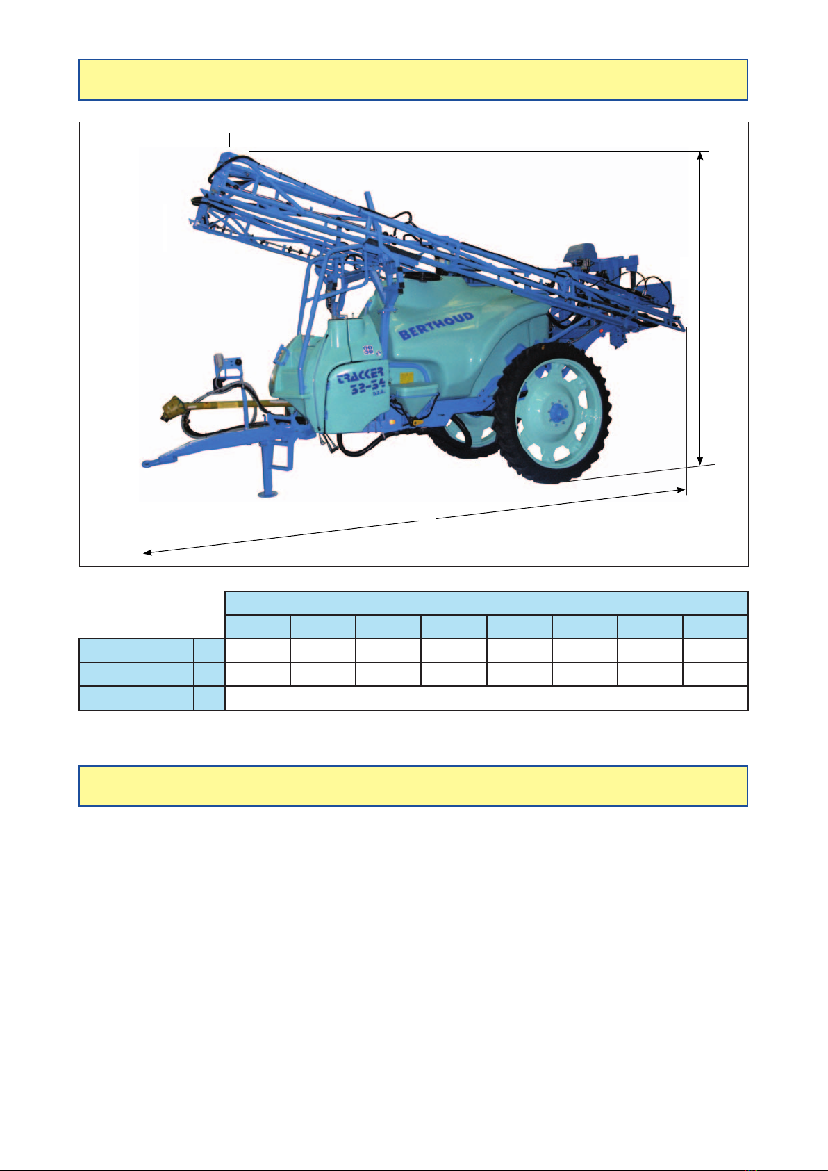
DIMENSIONS
ATMOSPHERIC NOISE EMITTED BY: Trailed sprayer TRACKER / TRACKER-S with D.P.A
regulation
-SoundpressureDriver'senvironmentLPAindB(A):
- Tractor alone = 72.2
- Tractor + sprayer = 72.6
- Sound pressure Peak level:
- Tractor alone = 97.5
- Tractor + sprayer = 100.1
-SoundpowerLWA:
- Tractor alone = 104.4
- Tractor + sprayer = 106.5
Complywiththelegislationinforceanduseear-protectorsifnecessary.
SOUND MEASUREMENTS
C
B
A
BOOMS
RLD 18 RLD 20 RLD 21 RLD 24 Axiale 24 Axiale 28 Axiale 30 Axiale 32
Overall length A6.33 m 6.33 m 6.33 m 6.33 m 7.03 m 7.03 m 8.10 m 8.10 m
Overall height B2.90 m 3.00 m 3.00 m 3.30 m 3.50 m 3.85 m 3.90 m 3.95 m
Overallwidth C2.55 m to 2.90 m according to tires, track and mudguard option
82.503 TRACKER / TRACKER-S D.P.A 7
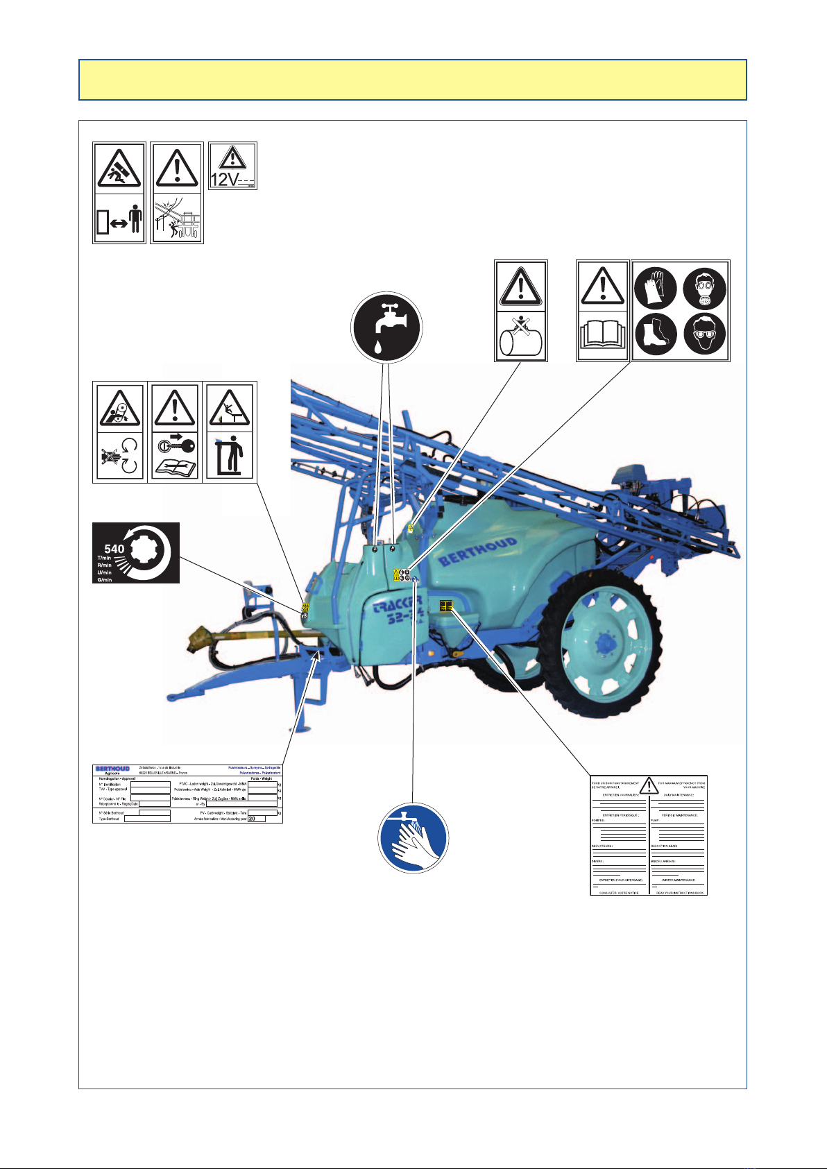
It is very important to keep the safety stickers in location and in good condition as they draw your
attention to possible dangers and refer to the operator's manual.
Check their location on the sprayer and see their meaning in manual No. 82.471 (sprayers safety,
checks and maintenance).
- TRACKER / TRACKER-S D.P.A
540
POSITION OF SAFETY STICKERS
On the chassis, front right side
On control box of the spraying
boom
8 82.503 TRACKER / TRACKER-S D.P.A
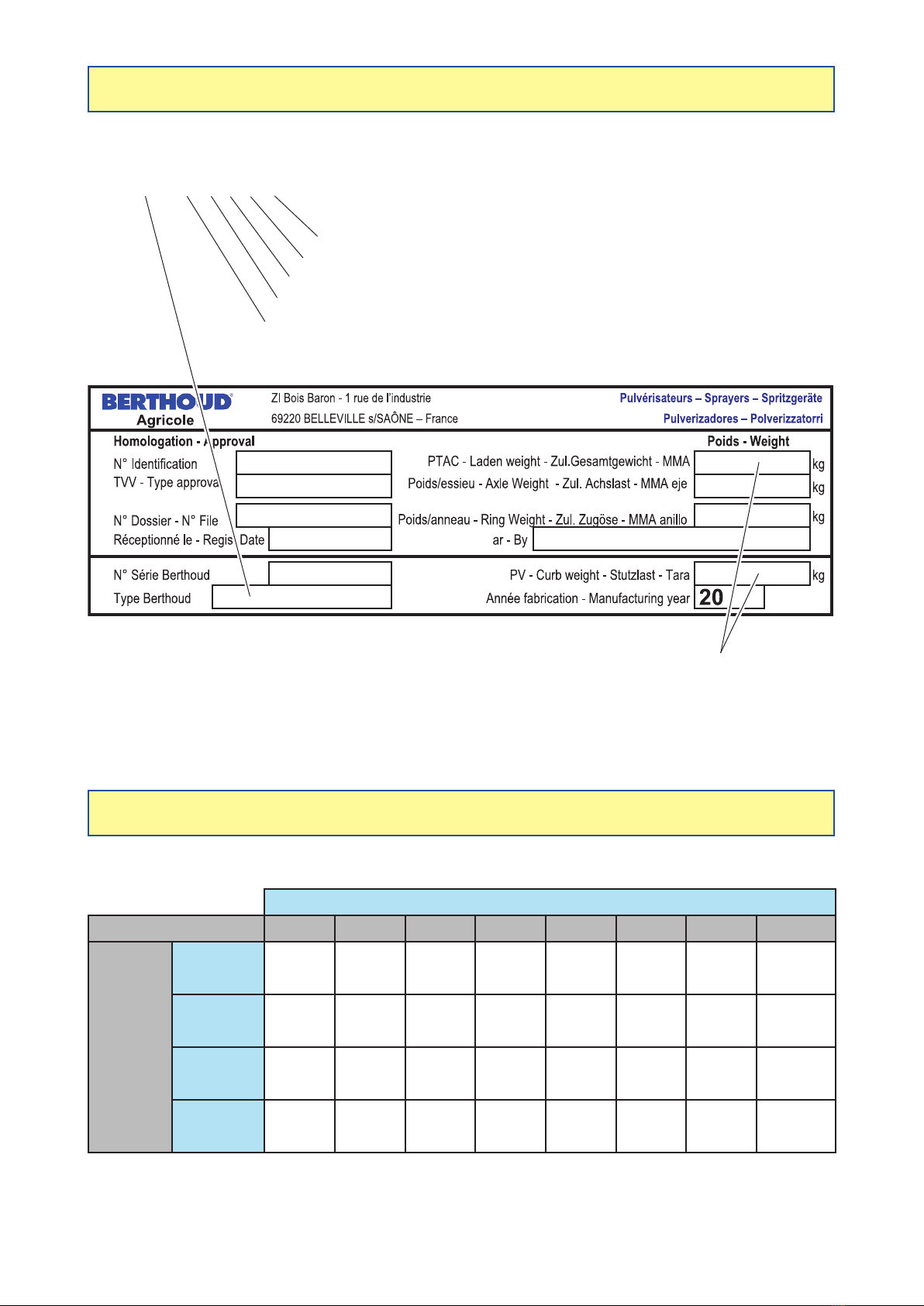
The "Kerb weight" and "Gross
vehicle weight" boxes use the data
in the table below
- The location of the descriptive plate on your sprayer is indicated on the view in page 7.
-Thebox"Type"ismadeupoflettersandgures.
- Example: TRM A 32 AX 24
24 = Width 24 metres (28 = 28 metres)
AX = AXIALE boom (RD = RLD boom)
32 = Rated capacity of the tank 3,200 litres
A= D.P.A - D.P.A TELEVOLUX regulation
TRM =TRACKER MAJOR sprayer (TRR = TRACKER RACER,
TRS = TRACKER R-XS)
DESCRIPTIVE PLATE
TABLE OF WEIGHTS (in kg)
The data below are valid for France only (see the document DREAL).
BOOMS
SPRAYER RLD 18 RLD 20 RLD 21 RLD 24 Axiale 24 Axiale 28 Axiale 30
Axiale 32/33
TRACKER
3200
Kerbweight 2,600 2,623 2,635 2,655 3,115 3,240 3,550 3,580
Gross
vehicleweight 6,425 6,455 6,470 6,495 6,955 7,025 7,390 7,410
Gross
vehicleweight
Axle 5,105 5,130 5,140 5,160 5,525 5,580 5,870 5,890
Gross
vehicleweight
Drawbar
1,320 1,325 1,330 1,335 1,430 1,445 1,520 1,520
Theseweightsareunderstoodas intheheaviest congurationofthemachinery(options, tires,regulation,
suspensions).

82.503 TRACKER / TRACKER-S D.P.A 9
STARTING-UP
THE SPRAYER
Checkingpowertake-offspeed.
Checking tractor advance speed.
Checking engine speed.
Checkingowrate/hectareusingatesttube.
Tractorwheeltraveldistance.
See "Sprayer safety, checks and maintenance" manual No. 82.471.

10 82.503 TRACKER / TRACKER-S D.P.A
2
13
2
13
21
- The length of the drive shaft may need to be adjusted to suit the tractor used with the sprayer.
- Here is the procedure to be followed once the sprayer has been hitched:
- Align the jaw of the universal joint with the shaft of the tractor's power-take off.
- Separate the two half universal joint drive shafts and couple them to the corresponding shaft, putting the
female protector on the tractor side.
- Present the two half universal joint drive shafts side by side.
- Mark and cut if necessary, being sure to leave a 10 mm clearance between the end of the tube and the
heel of the jaw.
-Carefullyledownthetwotubes.
- Grease the contact surfaces.
- Usinga hack saw,cut the protectorsto the samelengthas the half universaljoint driveshafts,which should
allow the half drive shafts to stick out 40 mm in relation to their protectors in the operating position. For
your safety, the two half universal joint drive shafts must have a minimum covering of 300 mm.
-Retthedriveshaftreadyforuse.
- The sprayers are delivered set at narrow track.
- To adjust the track:
Case TRACKER (gure1):
- Once the nuts (2) are unlocked, slide the semi-
axles (1) in the girder (3).
Case TRACKER-S (gure2):
- Once the screws and nuts (2) are unlocked, slide
the semi-axles (1) in the girder (3).
Then in the 2 cases:
- Measurethe track(accordingto thatofthetractor
and the type of crop).
IMPORTANT:
The tyres must be at equal distance in
relation to the sprayer's centre axis.
-Tightenwellthenuts(2)(gure1)orthescrews
andnuts(2)(gure2):
Tightening torque = 240 Nm.
ADAPTING THE PTO SHAFT
ADJUSTMENT OF THE TRACK WIDTH
82.503 TRACKER / TRACKER-S D.P.A 11
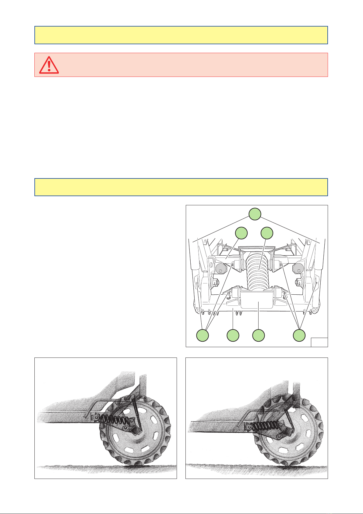
ACTIFLEX suspension in empty tank position ACTIFLEX suspension in full tank position
G
4
2 3
53
1
G
Before using your sprayer for the rst time with phytosanitary product (weedkillers,
insecticideorotherproduct),rinsethesprayercompletely.
-Removethenozzlesiftheyaretted.
- Undo the end plugs on the pipes.
- Fill 1/5th of the volume of the tank with water.
- Spray (Refer to the OPERATION chapter of the pump).
-Removeandcleanthelters.
- Retighten the pipe end plugs.
- Fit the nozzles.
NOTE: Any foreign particles which may be in the spraying circuit will thus be eliminated and there will be no
risk of them blocking the holes in the nozzles.
- The patented ACTIFLEX suspension comes as a
standard accessory on the TRACKER-S sprayer.
-Therstspringactionsuspension"delinearized"by
variable stiffness according to the load.
- The ratio and the positioning of a lever arm between
the axle (4) and the base of the spring (5) enable
the spring (3) to constantly adapt to the load (empty
tank/fulltank),toterrainconditions(path,elds,etc.)
for optimal suspension.
- Two shock absorbers (1), between the axle (4) and
the chassis (2), absorb and eliminate any remaining
oscillations.
-
Greaseviathe6greasettings(G)every100hours.
ELF EPEXA 2 or MOBILUX EP2 grease
(Warning: do not use molygraphite grease)
RINSING THE SPRAYER BEFORE FIRST USE
ACTIFLEX SUSPENSION (gure3)
12 82.503 TRACKER / TRACKER-S D.P.A
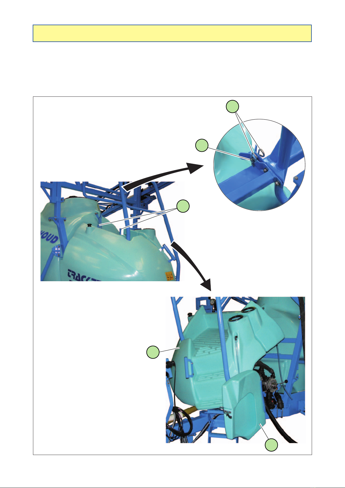
OPENING THE FAIRING
To open the fairing and reach at the control station:
- Unscrew the 2 threaded rods (1).
- Remove the pins (2) and the clevis pins (3).
- Open the protection door (5) of the control station.
- Rock the fairing assembly (4) forward.
2
3
4
5
1

82.503 TRACKER / TRACKER-S D.P.A 13
USING THE SPRAYER
See "NOZAL nozzles"
manual No. 82.467
CHOICE OF NOZZLES
AND
TABLES OF FLOW RATES
TELEVOLUXfunction(option).
See manual No. 82.470
BERJUST2000monitor(option).
See manual No. 82.441
14 82.503 TRACKER / TRACKER-S D.P.A
2
1
5
4
2
3
1
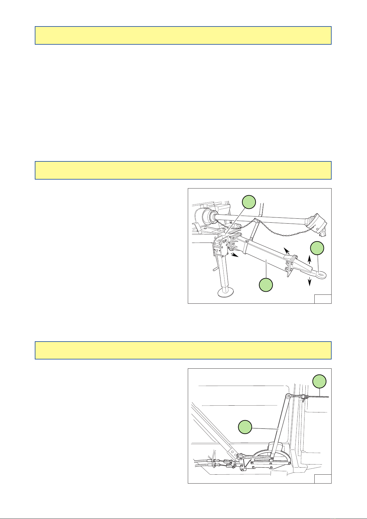
- A parking brake (2) (gure 5) is positioned on the
right-hand side of the sprayer.
- Fromthe tractorcab,you can immobilisethe sprayer
by using the rope (1) linking the brake control lever.
- Couple the sprayer’s drawbar to the tractor hook or coupling pin. The sprayer must be horizontal.
- Attach the end of the drive to the power take-off.
- Attach the small chain of the drive shaft protectors to the position intended for it.
- Raise the jackleg.
- Connect the hydraulic connections.
- Connect the electric connections.
- Release the parking brake.
-Hookthesmallrope(1)(gure5)tractorside(toimmobilisethesprayerincasethecouplingbreaks).
HITCHING THE SPRAYER TO THE TRACTOR
PARKING BRAKE
-Thisdrawbar(gure4)has4settingsfortheeye(1),
providing a total travel distance of 180 mm.
- Adjustments are made by moving the position
of the eye (1) in relation to the spacer bar (2):
(2 positions).
-Tocongurethedrawbarinpositions3and4:
▪Removetheeye(1).
▪Removethespacerbar(2)fromthedrawbar(3).
▪Turnthedrawbar(3)180°.
▪Turnthespacerbar(2)lengthwise.
▪Replace the eye (1) on the spacer bar (2) for
positions 3 and 4.
ADJUSTABLE HEIGHT DRAWBAR (Option)

82.503 TRACKER / TRACKER-S D.P.A 15
-Putthesprayeronaat,hardsurface.
- Put the sprayer in its parking position.
- Tighten the parking brake.
- Disconnect the electric connections.
- Disconnect the hydraulic connections.
- Rest the hydraulic pipes on the sprayer mountings intended for this purpose.
- Disconnect the drive shaft from the tractor.
- Rest the drive shaft on its support so as not to damage its protectors.
- Unhitch the sprayer.
UNHITCHING THE SPRAYER
- Check the condition of the protectors on the drive shafts.
- Make sure that there is no foreign matter into the tank.
- Check the oil levels and the greasing of the various elements (see "Lubrication and greasing" section).
-Checkthecleannessofthelters:
- Suction,
- delivery.
CHECKS TO BE CARRIED OUT EVERY TIME BEFORE
THE SPRAYER IS USED
CAUTION
- For your convenience,
theelectronicunithasbeenprogrammedwiththeoretical
valuescorrespondingto yoursprayer’scharacteristics.
In all cases, you must check and possibly correct the
values programmed.
WHEN STARTING
- Start-up the motor.
- Use switch (1) to power-up the unit (pages 16 and 17).
- Engage the power take-off.
CHECKS
- When starting the campaign, systematically check that the
nozzle pressure is below 3 bar for 1 minute.
- Reprogram the new value. If this is higher than the initial
value by 10%, you must replace the nozzles.
CAUTION
- ALL THE VALVE AND THE INDEXES OPERATIONS
MUST BE CARRIED OUT WITH THE POWER TAKE-OFF
STOPPED.
RECOMMENDATIONS FOR USE

16 82.503 TRACKER / TRACKER-S D.P.A
L
VALID
INSERT
DIRECT
REDUCTION
L / ha
I
0
0
0
M
PRESENTATION OF THE D.P.A CONTROL BOX
WITH TELEVOLUX (Option)
NOTE:
- Fuse: The control box (2) is protected by 3 type fuses Ø 5 mm x 20 mm:
- 5 Amps for the TELEVOLUX board (item 3),
- 10 Amps for the boom control board (item 4),
- 10 Amps for the boom spraying sections control board (item 5).
43
5
TELEVOLUX function
(See manual No. 82.470)
Control box
power switch 1
VOLUX pump
engage/disengage
control switch
72 pin plug
Power cable (battery)
Converter plug
Control switches for
options andAXIALE ED
boom
(See manual
No. 82.438)
2
Spraying control switches
(See page 28)

82.503 TRACKER / TRACKER-S D.P.A 17
Capteur
de
vitesse
Débimètre
-
+
0
0
0
PRESENTATION OF THE D.P.A CONTROL BOX
WITH BERJUST (Option)
NOTE:
- Fuse: The control box (2) is protected by 3 type fuses Ø 5 mm x 20 mm:
- 10 Amps for the boom control board (item 3),
- 10 Amps for the boom spraying sections control board (item 4),
- 3.15 Amps for the BERJUST board (item 5).
BERJUST 2000 monitor
(See manual No. 82.441)
24 or 42 pin plug
Speed sensor plug
Flowmeter plug
Control box
power switch 1
Volux pump
engage/disengage
indicator light
Power cable
(battery, 12 Vdc)
Controlpanelsupport
to be secured in the
tractor cab
AXIALE S.E.H
boom control
selector
(See manual
No. 82.438)
Switch and push-
button of the
options
2 3 4 5
18 82.503 TRACKER / TRACKER-S D.P.A
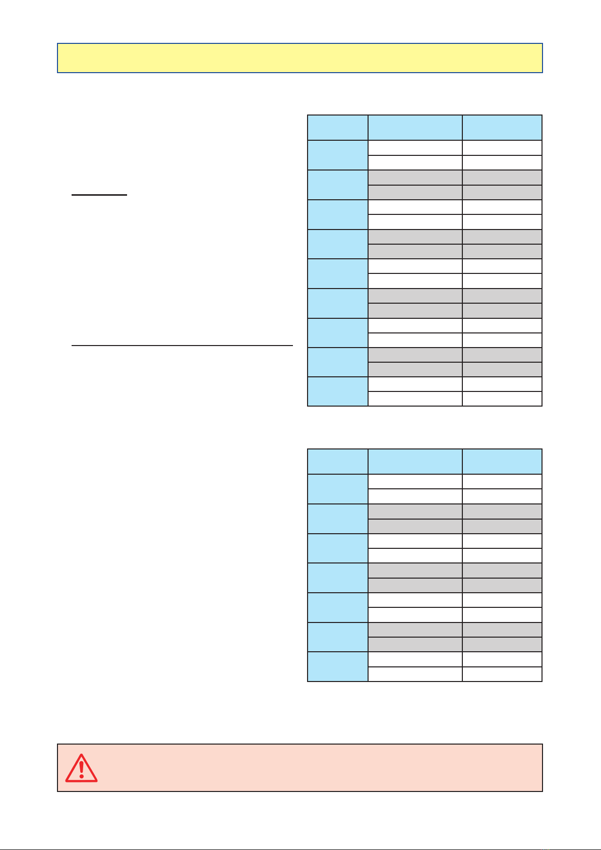
ADJUSTMENT OF FLOW RATES/HECTARE
Your sprayer is assembled with a "VOLUX" volumetric
pump which is mechanically linked by an angle
transmission, a cardan transmission and a multiplier
to the R.H. wheel rotation.
PUMP FLOW RATE CAN BE MODIFIED IN
2 WAYS
1 - MANUALLY
-Movethelever(3)(gure6)ofthemultiplier(4)
whichislocatedon theinsideofthesprayer'sright
wheel.
▪
Leverinposition(1-Tortoise)=Smallowrates/ha.
▪Leverinposition(2-Hare)=Largeowrates/ha.
▪Neutral between the 2 positions. (To move
from position (1) to the position (2), it may be
necessary to rotate the output shaft (5) by some
degrees).
▪Item (6): Protector and universal joint.
2 - BYADJUSTING THE STROKE OF THE PISTONS
(In2ways,manualorelectric)
- Manually(gure7):
The VOLUX or SUPER VOLUX pump features
twograduateddialsontheleft-handside,together
with an index.
The position of this index indicates the volume/
hectare when multiplied by 100.
Example:
If the index is on 5, the pump is set at 500 l/ha.
Settingtheindex(2):
▪Aspecial wrench and pin are used to adjust the
index.
Thewrench(1)isttedonthepumpshaft.
The pin (3) is inserted in the holes located on
the dial support ring (4).
▪Loosen the 2 nuts (5).
▪While maintaining the shaft with the wrench (1),
pivot the dial with the pin (3) and move it to the
desired graduation.
▪Tighten the 2 nuts (5).
▪Remove the wrench (1) and the pin (3).
- Electric programming (option):
The stroke of the Volux pump pistons is adjusted
using the TELEVOLUX control box (gure 8).
(See manual No. 82.470).
ENGAGEMENT/DISENGAGEMENT OF THE VOLUX PUMP
-Usetheengage/disengageswitchorselector(1)(gure8)locatedontheTELEVOLUXcontrolpanel(indicator
on).
CAUTION: When not used for spraying operations, the VOLUX pump must be disengaged.
(Actuate the switch or the electric selector (1)). Never engage or disengage the VOLUX
pumpwhiledriving.
Boom
width
Required
owrate/hectare
Position of the
lever(3)(gure6)
12 metres from 0 to 700 l/ha 1 - Tortoise
from 700 to 1300 l/ha 2 - Hare
15 metres from 0 to 560 l/ha 1 - Tortoise
from 560 to 1000 l/ha 2 - Hare
16 metres from 0 to 530 l/ha 1 - Tortoise
from 530 to 950 l/ha 2 - Hare
18 metres from 0 to 470 l/ha 1 - Tortoise
from 470 to 830 l/ha 2 - Hare
20 metres from 0 to 425 l/ha 1 - Tortoise
from 425 to 750 l/ha 2 - Hare
21 metres from 0 to 400 l/ha 1 - Tortoise
from 400 to 700 l/ha 2 - Hare
24 metres from 0 to 350 l/ha 1 - Tortoise
from 350 to 650 l/ha 2 - Hare
28 metres from 0 to 300 l/ha 1 - Tortoise
from 300 to 550 l/ha 2 - Hare
30 metres from 0 to 280 l/ha 1 - Tortoise
from 280 to 500 l/ha 2 - Hare
Boom
width
Required
owrate/hectare
Position of the
lever(3)
20 metres from 0 to 535 l/ha 1 - Tortoise
from 535 to 950 l/ha 2 - Hare
21 metres from 0 to 510 l/ha 1 - Tortoise
from 510 to 905 l/ha 2 - Hare
24 metres from 0 to 450 l/ha 1 - Tortoise
from 450 to 800 l/ha 2 - Hare
28 metres from 0 to 380 l/ha 1 - Tortoise
from 380 to 680 l/ha 2 - Hare
30 metres from 0 to 360 l/ha 1 - Tortoise
from 360 to 630 l/ha 2 - Hare
32 metres from 0 to 335 l/ha 1 - Tortoise
from 335 to 600 l/ha 2 - Hare
36 metres from 0 to 300 l/ha 1 - Tortoise
from 300 to 525 l/ha 2 - Hare
Flowrate/hectaretable
for VOLUX pump
Flowrate/hectaretable
for SUPER VOLUX pump

82.503 TRACKER / TRACKER-S D.P.A 19
2
45
3
1
8
6
7
56
4
3
1
2
BERTHOUD
L
VALID
INSERT
DIRECT
REDUCTION
L / ha
TELEVOLUX
I
0
00
0
1
L
VALID
INSERT
DIRECT
REDUCTION
L / ha
I
0
0
0
M
1

20 82.503 TRACKER / TRACKER-S D.P.A
ADJUSTMENT OF THE COMPENSATED RETURN (V.M.m)
SETTING OF TRACKER D.P.A USING MULTIRETURN UNITS
-Inthiscase,theTRACKERdistributorunitismadeupofmotorisedvalves(V.M.m)(4)(gure9)foreachboom
section.
- These valves supply each boom section when they are in "open" position and the return to the tank when
they are in "closed" position.
-
Return to the tank is calibrated by means of multireturns.
- The setting of the multireturns to the tank is set using the table below because this will depend on nozzle type
used and the number of nozzles per boom section.
TABLE FOR SETTING OF MULTIRETURN UNITS
NOZZLE TYPE
Position of crownwheel (with red numbers)
6
nozzle
section
7
nozzle
section
8
nozzle
section
9
nozzle
section
10
nozzle
section
12
nozzle
section
15
nozzle
section
18
nozzle
section
AFX/RFX/ALX/KWIX - green 80° 1.7 2.0 2.2 2.4 2.5 2.8 3.1 3.5
AFX/RFX/ALX/KWIX - yellow 80° 2.2 2.4 2.6 2.8 3.0 3.3 3.7 4.1
AFX/RFX/ALX/KWIX - blue 110° 2.8 3.0 3.3 3.5 3.7 4.1 4.6 5.1
AFX/RFX/ALX/KWIX - red 110° 3.3 3.5 3.8 4.2 4.3 4.8 5.4 6.0
AFX/RFX/ALX/KWIX - brown 110° 3.7 4.0 4.3 4.6 4.9 5.4 6.1 6.8
AFX/RFX/ALX/KWIX - grey 110° 4.1 4.4 4.8 5.1 5.4 6.0 6.8 7.6
AFX/RFX/ALX/KWIX - white 110° 4.8 5.2 5.6 6.0 6.4 7.0 8.0 8.9
INOX 6/10 - white propeller 0.7 0.8 0.9 1.1 1.2 1.4 1.7 2.0
INOX 8/10 - white propeller 0.9 1.1 1.3 1.4 1.6 1.8 2.2 2.5
INOX 10/10 - white propeller 1.2 1.4 1.6 1.8 1.9 2.2 2.5 2.8
INOX 12/10 - white propeller 1.5 1.8 2.0 2.2 2.3 2.6 2.9 3.2
INOX 15/10 - white propeller 1.9 2.1 2.3 2.5 2.6 2.9 3.3 3.6
INOX 18/10 - white propeller 2.3 2.5 2.7 2.9 3.1 3.4 3.8 4.2
INOX 15/10 - black propeller 2.7 2.9 3.1 3.3 3.5 3.9 4.4 4.9
INOX 18/10 - black propeller 3.1 3.4 3.6 3.9 4.1 4.6 5.2 5.7
INOX 20/10 - black propeller 3.4 3.7 4.0 4.2 4.5 5.0 5.7 6.3
INOX 25/10 - black propeller 3.7 4.0 4.3 4.6 4.9 5.4 6.1 6.7
INOX 30/10 - black propeller 4.2 4.6 5.0 5.4 5.6 6.3 7.0 7.8
KWIX 3-holes - yellow 2.2 2.4 2.6 2.8 3.0 3.3 3.7 4.1
KWIX 3-holes - blue 2.8 3.0 3.3 3.5 3.7 4.1 4.6 5.1
KWIX 3-holes - red 3.3 3.5 3.8 4.2 4.3 4.8 5.4 6.0
KWIX 3-holes - brown 3.7 4.0 4.3 4.6 4.9 5.4 6.1 6.8
KWIX 3-holes - grey 4.1 4.4 4.8 5.1 5.4 6.0 6.8 7.6
KWIX 3-holes - white 4.8 5.2 5.6 6.0 6.4 7.0 8.0 8.9
SETTING THE MULTIRETURN UNITS (gure9)
- Slacken nut (1).
- Turn crownwheel (2).
- Place selected mark in front of index (3).
- Tighten nut (1).
Example:
If RedAFX/RFX/KWIX nozzles are used, and if your sprayer is equipped with a boom of 24 metres (4 sections
of 12 nozzles), you must place the multireturn units at position 4.8.
This manual suits for next models
1
Table of contents
Other Berthoud Farm Equipment manuals


Popular Farm Equipment manuals by other brands

Nutriculture
Nutriculture Amazon Aeroponic System Assembly and operating instruction

Colombo
Colombo Twin Master owner's manual

Holzmann
Holzmann HUB25KG user manual

Aitchison
Aitchison Reese Agri UFO SEEDKING Professional manual

GREAT PLAINS
GREAT PLAINS 1205NT Predelivery Manual

Degelman
Degelman Pro-till 26 quick start guide


