Sola ARES-2713 How to use

WWW.SOLAGRUPO.COM
ARES-2713
MAINTENANCE AND DOSAGE
STARTING
MANUAL
Pneumatic seed drill

2
,62
%85($89(5,7$6
&HUWLILFDWLRQ
SOLÀ seed drills and fertilizer spreaders are manufactured in a highly specialized environment and our
factory has a vast customer-endorsed experience.
SOLÀ machines use highly advanced technology and are guaranteed to work without malfunction in a
great variety of conditions. They are provided with easy-to-use and ecient devices.
SOLÀ machines perform excellently with only minimum operator maintenance.
This manual will help you use your SOLÀ product with the utmost eciency.
Certied quality system
2nd Edition – September 2016
Ref.: CN-811082/GB
Created by: M.A SOLÀ, S.L.
It is forbidden to copy any part of this manual.
Specications are subject to change or modication without notice.
The pictures included do not necessary show the standard version.

3
TABLE OF CONTENTS
1 INTRODUCTION......................................................................................................................................5
2. GENERAL DESCRIPTION OF THE MACHINE ...........................................................................................6
2.1 OVERVIEW...............................................................................................................................................................6
2.2 STANTDARD EQUIPAMENT.................................................................................................................................6
2.3 OPTIONAL EQUIPAMENT ....................................................................................................................................6
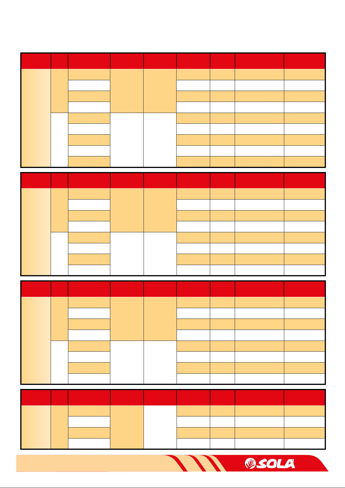
2.4 TECHNICAL CHARACTERISTICS.........................................................................................................................7
3 SAFETY INSTRUCTIONS .........................................................................................................................8
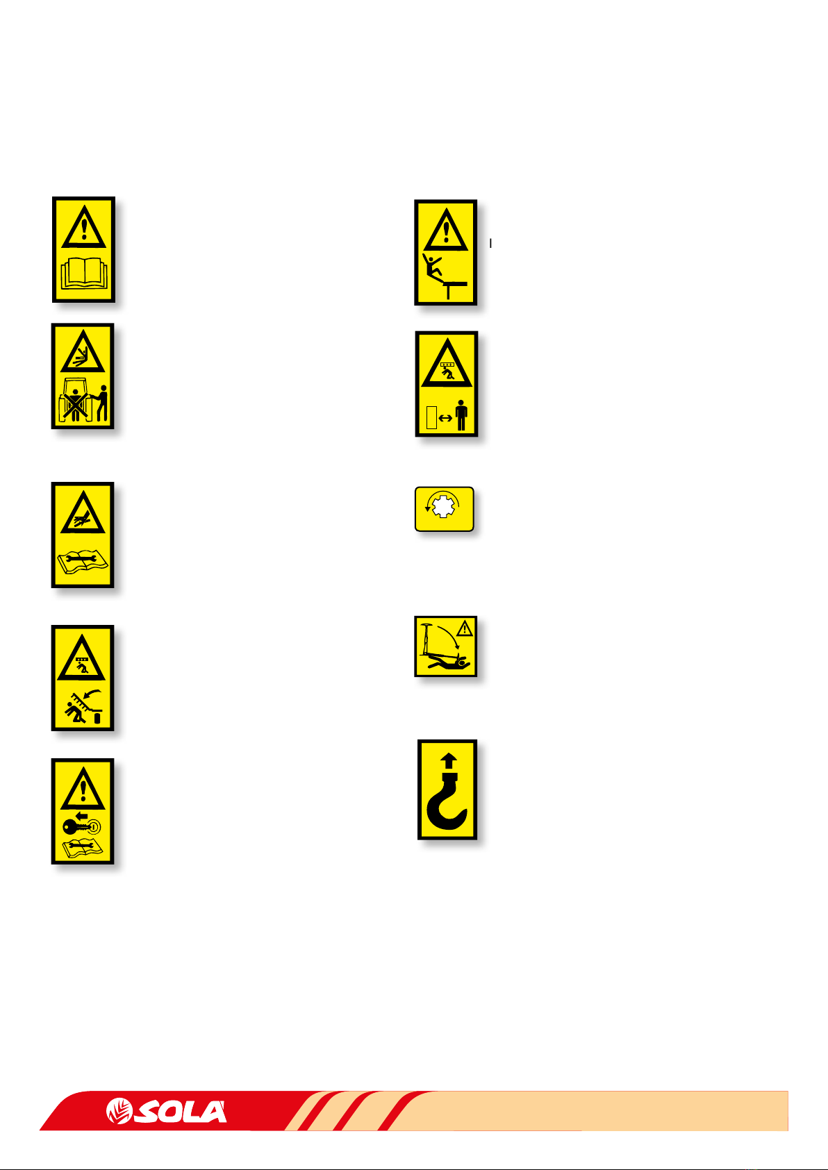
3.1 SAFETY SYMBOLS .................................................................................................................................................8
3.2 USE ACCORDING TO DESIGN..............................................................................................................................8
3.3 GENERAL SAFETY INSTRUCTIONS....................................................................................................................9
4 ESSENTIAL SOWING CONCEPTS ..........................................................................................................10
4.1 TERRAIN .................................................................................................................................................................10
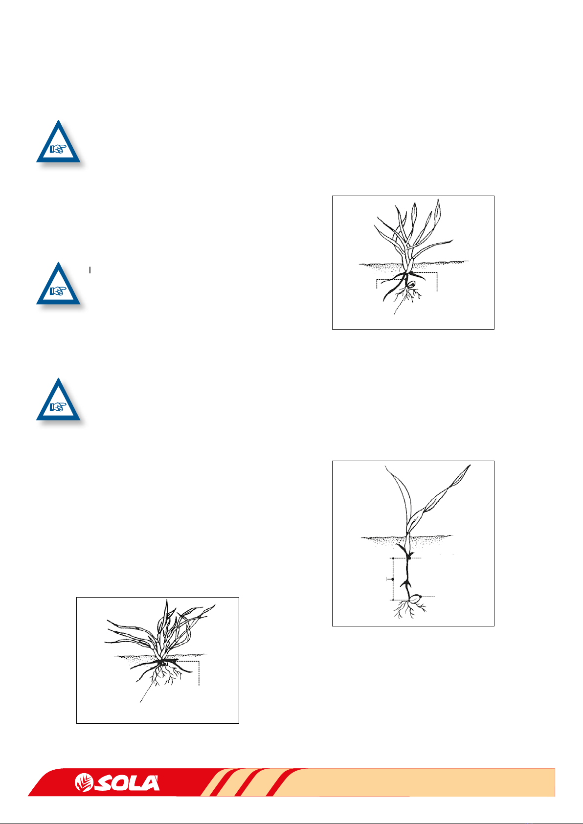
4.2 THE SEED...............................................................................................................................................................10
4.3 SEED PLANTING DEPTH ....................................................................................................................................10
5. STARTING..............................................................................................................................................12
5.1 COUPLING THE SEED DRILL..............................................................................................................................12
5.2 HYDRAULIC CONNECTIONS ............................................................................................................................12
5.2.1 HYDRAULIC SYSTEM...............................................................................................................13
5.3 TRANSPORT POSITION ......................................................................................................................................14
5.4 LOADING THE SEED DRILL MANUALLY..........................................................................................................14
5.5 THE BUILTIN SUPPORTING LEGS....................................................................................................................14
6. DOSAGE ................................................................................................................................................15
6.1 REGULAR SEEDS POSITION N ........................................................................................................................16
6.2 FINE SEEDS MICRODOSING POSITION F..................................................................................................16
6.3 PREVIOUS FLOW TEST........................................................................................................................................17
6.4 COMPLEMENTARY CHECKING TESTS .............................................................................................................18
6.4.1 TEST TO DETERMINE THE NUMBER OF WHEEL TURNS...................................................18
6.4.2 SEED DOSING ADJUSTMENTS ..............................................................................................19
7 ADJUSTING SEED PLANTING DEPTH...................................................................................................20
7.1 ADJUSTING RATCHETS AND SPINDLES......................................................................................................... 20
7.2 INCLINATION OF THE FOLDING PARTS......................................................................................................... 20
7.3 TRACK ERASERS...................................................................................................................................................21
7.4 LEVELLER OPTIONAL .......................................................................................................................................21
7.5 SEEDING ARM.......................................................................................................................................................21
7.5.1 TINE COULTER ...........................................................................................................................21
7. 5. 2 P T .................................................................................................................................................21
7.5.3 DISCO......................................................................................................................................... 22
7.5.4 SUFFOLK COULTERS ............................................................................................................... 22
7. 6 H A R R OW ............................................................................................................................................................... 22
7.7 HYDRAULIC TRACK MARKERS......................................................................................................................... 23
7.7.1 ADJUSTING TRACK MARKER’S LENGTH. ............................................................................ 23
7.7.2 ADJUSTING TRACK MARKER’S INCLINATION ................................................................... 23
8 TYPES OF DISTRIBUTION.....................................................................................................................24
8.1 SEED DISTRIBUTION BY MECHANICAL FAN................................................................................................. 24
8.2 SEED DISTRIBUTION BY HYDRAULIC FAN.................................................................................................... 24

4
9- ELECTRONICAL CONTROLLER ...............................................................................................................25
9.1 FRONT PANEL DESCRIPTION............................................................................................................................. 25
9.2 FORWARD SPEED – C1........................................................................................................................................ 25
9.3 TOTAL AREA / SEED DRILL WIDTH – C2........................................................................................................... 26
9.4 CONTROL PANEL WITH MARKER PATHS (OPTIONAL) .................................................................................. 26
9.4.1 TRAMLINING - C3 ..................................................................................................................... 26
9.5 FAN RPM / FAN ALARMS – C4............................................................................................................................ 29
9.6 SEED SHAFT RPM – C5........................................................................................................................................ 29
9.7 HOPPER LOW LEVEL ALARM – C6..................................................................................................................... 29
9.8 TOTAL SOWING SHUT-OFF (OPTIONAL) ......................................................................................................... 30
9.9 SHUT-OFF SOWING FROM FOLDING PARTS (OPTIONAL)............................................................................ 30
10 MAINTENANCE ...................................................................................................................................31
10.1 CHECKING FREQUENCY...................................................................................................................................31
10.2 LUBRICATION.....................................................................................................................................................32
10.3 DISTRIBUTOR HEAD AND SEED HOSES .......................................................................................................32
10.4 TYRES PRESSURE...............................................................................................................................................32
11 DOSAGE TABLES .................................................................................................................................33
12 WARRANTY.........................................................................................................................................35

5
1. INTRODUCTION
It is essential to read and follow the instructions and recom-
mendations in this manual before operating the seed drill
ARES-2713. Careful reading enables maximum operator ef-
ciency, prevents accidents and damage, and increases the
seed drill’s capacity and life expectancy.
The manual should be read by everyone performing opera-
tional (including preparation, repairs in the eld and general
care of the machine), maintenance (inspection and technical
assistance) and transportation tasks.
Please ensure that this manual has been read by any per-
son involved in performing operational tasks, (including
preparation, dealing with mechanical problems and super-
vising the machine), maintenance (inspection and techni-
cal assistance) and transport.
For your safety, please follow these technical safety instruc-
tions as SOLÀ will not be responsible for damages caused by
not observing the information provided.
In the rst chapters you will nd the Technical Characteris-
tics and Safety Instructions, as well as some essential sowing
concepts. Basic concepts that are required to operate the
machine are explained in the Starting and Maintenance sec-
tions.
The last part of this manual consists of Dosage Tables, detailed by
seed type.
SOLÀ RETAINS THE RIGHT TO MODIFY ILLUS
TRATIONS, TECHNICAL DATA AND WEIGHTS
INDICATED IN THIS OPERATING MANUAL,
IF THESE CHANGES HELP TO IMPROVE THE
QUALITY OF THE SEED DRILLS.
In this operating manual you will nd three dierent symbols relating to safety:
TO WORK MORE EASILY WITH THE SEED DRILL.
TO PREVENT DAMAGE TO THE SEED DRILL AND OPTIONAL EQUIPMENT.
TO PREVENT PHYSICAL INJURY.

6
2- GENERAL DESCRIPTION OF THE MACHINE
2.1 OVERVIEW
2.2 STANTDARD EQUIPAMENT
- Hopper with a capacity of 1600 or 2000 litres.
- Selector screen.
- Weigher, crank and grain counter.
- Tractor track eraser and seed drill or rear cultivator.
- Independent hydraulic track markers.
- Monitor with fan rpm counter, distributor turning alarm,
hopper seed level sensor, and hectare counter.
- Signal, marker, brake and clearance lamps.
- Work lamps.
- Rear harrow in three lengths.
- Mechanical fan with cardan transmission at 1000 rpm or
fan with hydraulic motor.
- Floating wheels 10.0/75-15.3 with mud scrapers.
- Wheels on the folding parts for depth control (* availa-
ble for models 500 and 600 only).
2.3 OPTIONAL EQUIPAMENT
- Central wheels for depth control.
- Mud scrapers for the depth-control wheels on folding
parts.
- Individual depth control wheel for each row (available
for the DISC model only).
- Flat or tine leveller in three lengths.
- Electric transmission with radar or GPS.
- Total power cutout.
- Shut-o sowing from dependent or independent fol-
ding parts or shut-o half machine.
- Tramlines.
- Microgranulator kit (400 additional litres).
- Pre-emergence track markers.
- Independent hydraulic kit.
ACCESS
LADDER
DEPTH
ADJUSTMENT
HOPPER
DEPTH CONTROL
WHEELS
LEVELLERHARROW ROWS
FLOATING
WHEELS
FAN
CULTIVATOR OR
TRACK ERASERS
WORK LIGHTS HYDRAULIC
BLOCK
METERING BOX
SIGNAL
LAMPS
TRACK MARKERS

7
2.4 TECHNICAL CHARACTERISTICS
TYPE OF
MACHINE LINES WORKING WIDTH
cm) / ROWS
SPACING ROW
(cm)
HOPPER
CAPACITY (L.)
TRANSPORT
WIDTH (m)
HEIGHT
MAX. (m)
TARE WITH
TRACK ERASER (kg)
TARE WITH
CULTIVATOR (kg)
TINE
COULTER
3
400/32
12,5
1.600
or
2.000
3,05 2,40
450/36 3,05 2,40
500/40 3,05 2,60
600/48 3,05 3,05 1.801 2.284
4
400/32
12,5
1.600
or
2.000
3,05 2,40
450/36 3,05 2,40
500/40 3,05 2,60
600/48 3,05 3,05 1.960
700/48 3,05 3,55 2.040
TYPE OF
MACHINE LINES WORKING WIDTH
cm) / ROWS
SPACING ROW
(cm)
HOPPER
CAPACITY (L.)
TRANSPORT
WIDTH (m)
HEIGHT
MAX. (m)
TARE WITH
TRACK ERASER (kg)
TARE WITH
CULTIVATOR (kg)
SUFFOLK
2
400/32
12,5
1.600
or
2.000
3,05 2,40
450/36 3,05 2,40
500/40 3,05 2,75 2.338
600/48 3,05 3,20
3
400/32
12,5
1.600
or
2.000
3,05 2,40
450/36 3,05 2,40
500/40 3,05 2,60
600/48 3,05 3,05
TYPE OF
MACHINE LINES WORKING WIDTH
cm) / ROWS
SPACING ROW
(cm)
HOPPER
CAPACITY (L.)
TRANSPORT
WIDTH (m)
HEIGHT
MAX. (m)
TARE WITH
TRACK ERASER (kg)
TARE WITH
CULTIVATOR (kg)
DISCS 2
400/32
12,5
1.600
or
2.000
3,05 2,40
450/36 3,05 2,40
500/40 3,05 2,75
600/48 3,05 3,20
TYPE OF
MACHINE LINES WORKING WIDTH
cm) / ROWS
SPACING ROW
(cm)
HOPPER
CAPACITY (L.)
TRANSPORT
WIDTH (m)
HEIGHT
MAX. (m)
TARE WITH
TRACK ERASER (kg)
TARE WITH
CULTIVATOR (kg)
PT
3
400/32
12,5
1.600
or
2.000
3,05 2,40
450/36 3,05 2,40
500/40 3,05 2,60
600/48 3,05 3,05
4
400/32
12,5
1.600
or
2.000
3,05 2,40
450/36 3,05 2,40
500/40 3,05 2,60
600/48 3,05 3,05

8
3. SAFETY INSTRUCTIONS
3.1 SAFETY SYMBOLS
On the machine you will nd the following warning pictograms:
READ THE INSTRUCTIONS CAREFULLY AND
OBSERVE THE SAFETY ADVICE GIVEN IN THE
OPERATING MANUAL.
DURING THE COUPLING MANOEUVRE, STAY
AWAY FROM THE REAR PART OF THE TRAC
TOR.
RISK OF SERIOUS PHYSICAL INJURY.
DANGER OF INFECTION FROM ESCAPING
HYDRAULIC FL UID AT HIGH PRESSURE! THIS
CAN INFL ICT SERIOUS INJURIES WITH POTEN
TIALLY FATAL CONSEQUENCES IF IT PASSES
THROUGH THE SKIN AND INTO THE BODY.
KEEP THE HOSE LINES IN GOOD CONDITION.
RISK OF SERIOUS PHYSICAL INJURY.
NEVER STAND UNDER THE SOWING EQUIP
MENT OR SWIVEL AREA OF THE MACHINE’S
EXTENSION TINE COULTERS.
RISK OF SERIOUS PHYSICAL INJURY.
WHILE MAINTAINING OR REPAIRING THE SEED
DRILL, STOP THE TRACTOR’S ENGINE AND
PREVENT IT FROM STARTING. THE IGNITION
KEY MUST BE REMOVED.
IT IS FORBIDDEN TO RIDE ON THE MACHINE
DURING OPERATION.
RISK OF SERIOUS PHYSICAL INJURY.
RISK OF BEING CRUSHED WHEN WORKING
UNDER THE MACHINE, PLEASE SECURE THE
MACHINE TO PREVENT THIS RISK.
RISK OF SERIOUS PHYSICAL INJURY.
THE DIRECTION AND SPEED THAT THE PTO
SHAFT TURNS ONLY IN MACHINES EQUIPPED
WITH MECHANICAL FAN.
NEVER STAND UNDER THE TRACK MARKERS
NOR INSIDE THEIR ACTION AREA.
RISK OF SERIOUS PHYSICAL INJURY.
COUPLING POINT FOR TRANSPORTATION BY
CRANE.
540 rpm
1000 rpm
2.2 USE ACCORDING TO DESIGN
- The Seed Drill ARES-2713 has been designed for cereal
and other kind of grain seeds.
- If the machine is used in circumstances other than the
above, the manufacturer will not be held responsible for
any damage caused.
- The user must observe all regulations concerning safety,
trac and hygiene.
- If the machine is modied by the user, the manufacturer’s
warranty is cancelled. SOLÁ will not be held responsible
for any damage caused.

9
2.3 GENERAL SAFETY INSTRUCTIONS
BEFORE STARTING THE MACHINE, PLEASE
CHECK THE MACHINE IS IN GOOD CONDI
TION FOR WORK AND IS SAFE FOR ROAD
USE.
CHECK THAT VISIBILITY IS CLEAR AROUND
THE MACHINE AND THERE IS NO PERSON IN
THE WORKING AREA.
IN THOROUGHFARE, PLEASE OBSERVE
TRAFFIC SIGNS AND REGULATIONS.
IT IS FORBIDDEN TO RIDE ON THE MACHINE
OR CLIMB INTO THE MACHINE WHEN IT IS
RUNNING.
BEFORE USING THE MACHINE, THE USER
MUST BE FAMILIAR WITH ALL OPERATING
ELEMENTS.
PLEASE BE EXTREMELY CAREFUL WHEN
COUPLING AND UNCOUPLING THE MA
CHINE TO THE TRACTOR.
PLEASE CHECK THAT THE PTO SHAFT IS IN
GOOD CONDITION AND WELL PROTECT
ED. PREVENT THE PROTECTIVE TUBE FROM
TURNING BY HOLDING BOTH THE TUBE
AND CHAIN PROVIDED FOR THIS PURPOSE.
MOUNT THE PTO SHAFT’S TRANSMISSION
ONLY WHEN THE TRACTOR’S ENGINE IS OFF.
BEFORE CONNECTING THE PTO SHAFT, BE
SURE THAT THE DANGER ZONE SURROUND
ING THE MACHINE IS CLEAR.
NEVER LEAVE THE TRACTOR’S DRIVER’S SEAT
WHILE THE MACHINE IS IN OPERATION.
DO NOT DEPOSIT EXTERNAL ELEMENTS IN
SIDE THE HOPPER.
WHEN MANTAINING THE HYDRAULIC SYS
TEM OF THE SEED DRILL, MAKE SURE THAT
IT IS DEPRESSURISED AND THE TRACTOR’S
ENGINE IS OFF.
PLEASE REGULARLY CHECK THE CONDITION
OF THE TUBES AND HOSEPIPES IN THE HY
DRAULIC SYSTEM. THESE PARTS AGE NATU
RALLY AND THEIR LIFE SHOULD NOT EXCEED
6 YEARS. PLEASE REPLACE WHEN NECES
SARY.
WHEN RAISING THE SEED DRILL, THE FRONT
AXLE IS UNLOADED. ENSURE THAT THE MA
CHINE HAS ENOUGH LOAD TO PREVENT IT
OVERTURNING. AT THIS TIME YOU MUST EN
SURE THAT THE CONDITION OF BOTH THE
STEERING AND THE BRAKES IS OPTIMAL.
DURING TRANSIT WITH THE RAISED SEED
DRILL, BLOCK THE LOWERING SWITCH. BE
FORE LEAVING THE TRACTOR, LOWER THE
SEED DRILL ONTO THE GROUND AND RE
MOVE THE TRACTOR’S STARTING KEY.
ALWAYS USE ENOUGH SUPPORTING ELE
MENTS WHEN MAINTAINING THE MACHINE
IN A RAISED POSITION TO PREVENT THE MA
CHINE FROM LOWERING OR FALLING.

10
4. ESSENTIAL SOWING CONCEPTS
4.1 TERRAIN
THE BETTER THE SOIL CONDITION, THE BET
TER THE SOWING QUALITY. WORK IS MORE
DIFFICULT ON BIG CLODS OR UNEVEN FUR
ROWS. ALTHOUGH SOLÀ MACHINES RESIST
HARSH CONDITIONS, IF THE SEEDBED DOES
NOT SATISFY APPROPRIATE CONDITIONS
THEN THE SOWING QUALITY WILL SUFFER.
4.2 THE SEED
IT IS ESSENTIAL THAT SEEDS ARE WELL MAIN
TAINED AND CLEAN. BARLEY SEEDS SHOULD
BE TRIMMED.
4.3 SEED PLANTING DEPTH
THE RECOMMENDED SEED PLANTING
DEPTHS ARE FROM 3 TO 5 CENTIMETRES.
PLANTING TOO DEEP CAUSES PROBLEMS AS
RHIZOME CANNOT REACH THE SURFACE AND
THE PLANT WILL DIE. IT DOES NOT MATTER
THAT SOME GRAINS ARE VISIBLE BECAUSE
THE HARROW’S. TINES WILL COVER THEM
EVENTUALLY.
The seed planting depth has consequences for tillering, as
well as for the plant’s strength and its ability to resist frost-
bite or drought. The parent shoot grows from 1 to 2 cm un-
der the ground, whatever the depth of the seed.
Planting deeper does not necessarily mean getting deeper
roots. Only a few roots grow from the lower part of the seed.
Most of them grow from a parent shoot close to ground level.
Tillering node
SEED
Normal Planting Depth: from 2 to 4 cm
• Thick stem, short rhizome and resistant to frostbite.
• Multiple tillering providing from 3 to 6 shoots and a lot of
blades, from 6 to 10.
• Deep and thick roots, approximately 5 cm in width and 10-
12 cm in depth.
• With less grains per sowing square metre, more ears are ob-
tained.
SEED
Rhizome Tillering node
Deeper Planting: from 5 to 6 cm
• Fine stem, rhizome exposed to frostbite.
• Late and weak tillering, 1 or zero shoots and only a few
blades, 3-4 aprox.
• Medium quality roots of approximately 3 cm in width and
5 cm in depth.
• More grains per sowing square metre are required to ob-
tain the same number of ears as in the previous case.
SEED
Tillering node
Rhizome
Very deep planting: from 8 to 10 cm
• Very ne stem. No tillering and only one blade.
• Seed runs out of supplies by growing a long rhizome
which frostbite can easily cut.
• The plant takes weak roots, approximately 1 cm in width
and 3 cm in depth.
• Twice the number of grains per sowing metre are required
to obtain the same number of ears as in the rst case.

11
WARNING
IN VERY COLD PLACES, REPEATED FROSTBITE
CAN HAVE A HONEYCOMB EFFECT ON THE
GROUND’S MOST SUPERFICIAL LAYER. IN THIS
CASE THE PLANT’S VERY FIRST ROOTS CAN
LOOSEN AND THE PLANT WILL DIE. SLIGHTLY
DEEPER PLANTING IS RECOMMENDED AND IF
POSSIBLE, THE USE OF ROLLERS TO COMPACT
THE EARTH TO BETTER PROTECT THE SEEDS.
WHEN STARTING THE MACHINE, FURROWS
WILL NOT CONTAIN ANY SEEDS FOR A METRE.
WHEN STOPPING THE MACHINE, SEEDS
WHICH WERE PREVIOUSLY INSIDE THE SEED
HOSES, SLIDE FROM THE MACHINE AND END
UP PILED ON THE GROUND. TAKE THIS INTO
ACCOUNT WHEN STOPPING AND STARTING
THE MACHINE IN ORDER TO ACHIEVE MORE
ACCURACY.
ALWAYS WORK AT A UNIFORM SPEED AS SUD
DEN ACCELERATING AND SLOWING DOWN
WILL CAUSE AN IRREGULAR SEED DISTRIBU
TION.

12
5. STARTING
5.1 COUPLING THE SEED DRILL
Seed drill ARES-2713 is supplied with a three-point linkage
of category 3.
MAKE SURE THAT NO PERSON OR OBJECT
IS EVER BETWEEN THE SEED DRILL AND THE
TRACTOR WHEN COUPLING BOTH MACHINES.
TO COUPLE THE SEED DRILL AND THE TRAC
TOR, FOLLOW THESE STEPS:
Place the fast-locking balls in the two lower bolts.
Next, couple the fertilizer using the three-point linkage.
Once the seed drill is coupled with the tractor, THE PTO
SHAFT SHOULD BE ADAPTED:
1- Dismount and insert one end into the tractor’s universal
joint shaft and the other end into the seed drill.
Look for the minimal movement length “L” by raising and
lowering the hydraulic lift.
2- Cut the spare plastic and metal into parts of the same
length and remount the PTO shaft.
3- Operate the hydraulic lift and check that the PTO shaft’s
movement is correct.
4- Secure the PTO shaft using the chain.
5- Connect the hydraulic hoses and the electrical connector
to the tractor. Feed the monitor cable into the tractor ca-
bin and connect the monitor.
WHEN OPERATING THE PTO SHAFT CHECK
THAT THE ENGINE IS OFF. ALWAYS WORK WITH
THE PTO SHAFT PROTECTED AND IN GOOD
CONDITION. PREVENT THE PTO SHAFT’S TUBE
FROM TURNING BY SECURING IT WITH THE
CHAIN PROVIDED.
WHEN LOWERING THE SEED DRILL TO THE
GROUND, UNPLUG THE TRACTOR’S UNIVERSAL
JOINT SHAFT SO THAT THE PTO SHAFT DOES
NOT HAVE AN EXCESSIVE INCLINATION (MAX.
35º).
WHEN HOLDING THE TRACTOR UNIVERSAL
JOINT SHAFT’S CLUTCH IN, PERFORM IT GEN
TLY. STARTING SUDDENLY COULD SERIOUSLY
DAMAGE THE SEED DRILL.
5.2 HYDRAULIC CONNECTIONS
To use the machine’s hydraulic connections you will need:
• WHEN FOLDING AND UNFOLDING THE MACHINE: a
double-acting connection.
• WHEN FOLDING AND UNFOLDING THE TRACK MARK-
ERS: a double-acting connection.
• If the machine has HYDRAULIC FAN: an extra single-act-
ing (connection) and a free return line.

13
COLOUR OF
THE CAP DESCRIPTION
BLUE Track marker’s hydraulic system.
GREEN Hydraulic system to fold and unfold the sowing equip-
ment
RED Service brake’s hydraulic system.
FOR THE FREE RETURN LINE CONNECTION
USE THE PLUG-ADAPTER PROVIDED.
5.2.1 HYDRAULIC SYSTEM
FOLDING PARTS
To ensure that the seed drill’s folding parts (sowing unit and
integrated cultivator) fold and unfold smoothly, there are ow
controllers (located in the hydraulic block installed on the ri-
ght-hand side of the machine chassis), one for each operation,
which must be adjusted to the hydraulic output supplied by the
tractor.
3.2 UNFOLDED
SOWING UNIT
and CULTIVATOR
3.3 UNFOLDED
CULTIVATOR
3.4 FOLDED
SOWING UNIT
3.1 FOLDED
SOWING UNIT
and CULTIVATOR
NEVER STAY UNDER THE TINE COULTER UNIT
OR WITHIN ITS OPERATING RANGE
THE FOLDING PARTS OF THE CULTIVATOR AND
THE SOWING UNIT HAVE SAFETY CATCHES TO
PREVENT THESE MOVING PARTS FROM DROP-
PING. WHEN WORK WITH THE MACHINE HAS
ENDED, FOLD THE FOLDING PARTS AND FIT
THE CATCHES.
SOWING UNIT CULTIVATOR
It is best to start with the controller almost closed to prevent
excessively fast folding which could damage the seed drill.
SCREW (OPTIONAL)
The hydraulic connectors for the screw loader are located at the
rear of the machine, beside the ladder.
TO AVOID INJURIES OR DAMAGE TO THE MA-
CHINE, LOAD THE SCREW HOPPER WITH THE
MACHINE FULLY UNFOLDED.
MAKE SURE THAT THE ELECTRICAL AND HY-
DRAULIC CONNECTIONS ARE TIGHT.
To load:
1- Unfold the folding parts, remember to remove the safety
catches from the folding parts and the cultivator.
2- Connect the hydraulic terminals of the screw loader to the
sockets located at the rear of the machine.
3- Press the load switch at the front of the machine.
4- Pressurize the hydraulic circuit for unfolding the folding
parts.
To disconnect the screw:
1- Depressurize the hydraulic circuit.
2- Press the load switch at the front of the machine.
3- Remove the loader’s hydraulic terminals from the sockets.

14
5.3 TRANSPORT POSITION
To set up the transport position, follow these steps:
1- Fold the TRACK MARKERS.
2- Raise the machine un-
til the TINE COULTERS
are detached from the
ground.
3- Fold the INTEGRATED
CULTIVATOR and put
the 2 security bolts that
secure the folding parts.
4- Fold the 2 FOLDING
PARTS of the machine
and put the 2 security
bolts that secure the
folding parts. This will
prevent the folding
parts from falling dur-
ing transit.
5- Check that the LADDER to gain access to the hopper and
the hopper’s folding cover are both folded and secured.
Check that the SIGNAL LAMPS are working properly.
AFTER COUPLING THE SEED DRILL TO THE
TRACTOR, CHECK THAT THE SAFETY TRIGGERS
ARE CORRECTLY IN TRANSPORT POSITION.
PREVENT THE MOBILE PARTS FROM MOVING.
5.4 LOADING THE SEED DRILL MANUALLY
For access to the hopper, the access ladder should be un-
folded.
Pull the trigger (1) to free the folding ight to the ground.
To fold, return the folding ight until the safety trigger is se-
cured.
Remove the tension element (2) of the hopper’s folding cov-
er and fold it over to the left using the handle (3).
1
2
3
TO LOAD THE HOPPER WITH FEEDING SCREW,
PERFORM THE OPERATION WITH THE FOL
DING PARTS UNFOLDED.
5.5 THE BUILT-IN SUPPORTING LEGS
The machine has two built-in supporting legs to prevent it
from falling back during the uncoupling manoeuvre.
Before starting work with the machine, RAISE THESE SUP-
PORTS.
WORKING WHILE THE SUPPORTS ARE IN PLACE
MAY CAUSE DAMAGES TO THE MACHINE.
BEFORE RAISING THE SUPPORTING LEGS, THE
MACHINE MUST BE RAISED TO MAKE THE
OPERATION EASIER AND PREVENT THE MA
CHINE FROM FALLING BACKWARDS.
1
2
1- Remove the safety ring (1).
2- Remove the securing bolt (2).
3- Shift the support upwards.
4- Align the 2 holes and place
the securing bolt (2).
5- Place the safety ring again.
(1).

15
2
1
7
6
5 4
3
6. DOSAGE
There are two ways of dosing:
- for REGULAR SEEDS.
- for FINE SEEDS with minimum ow rate.
1- Seed distributor.
2- Dosing adjusting scale.
3- Bolt:
N = regular seed
F = ne or small seed
4- Spindle.
5- Trap-door to empty the hopper and the seed dis-
tributor.
6- Venturi injector sluice.
7- Quick emptying trap-door.
8*- Clip pin of the air outlet to fan *.
N = regular seed
F = ne or small seed
WHEN CHANGING THE BOLT’S POSITION (3) IT IS ESSENTIAL THAT THE SPINDLE (4) CAN TURN FREELY
AND THE HOPPER IS EMPTY.
8* FAN IN MACHINES UP TO 5 METRES LONG 8* FAN IN MACHINES 6 METRES LONG

16
6.1 REGULAR SEEDS (position N)
When sowing using REGULAR SEEDS, proceed as following:
1- Remove the safety fork (9).
2- Keep the bolt (3) in the position as indicated in the gure.
3- Turn the spindle (4) to adjust dosing.
4- P
lace the clip pin of the air outlet to fan (8) at position N.
3
49
8
FAN IN MACHINES 6 METRES LONG
8
FAN IN MACHINES UP TO 5 METRES LONG
5- Pinion gear nº10 must be t into pinion gear nº11.
10
11
6.2 FINE SEEDS (microdosing – Position F)
When sowing using FINE SEEDS, proceed as following:
1- Remove the safety fork (9).
2- Turn the spindle (4) to position 0 on the scale (2).
3- Turn the bolt (3) until it is inserted into axle slot, like to the pic-
ture.
23
94
4- Place the clip pin of the air outlet to fan (8) at position F (ne
seed).
8
FAN FOR MACHINES UP TO 5 METRES LONG.

17
8
FAN FOR MACHINES UP TO 6 METRES LONG.
5- Turn the spindle (4) to adjust dosing between 0 and 25.
6- Pull the pinion gear nº10 until it is released from the pinion
gear nº11 and t it into pinion gear nº12.
7- Once the seed distributor is set in position F (microdosing), the
ELECTRONICAL CONTROLLER needs to be congured (see page
54, working in micro mode).
10
11
12
THE AIM OF MICRODOSING IS TO BETTER DIS
TRIBUTE BOTH FINE AND REGULAR SEEDS IN
SMALL NUMBERS.
THE CORRECT VALUE FOR USING MICRODOS
ING FSYSTEM IN FINE SEEDS CAN BE FOUND
IN THE DOSING TABLES
.
CHECK THE CLEANING BRUSH IS IN GOOD
CONDITION BEFORE BEGINING TO SOW FINE
SEEDS.
WHEN MICRODOSING FINE SEEDS, DO NOT
EXCEED NUMBER 25 IN ADJUSTING SCALE 2.
6.3 PREVIOUS FLOW TEST
IT IS ESSENTIAL THAT THE MACHINE, THE
TRACTOR AND THE UNIVERSAL JOINT SHAFT
ARE ALL SWITCHED OFF.
To perform the test, follow these instructions:
1- FILL THE HOPPER with seeds.
2- COUPLE the machine to the tractor in a SLIGHTLY ELEVATED PO-
SITION (wheels should not be in contact with the ground).
3- Open the lower trap-door (1).
1
A
2
4- Turn the handle for unblock him (A) and move it to position
“NO”(Test position).
5- Place the provided sack (2) or a container under the exit of the
venturi injector sluice.

18
6- See dosing table to set the desired dose. Start with the
dosing unit set to low values. If it is necessary to reduce
the dose, proceed as follows; close the dosing unit and, at
the same time, turn the drive wheel.
7- Next, place the crank in the right wheel of the seed drill.
Turn it clockwise as many times as indicated below depending of
the type of machine.
TYPE OF
MACHINE
WHEEL 10.0/75-15,3
(turns)
WHEEL 340 / 55-16
(turns)
400 27,4 26,5
450 24,4 23,5
500 22 21,2
600 18,3 17,7
700 15,7 15,1
8- Accurately weigh the collected seeds.
9- At a selected opening, you can obtain the kilograms per hectare
distributed by the machine, by MULTIPLYING the weight by 40.
DO NOT TURN THE WHEEL WITH YOUR HANDS
AS THE MUD SCRAPER CAN CAUSE INJURIES.
YOU MUST TURN THE WHEEL UNIFORMLY US
ING THE CRANK AT APPROXIMATELY ONE REV
OLUTION PER SECOND.
THE NUMBER OF WHEEL TURNS TO BE PER
FORMED DEPENDS ON THE LAND’S CHARAC
TERISTICS, TYRE MANUFACTURER AND TYRE
PRESSURE. THEREFORE IT IS HIGHLY RECOM
MENDED TO PERFORM A FIELD TEST AS DE
SCRIBED IN SECTION 6.4 TEST TO DETER
MINE THE NUMBER OF WHEEL TURNS.
WHEN YOU END THE TEST, CLOSE THE COVER OF
VENTURI INJECTOR, MOVE HANDLE IN POSITION
“OK” AND LOCK IT.
IF SEEDS SHOW EXCESS TREATMENT POWDER,
FLOW CAN BE REDUCED, CONSEQUENTLY A
SECOND CONTROL IS RECOMMENDED AFTER
SOWING APPROXIMATELY THREE HOPPERS.
6.4 COMPLEMENTARY CHECKING TESTS
6.4.1 TEST TO DETERMINE THE NUMBER OF
WHEEL TURNS
IF DIFFERENCES EXIST BETWEEN THE TEST
AND THE ACTUAL DOSE DISTRIBUTION DUE
TO A VERY UNEVEN OR LIGHT SOIL, LOW
PRESSURISED TYRES, ETC., AN EXPERIMEN
TAL TEST CAN BE PERFORMED.
1- First of all, the distance (in metres) as shown in the table be-
low should be marked on the eld’s ground using a tape
measure.

19
WORKING WIDTH / ROWS METRES TO COVER
400 62,5
450 55,6
500 50,0
600 41,7
700 35,7
2- By means of a mark made previously on the tyre, count
the number of turns performed in the covered distance.
A good place whereby which to count could be the wheel’s mud
scraper.
3- Ne
xt, the seed drill in working position should cover that
distance.
By following these steps we can obtain the actual number of
turns performed in the seed dosing test.
By performing the test using this obtained number of turns,
we know the actual kilograms per hectare that will be dis-
tributed by the machine.
6.4.2 SEED DOSING ADJUSTMENTS
When using high quality certied seeds it is not enough to know
the weight in kilograms distributed by the machine, as the nal
result of the harvest will depend on the number of plants which
eventually ripen.
Every plant requires a certain amount of land from which nutri-
ents will be absorbed. Therefore, both a low or an excessive plant
density can be detrimental. To determine how many kilograms per
hectare are to be sown, you should know the number of plants per
square metre that are going to be planted.
As a guidance, the recommended number of plants per square me-
tre when sowing wheat or barley in unirrigated land can be found
in following table:
AUTUMN SPRING
Premature sowing, 200 plants per m2Premature sowing, 310 plants per m2
Late sowing: 265 plants per m2Late sowing: 445 plants per m2
Please note that in spring there is less tillering so more seeds
should be sown.
MAQUINARIA AGRÍCOLA SOLÀ, S.L., REC
OMMENDS THAT THE FARMER SEEKS PROFES
SIONAL ADVICE ABOUT THIS SUBJECT FROM
A TECHNICAL SOWING CENTRE.
SEED DOSING SHOULD BE ADJUSTED TO EACH
TERRAIN, DEPENDING ON THE: TEXTURE, FER
TILIZING LEVEL, PLUVIOMETER RESULTS AND
SOWING SEASON, GRAIN QUALITY, GERMI
NATING AND TILLERING POWER, ETC.
It should be taken into account that a seed’s germinating
power is variable and dependant on multiple factors. It can
be experimentally calculated to be between 70% and 80%,
which is practically equivalent to multiplying the number of
grains to be sown by 1.43 or 1.25 respectively.
Next, we describe a practical method to determine the num-
ber of kilos per hectare to be distributed once we know how
many plants per square metre we want to obtain.
1- Insert the “seed counter” into the seed sack to ll it.
2- When taking the “seed counter” out, wipe the seed counter with
your hand to make sure that there is only one grain per slot (100
grains in total).
3- Do the same 10 more times to obtain 1000 grains.
4- Weigh these 1000 grains with the precision scales.
We call the result the OPERATIVE WEIGHT (g).
Once we know how many seeds per square metre we are
going to sow, we should adjust the following kilograms per
hectare in the dosing control:
KILOGRAMS PER HECTARE =
GRAINS PER M2X OPERATIVE WEIGHT / 100

20
7- ADJUSTING SEED PLANTING
DEPTH
SEED DRILL SHOULD ALWAYS WORK HORI
ZONTALLY, WITH BOTH THE REAR AND FRON
TAL TINE COULTERS EQUALLY PENETRATING
THE LAND.
VERY IMPORTANT: THE TRACTOR’S CON
TROLLER THAT MOVES THE FOLDING PARTS’
CYLINDER MUST BE IN FLOTATION MODE, TO
BETTER ADAPT TO THE GROUND.
7.1 ADJUSTING RATCHETS AND SPINDLES
There are 2 central spindles
for the sowing unit (A) and
2 on the depth-control side
wheels. All have a scale to
show their position.
For models with rear cultivator, this is adjusted by 2 spindles
(B).
ADJUST BOTH SIDES EQUALLY
A
BC
After adjustments, the control lever of the ratchet should be
pulled back towards the inner part of the machine.
WHEN SOWING ON TILLED OR NONCOMPACT
GROUND, TAKE THE PRECAUTION OF SELECT
ING ONE OR TWO POINTS LOWER IN THE AD
JUSTING SCALE ON THE SIDE WHEELS IN OR
DER TO AVOID SINKING INTO THE GROUND.
To adjust the side wheels, use the crank provided.
Steps to follow for the regulation of equipment:
1
2
1- To adjust the side
wheels, use the crank
provided.
2-
Unlock using the se-
curing knob (2).
3- Turn the crank right or
left as required (1).
4- Use the scale to reach
the suitable height.
7.2 INCLINATION OF THE FOLDING PARTS
At the connection point between
the folding parts and the central
chassis, there are adjustable stops
(two each side) which allow the in-
clination angle of the folding parts
to change.
1- Loosen the 2 securing nuts.
2-
Remove the 2 screws.
3-
Place the stop in the desired position.
4- Insert the 2 screws and tighten them using the 2 securing
nuts.
DURING NORMAL SOWING CONDITIONS, THE
FOLDING PARTS SHOULD BE SLIGHLTY LOWER
THAN USUAL TO ADAPT TO TERRAIN IRREGU
LARITIES. IN VERY TILLED OR LOOSE LAND, AS
WELL AS IN SOILS WITH HIGH HUMIDITY, THE
FOLDING PARTS SHOULD BE LEVELLED TO
STAY HORIZONTAL.
Table of contents
Other Sola Farm Equipment manuals
Popular Farm Equipment manuals by other brands

Wiesenfield
Wiesenfield WIE-CCD-600 user manual

MacDon
MacDon Swath Compressor Operation and parts manual

Croplands
Croplands PEGASUS 7000 Standard Operator's manual

InterPuls
InterPuls PORTABLE IMILK401 Instruction Manual, Operation and Maintenance original instructions

SUREHATCH
SUREHATCH SH560 user manual

Westfield
Westfield WR 60 Assembly & operation manual