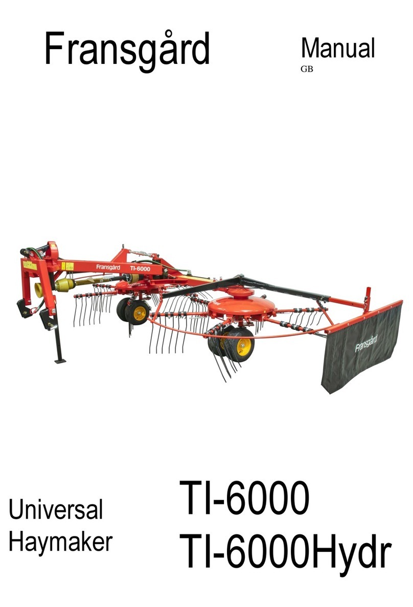
Fransgard TI-5000 User manual

Fransgård
Manual
GB
Universal Haymaker
TI-5000

1
LIST OF CONTENTS Page
Technical Specifications...................................................................................... 1
Safety Regulations............................................................................................... 2
Introduction.......................................................................................................... 2
Mounting.............................................................................................................. 2
Working Position.................................................................................................. 2
Raking up . . . ...................................................................................................... 3
Tedding . . . . . ..................................................................................................... 3
Transport position. . . . ........................................................................................ 3
Ordering Spare Parts........................................................................................... 4
Lubrication and Maintenance .............................................................................. 4
TECHNICAL SPECIFICATIONS
Working width ............................................................3,40m / 11,5' - 4,20m / 14,0'
Transport width....................................................................................2,70m / 8,8'
Working speed,up to........................................................................... 10-15 km/h.
Power requirement ...........................................................................40hp / 30kW.
PTO ................................................................................................. max.400 rpm.
Tyre size ....................................................................................16,5 x 8,00-2 pcs.
Weight..........................................................................................450 kg / 990 lbs.
Number of tines ......................................................................................24 pieces

2
SAFETY PRECAUTIONS
All screens must be correctly positioned and checked before
starting the tedder. It is not advisable to remain in the working
area of the tedder while working parts are rotating.
The machine is made to work in hay and strawcrops, and
must not be used for anything else.
The machine must only be operated by qualified operator.
Machine lubrication, adjustment and setting may only take
place while the tedder is not in use and while the power take-
off is switched off.
Tighten bolts and check settings after approx. 5 hours of use.
Only use original Fransgård spare parts.
Read instructions for use carefully before starting.
INTRODUCTION
The Fransgård Combirake model TI-5000 is one of the
fastest and most effective combirakes on the global market,
and has all the working functions: Tedding, turning over and
raking up.
For tedding, the rake arms are in the locked position, and the
machine leans forward to level the material evenly.
For raking up, the rake arms are cam-track controlled so in
the fact that the tines tilt upwards, allowing the material to
be treated very gently.
When driving with the top bar handle in floating position, the
bolt (42400) has to be removed and the top bar adjusted as
shown in the illustration.
The machine is fitted with balloon tyres with a wide bearing
surface.
The rotor speed and forward speed of the tractor must be
selected on the basis of the type and state of the crop.
PTO: Raking up, 350-max. 400 rpm.
MOUNTING
Mount the connecting frame (55006) on the middle frame
(55528) by means of the adjustment fitting (55005).
Mount the middle frame (55524) on the connecting frame
(55006) using the bolt (55507), and then screw the handle
(51259) and thread spindle onto the fitting on the middle
frame (55524).
Mount the treepoint hitch (55522) on the middle frame
(55524) using the bolt (55523). Mount the fitting (55504),
(55505).
Mount the PTO. fitting (42503).
Mount the wheel fittings (55515). Mount the supporting leg
(55525).
Fit the protection hoop (55512), (55518) and the bracket
(55516), (40274). Mount the PTO shaft.
Mount fitting (55017) with tines.
See also the mounting/spare parts drawings on the following
pages.

3
WORKING POSITION
The Ti-5000 combirake has two work settings for the three-
point suspension:
A: Top bar handle in fixed position.
B: Top bar handle in floating position.
When driving on slopes and hillsides, etc., it is best to have
the three-point suspension in the fixed position (A:).
The TI-5000 combirake has four different working positions
in all.
From the factory the combirake is delivered in pos. 2.
POS.1: RAKING INTO SIDE SWATHS
When raking to the side, the machine always runs at an
angle behind the tractor (adjust bolt 55503). Set the working
width of the machine to the middle position (pos.1) using
handle (55012). The rotors rotate in the same direction
(lever on reversing gear 42447) and are engaged in the
reversing gear in such a way that the pick-up springs
cannot touch, while the rake arms run in the cam guide.
Adjust the cam guide (42440) as shown in the illustration for
pos.1. Adjust the wheels so in the fact that they run parallel
the direction of travel.
The right-hand protective bracket should have been fitted,
while the left-hand protective bracket should be fitted and
adjusted in the central hole on the mounting (55516). Adjust
the catch arm to the required swath using the mounting
(42489).

4
POS.2: RAKING INTO CENTRAL SWATHS
When raking into central swaths, the machine always runs
straight behind the tractor (adjust bolt 55503). Set the
working width of the machine to the middle or widest
position (pos.1 / pos.2) using handle (55012). The rotors
rotate in opposite direction (lever on reversing gear 42447)
and are engaged in the reversing gear in such a way that
the pick-up springs cannot touch, while the rake arms run
in the cam guide. Turn the mounting for the rake arms
(55513) on the-left hand rotor through 180° (see illustration
for pos.2). Remove splint pin (42479) then pull rake arm
mounting back and turn. Then pull the mounting for the rake
arms back and turn, thereby making room to fit the previous
mounting in the cam guide. The mountings should be turned
at the highest level of the cam guide. Turn the rake arms to
the correct working position (see illustration for pos.2). Adjust
the wheels so in the fact that they run parallel to the direction
of travel. The right-hand protective should have been fitted,
while the the outermost hole on the mounting (55516).
Remove the catch arm.

5
TEDDING
For tedding, mount the fitting with the tines in the fixed
position on the rotors. Set the machine by means of the
handle (51259) located at the top of the middle frame so it
leans forward. Do not allow the tines to touch the ground. Set
the working width of the machine to the narrowest
position (pos.3) using handle (55012). The rotors rotate in
opposite direction (lever on reversing gear 42447) and are
engaged in the reversing gear in such a way that the
pick-up springs cannot touch.
TRANSPORT POSITION
Change-over from working position to transport position is as
follows: lift the machine a little off the ground and set it to the
intermediate working width by means of the adjustment fitting
(55012). Release the retaining brackets (55516/40274) and
turn both protection braces behind the machine. Refit the
retaining brackets in the second hole in the protection
braces.
Release the machine from the bolt (55503). The machine
then needs to be turned around until the bolt (55503) can be
mounted as intended on the fitting (55504). Remember to fit
the cotter (1220035). Move fittings with tines to the fittings
which face towards the middle of the machine. Remove the
catch arm
Pos. 3

6
ORDERING SPARE PARTS
The spare part order must contain the following information:
1. Machine type.
2. Spare part number and description-possibly dimensions and number of parts.
LUBRICATION AND MAINTENANCE
Lubricate PTO shaft after every 10 hours of operation, and lubricate the indicated lubrication points as and
when required. Retighten bolts.
The gearbox is filled with 0.8 litres of SAE 90 gear oil. It should be checked daily and topped up if necessary.


Table of contents
Other Fransgard Farm Equipment manuals

Fransgard
Fransgard GT-300AUS User manual

Fransgard
Fransgard BF-7000 User manual

Fransgard
Fransgard SV-250-09SE User manual

Fransgard
Fransgard DM-2450 User manual

Fransgard
Fransgard DM-3250 User manual

Fransgard
Fransgard TI-6000 User manual

Fransgard
Fransgard SV-2500SE User manual

Fransgard
Fransgard SR-3200T User manual

Fransgard
Fransgard Swath Wilter SV-2500 User manual

Fransgard
Fransgard GT-250 DKH User manual