Sperry instrument ADT-222A User manual

(
SUBJECT
GROUND
EQUIPMENT
MANUAL
PN
4030935, 4039390
LIST
OF
CHAPTERS
General
Information
and
Operating Instructions
Description
Operating Instructions
Specifications
Installation
and
Removal
Handling
and
Mounting
Equipment
and
Materials
Installation
Procedures
Installation
Verification
Removal
from
Service
Storage
and
Shipping
Ma
intenance
Introduction
Performance Verification
Theory
of
Operation
Troubleshooting
Adjustment
and
Calibration
Repair
,
,
Special Tools, Fixtures,
and
Test
Equipment
. ,_»r
.,.,.,
.
CHAPTER-SECTION
1-0
1-1
1-2
1-3
2-0
2-1
2-2
2-3
2-4
2-5
2-6
3-0
3-1
3-2
3-3
3-4
3-5
3-6
3-7
To buy, sell, rent or trade-in this product please click on the link below:
http://www.avionteq.com/Honeywell-Sperry-ADT222A-4030935-911-Air-Data-Test-System.aspx
www.avionteq.com

or----------------------------------------------------------

I
----------------
GROUND'
EQUIPMENT
MANUAl,.
PN
4030935,4039390
FOREWORD
The
ADT-222A
Air
Data
Test
System,
Part
No.
4030935-XXX
and
4039390-XXX,
is
the
most
versatile,
accurate, easy
to
use,
air
data
test
instrument currently
available.
When
properly
and
effectively
used
it
can
substantially
reduce
test
and
calibration
times
and
overall costs of maintaining
air
data computers
and
instruments.
The
following
table
is
provided
as
a
definition
of
ADT-222A
configurations:
Nominal
Pneumatic
Voltage
Dash
No.
Calibration Port Required
-XXX
Medium
Location
(V
ac)
-901
Ai
r Front
115
-902
Air
Rear
115
-911
Ai
r Front
230
-912
Air
Rear
230
-SOl
N2
Front
115
-S02
N2
Rear
115
-Sl1
N2
Front
230
-S12
N2
Rear
230
This
manual
has
been
prepared to provide the operator with the information
necessary to operate
and
maintain the
ADT-222A.
A
full
description of the system
is
provided in Chapter 1 along with the system
specifications,
theory of
I operation,
and
manual
operating
instructions.
Chapter 2 contains the information
necessary to
install
the system
and
put
it
"on
line".
Chapter 2 also contains
instructions
for
removing
the
ADT-222A
from
service for storage
and
shipping.
Maintenance information, including
testing,
troubleshooting,
calibration,
and
repair
of the
ADT-222A,
is
contained in Chapter
3.
Acomplete
parts
list
is
provided in Chapter 4.
I
The
4030935-XXX
and
4039390-XXX
ADT-222A's
are identical
test
systems, except
4039390-XXX
contains
an
ASCII
interface
option
that
provides
capability
of
operating the
ADT-222A
automatically
under
control of
any
Automatic Test
Equipment
(ATE).
(Refer
to
Chapter 5.)
the
It
is
recommended
that
the operator read
and
familiarize himself with Chapters 1
and
2 before attempting
to
install
or operate the
ADT-222A.
Foreword
Page
1
Jun
15/S0
+~~!~~V
The
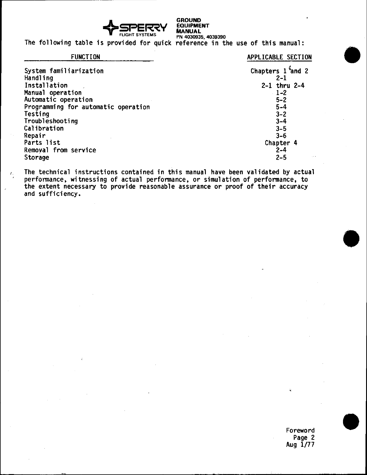
following table
is
provided for quick
FUNCTION
System
familiarization
Handling
Installation
Manual
operation
Automatic
operation
Programming
for automatic operation
Testing
Troubleshooting
Calibration
Repair
Parts
list
Remoyal
from
service
Storage
GROUND
EQUIPMENT
MANUAL
PN4030935,4039390
reference in the
use
of
this
manual:
APPLICABLE
SECTION
Chapters 1'and 2
2-1
2-1
thru
2-4
1-2
5-2
5-4
3-2
3-4
3-5
3-6
Chapter 4
2-4
2-5
/,
The
technical instructions contained in
this
manual
have
been
validated
by
actual
performance, witnessing of actual performance, or simulation of performance, to
the extent necessary
to
provide reasonable assurance
or
proof of
their
accuracy
and
sufficiency.
Foreword
Page
2
Aug
1/77

GROUND
EQUIPMENT
MANUAL
PN
4030935. 4039390
SERVICE
BULLETIN
LIST
In
the
serial
numbering
system assigned to the
ADT-222A,
the
first
three
numbers
of
the
seven-digit
serial
number
on
the
identification
plate
represent the date
of manufacture.
The
remaining
numbers
are a
four-digit
numeric sequence count
of
the item
as
manufactured.
Service
Bulletin
List (Page 1/2)
Feb
1/79

....----------~~~---
--
-----------------
I
Service
Bull
eti
n
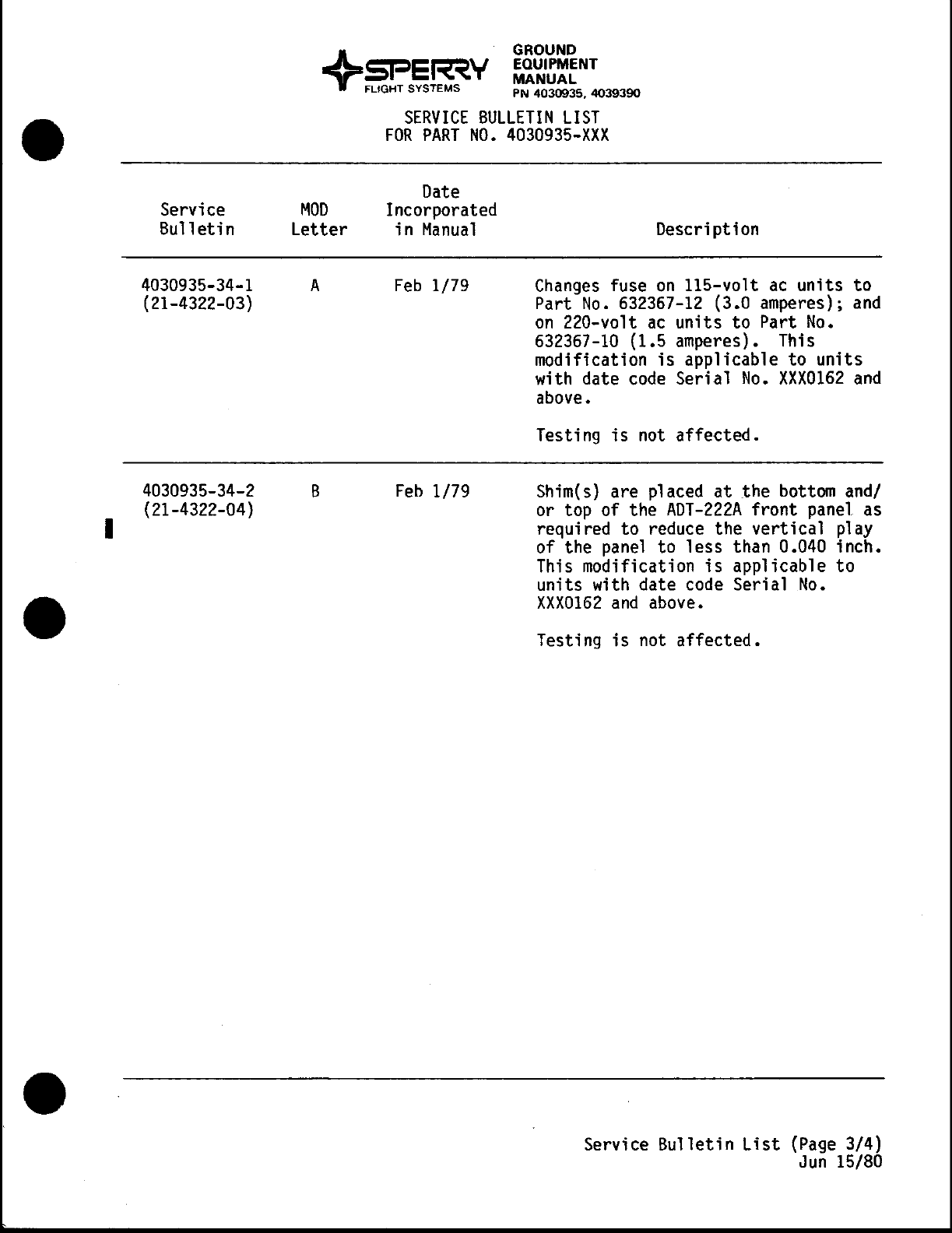
4030935-34-1
(21-4322-03)
4030935-34-2
(21-4322-04)
MOD
Letter
A
B
GROUND
EQUIPMENT
MANUAL
PN
4030935. 4039390
SERVICE
BULLETIN
LIST
FOR
PART
NO.
4030935-XXX
Date
Incorporated
in
Manual
Feb
1/79
Feb
1/79
Description
Changes
fuse
on
lIS-volt
ac
units to
Part
No.
632367-12
(3.0 amperes);
and
on
220-volt
ac
units
to
Part
No.
632367-10
(1.5 amperes). This
modification
is
applicable to
units
with date
code
Serial
No.
XXX0162
and
above.
Testing
is
not
affected.
Shim(s) are placed
at
the
bottom
and/
or top of the
ADT-222A
front panel as
required to reduce the
vertical
play
of the
panel
to
less
than 0.040 inch.
This modification
is
applicable
to
units with date
code
Serial
No.
XXX0162
and
above.
Testing
is
not
affected.
Service
Bulletin
List
(Page
3/4)
Jun
15/80

GROUND
EQUIPMENT
MANUAL
PN
4030935, 4039390
CHAPTER
1
GENERAL
INFORMATION
AND
OPERATING
INSTRUCTIONS
1-0
Aug
1/77

Chapter-
Section
1-1
1-2
1-3
GROUND
EQUIPMENT
MANUAL
PN
4030935,
4039390
CHAPTER
1
GENERAL
INFORMATION
AND
OPERATING
INSTRUCTIONS
Table of Contents
DESCRIPTION
1.
General
Description
2. Physical Description
3. Functional Description
OPERATING
INSTRUCTIONS
1.
General
2.
System
Initialization
3.
Measure
Mode
Operation
4. Control
Mode
Operation
5.
Leak
Test Operation
6.
Dynamic
Operation
7. Failure Procedures
8. Error
Messages
SPECIFICATIONS
1.
Leading
Particulars
2. Connections
and
Fittings
3.
Range
of Operation
4. Protection Limits
5.
Performance
Specifications
Page
1
2
5
1
5
8
9
11
13
14
15
1
2
2
4
4
1-0
Contents
Aug
1/77

I
Section
1.
1.
General
Description
GROUND
EQUIPMENT
MANUAL
PN
4030935. 4039390
Description
The
ADT-222A
Air
Data
Test
System
(figure 1-1)
is
a precise,
stable,
easy to
use
pressure control
system
designed to precisely simulate
and
accurately
measure
the
pneumatic
pressures associated with
an
aircraft
in
flight.
Its
operational
and
design features
were
selected to
meet
the needs of those
who
use,
repair,
or
manufacture precision
pneumatic
avionic equipment.
Conse-
quently,
it
is
ideally suited for laboratory, shop, or production use.
In
addition to
its
manual
operation
capability,
the
ADT-222A
is
available with
an
optional automatic
test
equipment
(ATE)
interface
which
allows
remote
slave operation of the
ADT-222A
by
an
ATE.
When
equipped with
this
option,
the
ADT-222A
is
fully
programmable
and
capable of being controlled
by
an
ATE
system
or
any
programmable
terminal
employing
an
IEEE
Standard
488-1975
interface.
Pressure
measurement
and
control
is
provided in terms of inches of
mercury
or
millibars;
altitude
in
feet
or meters;
and
airspeed in knots or kilometers/
hour, as selected
by
the operator. Aspecial purpose
digital
processor
operates in conjunction with
two
precision vibrating
diaphragm
digital
pressure sensors
and
electrically
controlled pressure regulation valves to
provide high speed control
and
measurement
response with readout displays
converted to the units desired
by
the operator.
I~
ADT-222A
Air
Data
Test
System
Figure
1-1
XX2
SERIES
HAVE
PNEUMATIC
CONNECTORS
ON
REAR PANEL
32315
A1
1-1
Page
1
Feb
1/79
+ GROUND
~E~\.J
EOUIPMENT
~I-
I~
....T
MANUAL
FLIGHT
SYSTEMS
PN
4030935.
4039390
When
used as a
transfer
standard, the
ADT-222A
accurately measures the
pressures applied to
its
input ports with
sufficient
resolution
and
stability
to
resolve a
I-foot
change in
altitude
at
60,000
feet.
Because of
its
extremely high
calibration
stability,
it
can
be
used to
calibrate
other
laboratory pressure standards
and
air
data
test
instruments as well as
air
data avionic equipment.
When
used as a pressure
controller,
the desired pressure
or
altitude
and
airspeed values are entered via
digital
lever
switches
on
the
front
panel.
Pressure
transition
rates
are selected
by
digital
thumbwheel
switches
on
the
front
panel
and
are precisely
controlled
to provide extremely
smooth
pressure
transitions
with
no
overshoot. A
single
pushbutton switch
initiates
control
to
the
newly
selected
values.
The
system will also respond to
dynamic
signals applied to a
dynamic
input
connector
on
the
rear
panel.
As
an
example, a function generator
can
be
used
to
superimpose sinusoidal pressure
waves
on
eitherP
s
or
Pt.
The
ADT-222A
employs
built-in-test
(BIT)
programming
and
hardware to monitor
its
own
operation,
detect
system
failures
and
improper
commands
from
the
operator,
and
shut
down
the system
when
a
fault
is
detected. This
BIT
capability
provides
fail-safe
operation
by
protecting the
unit
under
test
(UUT)
against possible hazards during
test.
Protection
is
provided against
UUT
damage
caused
by
either
operator
error
or
ADT-222A
failure.
The
operator
has
the option of
selecting
subsonic or supersonic protection
limits
to
match
the
capabilities
and
requirements of the
UUT.
In
addition to
electrical
power,
operation of the
ADT-222A
requires
an
exter-
nal
.pressure source
and
two
external
vacuum
sources.
The
exact requirements
for
all
of the inputs are
listed
in
Chapter
I,
section 3.
The
ADT-222A
is
calibrated
at
the factory for
use
with
either
dry
air
(-901, -902, -911,
-912)
or
dry nitrogen (-801, -802, -811, -812) as the pressure source.
The
calibration
medium
is
designated
by
a
front
panel decal.
2. Physical Description
The
ADT-222A
consists
of a
power
supply,
digital
control cards,
two
pressure
sensors,
and
two
pneumatic control systems
mounted
on
a
chassis.
The
front
panel contains operating controls
and
displays,
and
the
rear
panel contains
pressure
fittings
and
connectors for external control
and
test
equipment.
It
is
packaged in
an
aluminum
alloy enclosure designed for
either
rack
mounting
or
bench
top use. Dimensions, weight,
and
other leading
particulars
are
listed
in Chapter
I,
section
3.
All
primary operating controls
and
displays are located
on
the
front
panel,
shown
in figure 1-2. Pneumatic
fittings
for connection to the
UUT
are
located
on
the
front
panel for
units
with dash
number
XXI,
and
for
units
with
dash
number
XX2,
the
fittings
are
on
the
rear
panel.
The
vertical
row
of
five
lighted
pushbutton switches
at
the top
center
of the
front
panel
visually
divides the
static
pressure panel functions
from
the
pitot
(total)
pressure panel functions.
Four
of the pushbutton switches
are
used to
select
the display
mode
(the parameter
and
units to
be
displayed).
The
fifth
1-1
Page
2
Aug
1/77
I
I
GROUND
EQUIPMENT
MANUAL
PN
4030935. 4039390
]lj
IjIj·lj
Ij·I91II[
0
tIIE,.c COIiIfdND ENTER
-I\l-
wtOLiT
-f\
\.-
~'::.~
J(c[C[~~
~
[D
D
)[C{C(C!
(~~f:~!..c
MT(
~
PRfCISIOfI
1tAT[
un
Co.MJC)
DISA8U
....
DYtrtMIIC
DlSoIoIU
SUBSONIC
ATE
CONtAOL.ASUIlf:
1llEASUM:
~R
IW'UT
~
LIMIT LIMIT
cpDDDDDDDDc::t}
'\
St&ITQI',
"'r
"'r
SttUTOfF
co."...
~
StAne
_
Oft
PlTOT
PIIIfSaIJIE
JUII
PAES!UU
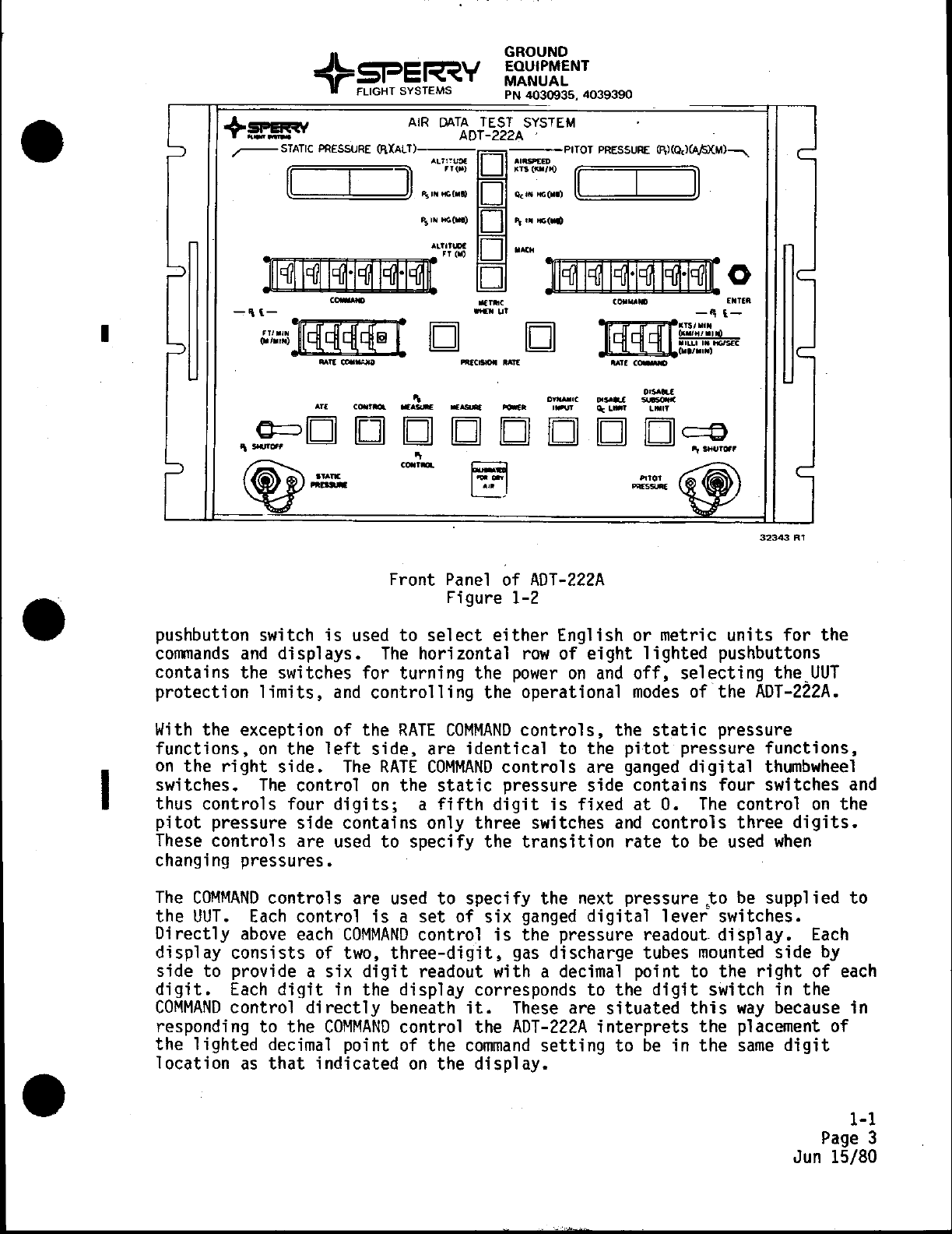
Front
Panel
of
ADT-222A
Figure 1-2
32343
R1
pushbutton switch
is
used
to
select
either
English or metric
units
for
the
commands
and
displays.
The
horizontal
row
of eight lighted pushbuttons
contains the switches for turning the
power
on
and
off,
selecting
the
UUT
protection
limits,
and
controlling
the operational
modes
of the
ADT-222A.
With
the exception of the
RATE
COMMAND
controls,
the
static
pressure
functions,
on
the
left
side,
are identical to the
pitot
pressure functions,
on
the
right
side.
The
RATE
COMMAND
controls
are
ganged
digital
thumbwheel
switches.
The
control
on
the
static
pressure side contains four switches
and
thus controls four
digits;
a
fifth
digit
is
fixed
at
O.
The
control
on
the
pitot
pressure side contains only three switches
and
controls
three
digits.
These
controls
are
used
to specify the
transition
rate
to
be
used
when
changing pressures.
The
COMMAND
controls are
used
to
specify the next pressure
~o
be
supplied
to
the
UUT.
Each
control
is
a
set
of
six
ganged
digital
lever
switches.
Di
rectly
above
each
COMMAND
control
is
the pressure readout
di
spl ay.
Each
display
consists
of two,
three-digit.
gas
discharge tubes
mounted
side
by
side to provide a
six
digit
readout with a decimal point to the
right
of
each
digit.
Each
digit
in the display corresponds to the
digit
switch in the
COMMAND
control
directly
beneath
it.
These
are
situated
this
way
because in
responding to the
COMMAND
control the
ADT-222A
interprets
the placement of
the lighted decimal point of the
command
setting
to
be
in
the
same
digit
location
as
that
indicated
on
the
display.
1-1
Page
3
Jun
15/80
+ GROUND
~E~V
EQUIPMENT
.;;:;11- ..
~
~
T
MANUAL
FLIGHT SYSTEMS PN
4030935.
4039390
The
PRECISION
RATE
control for
each
side
is
a lighted pushbutton switch
located next to the
RATE
COMMAND
control
and
is
used
to
select
extra-precise
control of the pressure
transitions.
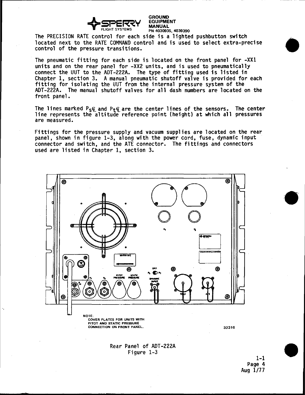
The
pneumatic
fitting
for
each
side
is
located
on
the front
panel
for
-XX1
units
and
on
the rear panel for
-XX2
units,
and
is
used
to pneumatically
connect the
UUT
to the
ADT-222A.
The
type of
fitting
used
is
listed
in
Chapter 1, section 3. A
manual
pneumatic
shutoff valve
is
provided for
each
fitting
for
isolating
the
UUT
from
the internal pressure
system
of the
ADT-222A.
The
manual
shutoff valves for
all
dash
numbers
are located
on
the
front panel.
The
lines
marked
Ps~and
Pt~are
the center
lines
of the sensors.
The
center
line
represents the
altitude
reference point (height)
at
which
all
pressures
are measured.
Fittings
for the pressure supply
and
vacuum
supplies are located
on
the rear
panel,
shown
in
figure 1-3, along with the
power
cord, fuse,
dynamic
input
connector
and
switch,
and
the
ATE
connector.
The
fittings
and
connectors
used
are
listed
in Chapter 1, section
3.
00
o 0
NOTE;
COVER PLATES FOR UNITS WITH
PITOT
AND
STATIC
PRESSURE
CONNECTION
ON
FRONT
PANEL.
.., ®
...
Cl..
...-
.....
Rear
Panel
of
ADT-222A
Figure
1-3
LJ
D ®
®
32316
1-1
Page
4
Aug
1/77

I
GROUND
EQUIPMENT
MANUAL
PN
4030935,4039390
Also
located
on
the
rear
panel
are
two
internal pressure regulator
controls.
The
pressure regulator controls are factory
set
and
should not
be
adjusted.
The
circuit
cards
and
major subassemblies are plug-in interchangeable for
quick
and
easy maintenance.
3.
Functional Description
The
pneumatic
system
of the
ADT-222A,
shown
in figure
1-4,
consists of
two
pneumatic paths, each containing a pneumatic control section
and
a measure-
ment
section.
The
sections are
isolated
from
each
other
and
from
the
UUT
connection
fittings
(P
s
andPt
ports)
by
solenoid operated valves. Extra
UUT
pneumatic
isolation
is
provided
by
manual
valves.
The
measurement
section of
either
path consists of a solenoid valve
at
each
end
of the section, a
30
cubic inch
volume
tank,
and
a pressure sensor.
The
pneumatic control section of
either
path consists of a pressure regulator for
the
inlet
supply pressure, pneumatic
line
and
fitting
for the
vacuum
supply,
and
a pneumatic servo control valve.
Both
paths join
at
the pressure supply
line
and
use
a
common
pneumatic
filter
and
solenoid valve
for
isolation
from
the pressure supply. .
There are
two
basic
modes
of operation: the
measure
mode
and
the control
mode.
In
the measure
mode
all
pressure
and
vacuum
supply
lines
are shut
off
and
the
pneumatic control section
is
shut
off
from
the
measurement
section.
The
measurement
section,
however,
is
open
to
the
test
ports.
Therefore, in the
measure
mode,
valves
Kl
and
K3
are
open
while valves
K2,
K4,
K5,
and
KG
are
closed.
In
the control
mode,
all
of the valves are
open
and
the pressures in both
paths are controlled
by
the respective pneumatic servo control valves,
CVl
and
CV2.
Operation of the
ADT-222A
is
controlled
by
a
system
control section
which
receives
instructions
from
the operator via the front
panel
controls or
from
an
ATE
via the optional
ATE
interface.
It
receives
measurement
data
from
the
sensors, performs the necessary calculations
and
conversions,
and
sends the
pressure values
to
the front
panel
for display.
In
the control
mode,
it
also
compares
the
measured
values
to
the input
commands
and
controls the pressure
control valves to obtain the desired response.
The
system control section also performs
all
BIT
functions
and
causes the
ADT-222A
to
either
shut
down
to
protect the
UUT,
or
just
ignore the input
commands,
whenever
an
equipment
failure
or
an
operator
error
is
detected.
A
more
detailed description of the operation of the
ADT-222A
is
contained in
Chapter
I,
section 2.
1-1
Page
5
Jun
15/80

I
I
GROUND
EQUIPMENT
MANUAL
PN
4030935,4039390
~DT-2ZzA------------------------------'
I X :
.----G)01~-~'Hl6ii'p_r<l
:
.,yac_
......
I
I
I~-«)()>--.L.,
~'!s
-,
.1
I
X :
I
I
I
I
I
»--i,~"
"""
I
I
I
..
I
........
I
I
. I
~--------------------------~---------
PNEUMATIC
DIAGRAM
o
AO..I
REGoULATOQ
@]
PNEUMATIC.
IIOLUME
(~
...
)
® SOLENOID
VALVE
0
~~¥~t':'~~~F
®
MANUAL
So.uTOo:!' @ PNEUMATIC.
O:ILTER
VALVE
Pneumatic
Diagram
Figure 1-4
E4030935-100-S(R2)
1-1
Page
6
Jun 15/80
1.
General
GROUND
EQUIPMENT
MANUAL
PN
4030935,4039390
Section 2. Operating Instructions
--~
This section contains
manual
operating procedures only. Refer to Chapter 5,
section 2 for procedures for automatic operation.
NOTE:
Before operating the
ADT-222A,
the user should
familiarize himself with subsections 7
and
8
of
this
section.
Before operating the
ADT-222A
it
is
helpful for the operator to understand
the general relationships
between
altitude,
airspeed,
and
pressure.
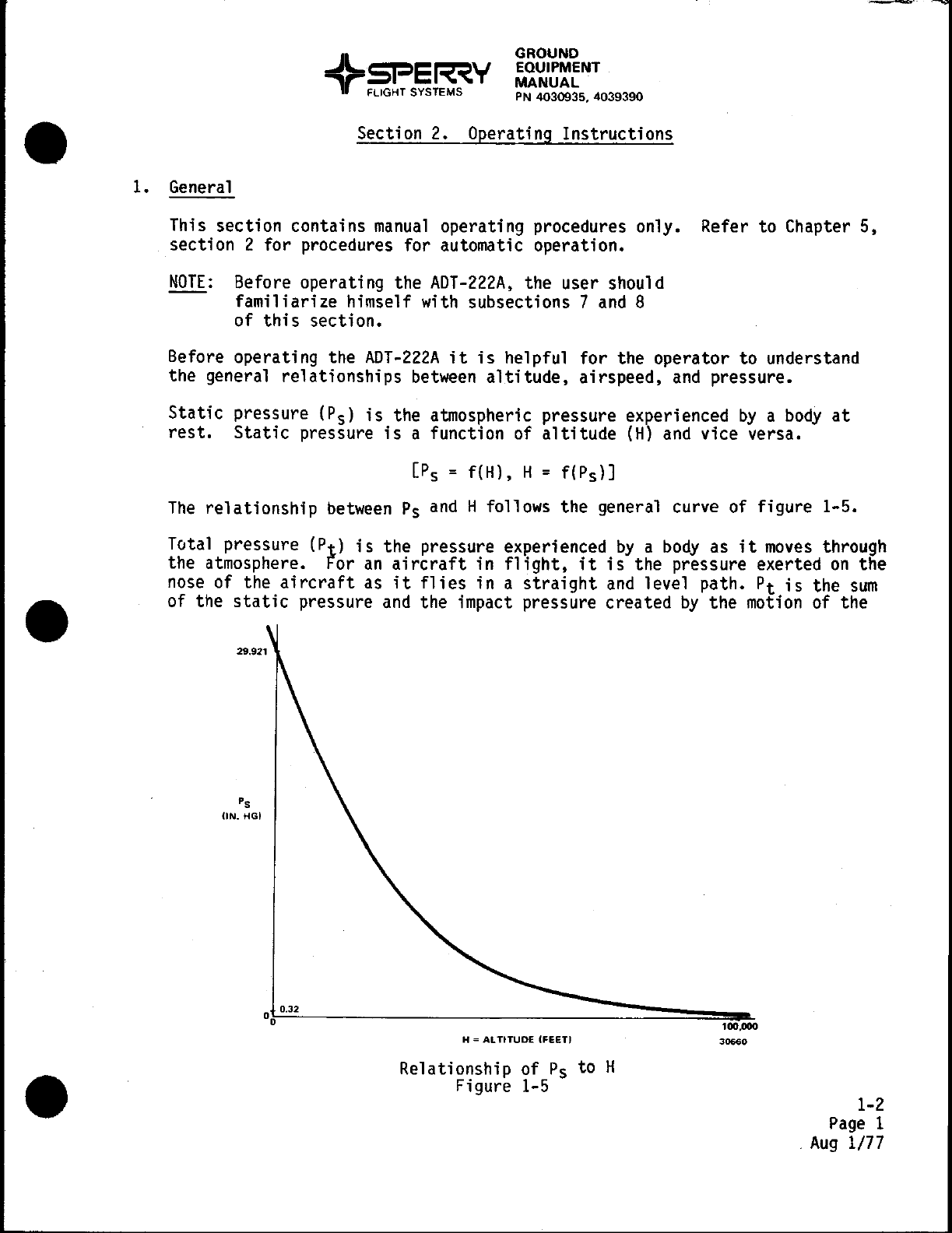
Static
pressure
(P
s)
is
the atmospheric pressure experienced
by
a
body
at
rest.
Static
pressure
is
a function
of
altitude
(H)
and
vice versa.
[P
s =f(H), H=
f(P
s)]
The
relationship
between
Ps
and
H follows the general curve of figure 1-5.
Total pressure
(P
t)
is
the pressure experienced
by
a
body
as
it
moves
through
the atmosphere.
For
an
aircraft
in
flight,
it
is
the pressure exerted
on
the
nose
of the
aircraft
as
it
flies
in a
straight
and
level path. Pt
is
the
sum
of the
static
pressure
and
the impact pressure created
by
the
motion
of the
'.
(IN.
HGI
10
-.3-2-
___
-==:::::::::::~~
o~ 100.000
H = ALTtTUDE (FEETI
Relationship of
Ps
to H
Figure 1-5
30660
1-2
Page
1
.
Aug
1/77
I
+ GROUND
sr=E~V
~':1~~~NT
FLIGHT
SYSTEMS
PN
4030935.
4039390
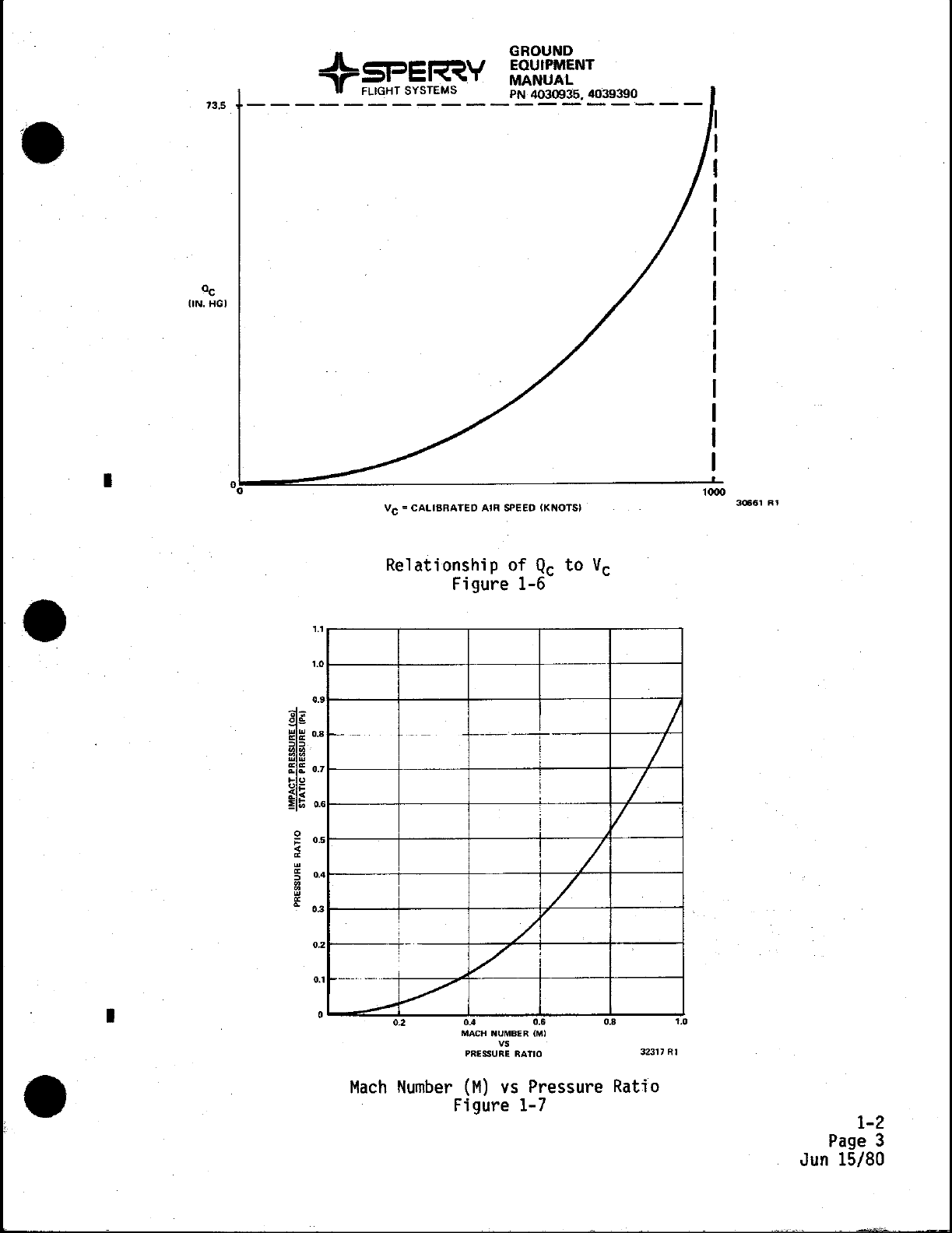
air.
Airspeed
(Vcl
is
a function of
the
impact pressure
(Qcl
and,
therefore,
a function of
the
relation
of
Pt
to
Ps-
Q
c = f(Vcl,
Vc
= f(Qcl
Pt = Ps +
Qc
Vc
=
f(Pt
-Psl
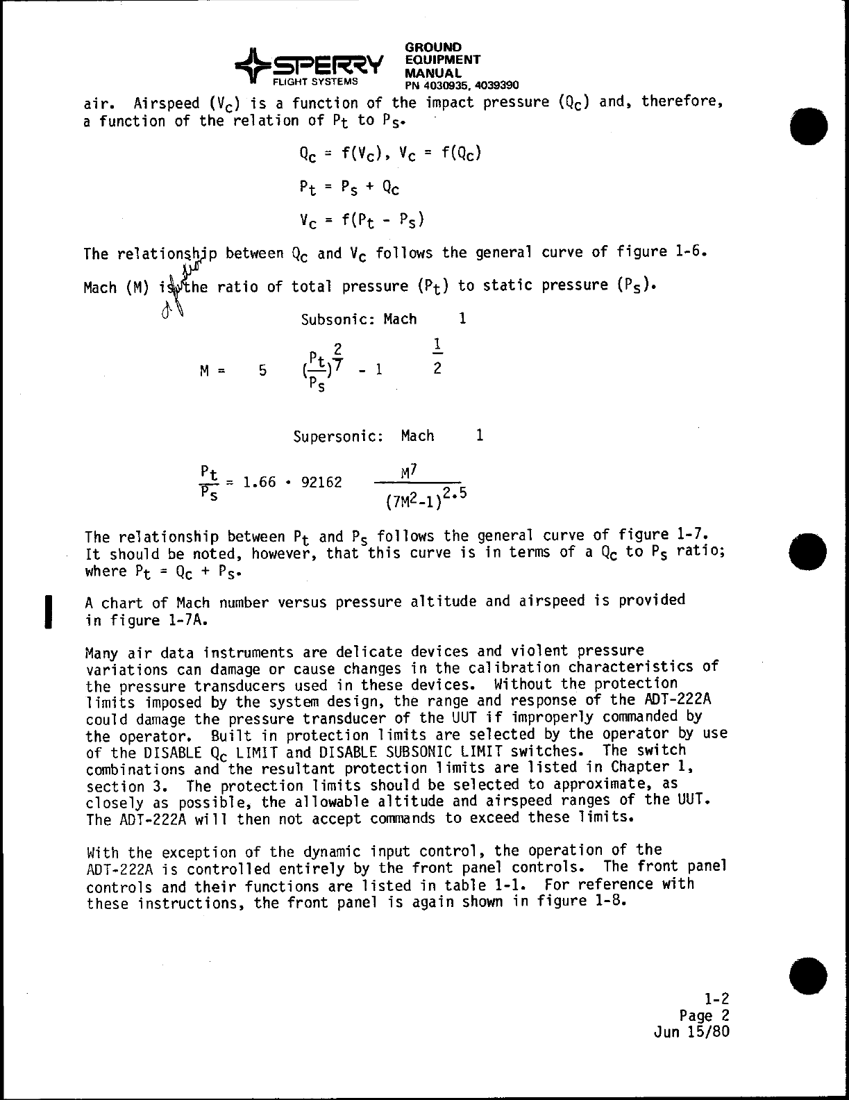
The
relati~n~p
between
Q
c
and
Vc
follows
the
general curve of
figure
1-6.
Mach
(Ml
~~the
ratio
of
total
pressure
(Ptl
to
static
pressure
(Psl.
Subsonic:
Mach
1
M = 5
1
2
Supersonic:
Mach
1
Pt -1.66 •
92162
p;-
The
relationship
between
Pt
and
Ps follows
the
general curve
of
figure
1-7.
It
should
be
noted, however,
that
this
curve
is
in terms of a
Qc
to
Ps
ratio;
where
Pt
=
Qc
+ Ps•
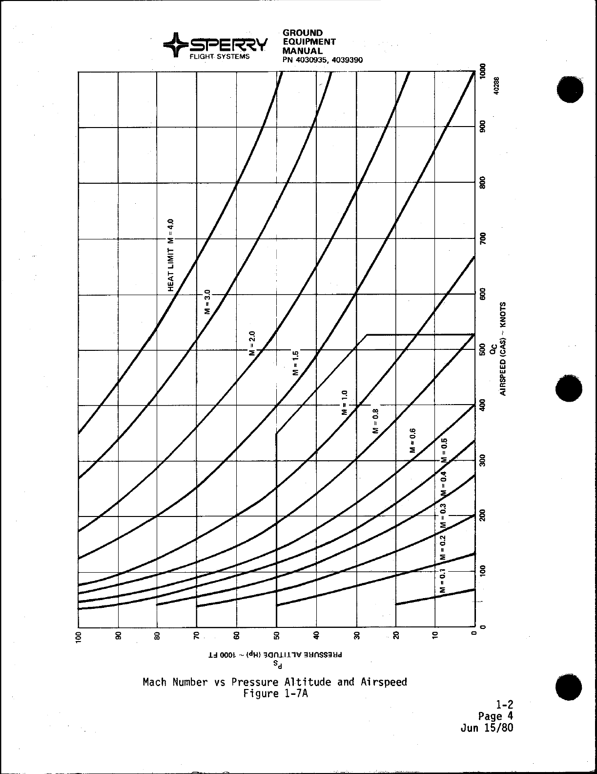
A
chart
of
Mach
number
versus pressure
altitude
and
airspeed
is
provided
in
figure
1-7A.
Many
air
data instruments are
delicate
devices
and
violent
pressure
variations
can
damage
or cause changes in the
calibration
characteristics
of
the
pressure transducers used in
these
devices. Without
the
protection
limits
imposed
by
the system design, the range
and
response of
the
ADT-222A
could
damage
the
pressure transducer of
the
UUT
if
improperly
commanded
by
the
operator. Built in protection
limits
are
selected
by
the operator
by
use
of
the
DISABLE
Q
c
LIMIT
and
DISABLE
SUBSONIC
LIMIT
switches.
The
switch
combinations
and
the
resultant
protection
limits
are
listed
in
Chapter
I,
section
3.
The
protection
limits
should
be
selected
to
approximate, as
closely
as possible, the allowable
altitude
and
airspeed ranges of
the
UUT.
The
ADT-222A
will then not accept
commands
to
exceed
these
limits.
With
the exception of the
dynamic
input
control,
the
operation of
the
ADT-222A
is
controlled
entirely
by
the
front
panel
controls.
The
front
panel
controls
and
their
functions are
listed
in
table
1-1.
For
reference with
these
instructions,
the
front
panel
is
again
shown
in
figure
1-8.
1-2
Page
2
Jun 15/80
73.5
"c
UN.HGJ
•
•
GROUND
EQUIPMENT
MANUAL
PN4030935.4039390
-------------------
OO~--~~~~::=------------------~l~~~
,.
,
'.0
o.
•
-
.•..
7
•
o
-
o.
~
5
•
< 0,
~
4
f 0.3
0,
2
Vc
= CALIBRATED AIR
SPEED
(KNOTS)
Relationship of Q
c
to
Vc
Figure
1-6
._-
I
_.
----
j
!
!
! /I
I
1/
, A
.-+-
,/'
I
/
/
/
/
1
----"
_.
j...-/'
0,
o 0.2
0.4
0.'
0.8
'.0
MACH NUMBER (M)
V,
PRESSURE
RATIO
32317
R1
Mach
Number
(M)
vs
Pressure Ratio
Figure 1-7
30661
Rl
1-2
Page
3
Jun
15/80
GROUND
EQUIPMENT
MANUAL
PN
4030935, 4039390 8
c
~
.,
.,
N
0
..
c
5l
~----~--~----~----~~---J,f--~----~f----+--~-t-----1~
c c c
S!
'" '"
Mach
--~~~--~--~--~-----b~~--+----J~------~------i~
~
2
"
-
---iI/-------;.4-------f-i!---+--~y
c 0
~
~O~
c c c c
:i!
....
'"
on
..
.L~
OOOL
-(dH)
30n.Ll.L
lit
311nSS311d
Sd
Number
vs
Pressure Altitude
and
Figure
1-7A
o
w
i
;;:
--+-+---b----II~
c
S!
N
Ai
rspeed
-----I
~
c
c
1-2
Page
4
Jun
15/80
"
Table of contents
Other Sperry instrument Test Equipment manuals


Popular Test Equipment manuals by other brands

intrepid
intrepid neoECU AVB/TSN user guide

Baker Hughes
Baker Hughes Druck DPI 620 Genii Safety Instructions and User Guide

Agilent Technologies
Agilent Technologies Agilent 34980A Application note

Jula
Jula Meec Tools 405-056 User instructions

Cascade Microtech
Cascade Microtech IZI Probe Quick reference guide

UEi
UEi C161 quick start guide

Ripley
Ripley ODM TTK 210 User's manual and troubleshooting guide

Western Digital
Western Digital WD Quick Tester Quick reference guide

Tektronix
Tektronix PM 101 instruction manual

Andatech
Andatech AlcoSense SOBERPOINT 3 user manual

Valhalla Scientific
Valhalla Scientific 2701C CALIBRATION PROCEDURE

Dixon
Dixon Bayco FT450 instructions


